Week 2 - Flow over a Cylinder.
AIM:
Simulate the flow over a cylinder and explain the phenomenon of Karman vortex street.
Theory:
The flow around bluff bodies is an area of great research of scientists for several years. bluff body can be defined as a body that, as a result of its shape, has separated flow over a substantial part of its surface. Usually bluff bodies induce flow separation at positions where the velocity at the edge of the boundary layer is higher than the free stream velocity. here the bluff body we taken is cylinder. Vortex shedding is one of the most challenging phenomenon in laminar flows. due to flow over cylinder we can clearly visualize the vortex sheddings when the reynolds number is greater than 40.
karmar vortex street:
it is a repeating pattern of swirling vortices, caused by a process known as vortex shedding, which is responsible for the unsteady separation of flow of fluid around the bluff bodies. mostly vortex sheddings have more disadvantages. when wind with high speed passes the long pole, the vortex sheddingd occur there and then the pole start oscillating. due to oscillations the vibration gets generated in the pole which creates the damage to the pole. there is a dimensional number called Strouhal number is associated with oscillations of flow. This phenomenon was first studied by Strouhal. the below is the formula to calculate the strouhal number
strouhal number(St) = `(f*D)/U`
where f is the frequency of oscillations
D is the charecterstic length of bluff body, here bluff body we taken is cylinder and its charecterstic length is diameter of cylinder.
U is the free stream velocity of fluid pass the cylinder.
below figure represents how th vortex sheddings developed during the flow over cylinder.
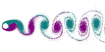
the simulation of flow over cylinder is done using ansys fluent software. we have to follow the below steps to simulate the flow
1.Geometry:
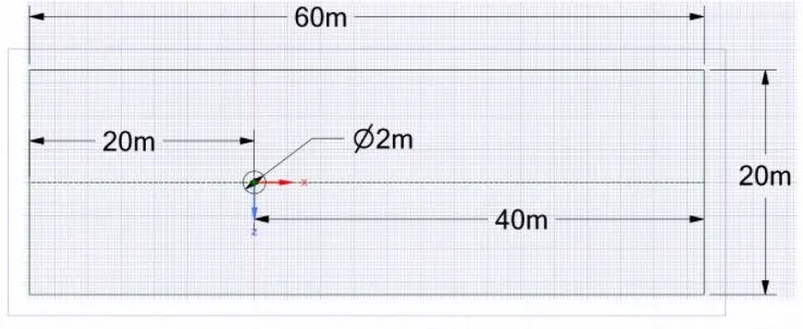
the aboce figutr represents dimensions for the flow over the cylinder in a domain. now after deleting the inside circle for simulation we are going tto get the below figure.
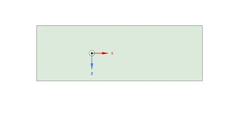
first we have to create the above two dimensional geometry. the diameter of the cylinder we have taken is 2m with minimum thickness, the rest portion is flow field through which fluid pass the cylinder.
2.Mesh:
we have to create the mesh for the above geomtry. the element size i have taken here is 0.25m with triangular cells.
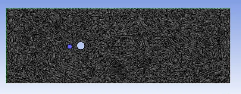
there are 40502 triangular cells have been created in the geometry.
3.Setup:
we have to create the setup by taking the inlet velocity of fluid is 1 m/s. the fluid we have taken with our own speciefied density and viscosity.
density of fluid is 1 kg/m^3
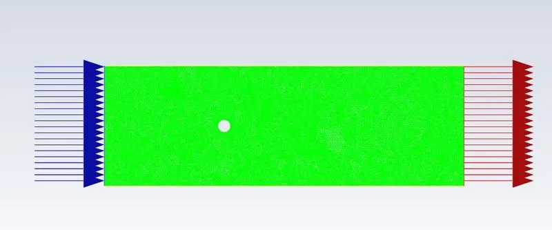
viscosity we have taken based upon the calculations needed to solve the given problems. we are taking the flow to be laminar. blow arrows represent the inlet and red arrows represent the outlet flow and the boundary over cylinder is named as wall and the top and bottem of domain is named as symmetry.
the below are the two parts we are going to calculate
PART-I
- Simulate the flow with the steady and unsteady case and calculate the Strouhal Number for Re= 100.
PART-II
- Calculate the coefficient of drag and lift over a cylinder by setting the Reynolds number to 10,100,1000,10000 & 100000. (Run with steady solver)
- Discuss the effect of Reynolds number on the coefficient of drag.
PART-1:
unsteady case-
here i have used coupled scheme for pressure-velocity coupling with standard method initialization and i have taken time step size as 0.1 seconds to reduce the errors. the viscosity of the fluid is 0.02 kg/m.s , so the reynolds number of flow will be
reynold number(Re) = `(V*D)/mu`
= 1*2/0.02 = 100
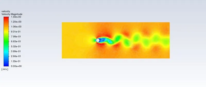
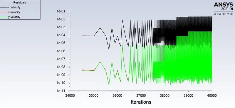
after running the problem the solution gets converged after 28000 iterations. the below are the plots obtained after converging of solutions
velocity countour plot:
moniter point velocity plot:
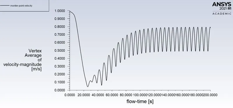
moniter point is the point located at some distance from the centre of the cylinder, this point is located at the right side of the cylinder. the vortex sheddings are formed to the right side of the cylinder. it means the velocity goes on changing at the right side of cylinder. to know how the velocity is varying here we have taken moniter point and we can see how the velocity getting chnages.
residuals plot:
coefficent of drag plot:
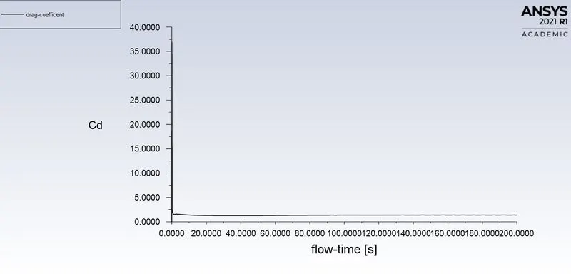
the converged coefficent of drag at the wall due to flow over cylinder is 1.3709916
coefficent of lift plot:
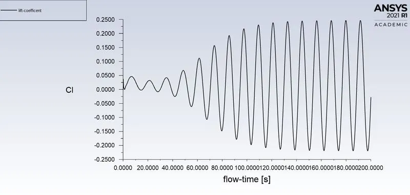
the converged coefficent of drag at the wall due to flow over cylinder is -0.027627
to find the strouhal number, first we have to calculate the frequency of vortex sheddings. to calculate the frequency of vortex sheddings we have to use coefficent of lift plot , we have to take the conveged cycles from the plot.
frequency of vortex sheddings = total number of cycles/ time taken for the cycles to complete
= 2/(162-139)
= 0.08695
strouhal number = (0.08695*2)/1 = 0.1739
steady case-
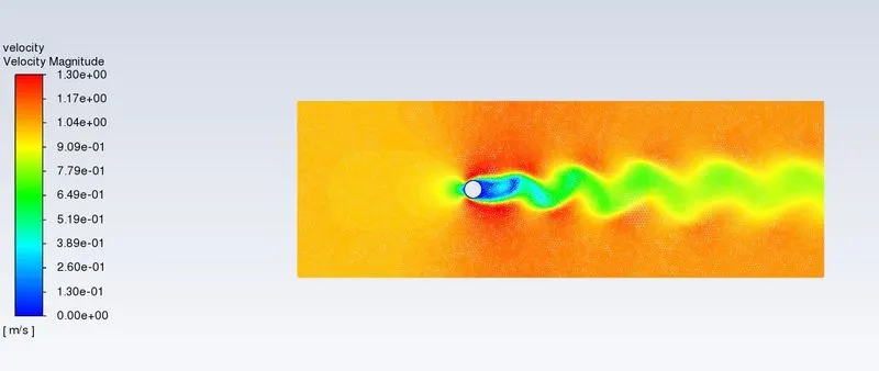
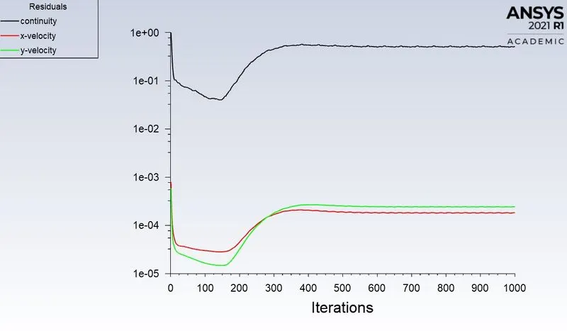
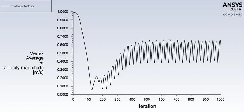
here i have used simple scheme for pressure-velocity coupling with hybrid method initialization. the viscosity of the fluid is 0.02 kg/m.s , so the reynolds number of flow will be 100.the below are the plots obtained after converging of solution
velocity contour plot:
residuals plot:
moniter point velocity plot:
coefficent of drag plot:
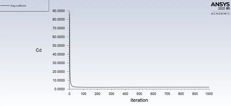
the converged coefficent of drag at wall due to flow over cylinder is 2.187592
coefficent of lift plot:
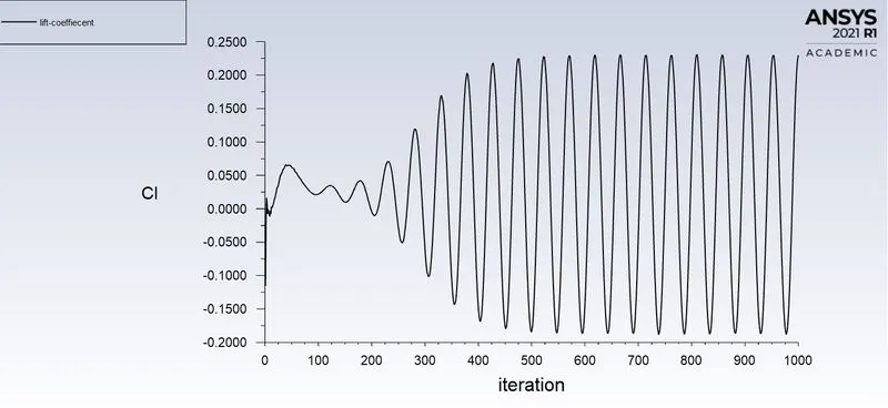
the converged coefficent of lift at the wall due to flow over cylinder is 0.22981894
PART -II:(steady state condition)
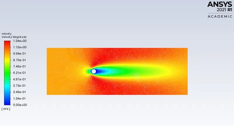
i. when reynolds number is equal to 10
velocity contour plot:
coefficent of drag plot:
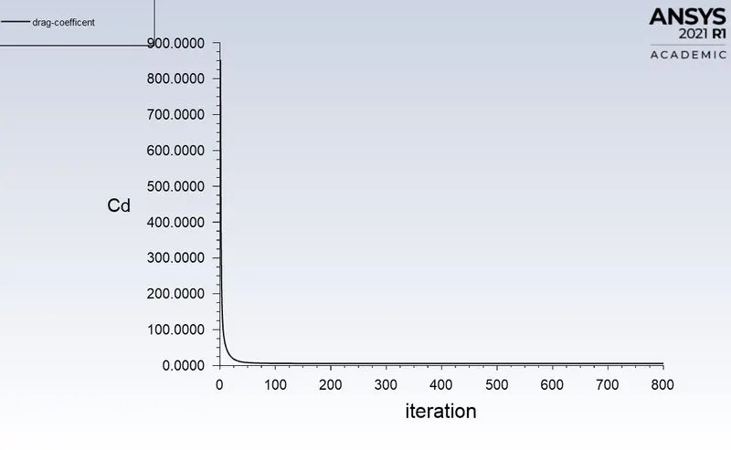
converged coefficent of drag at wall due to flow over cylinder is 5.4277701
coefficent of lift plot:
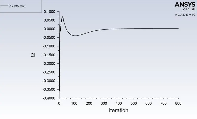
converged coefficent of lift at wall due to flow over cylinder is 0.0014836694
ii. when reynolds number is equal to 100
velocity contour plot:
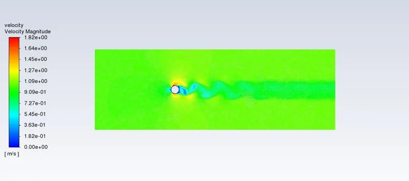
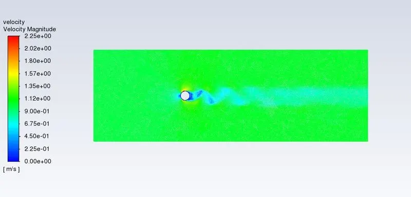
when reynolds number greater than 40, the vortex sheddings gets developed during the flow. due to vortex sheddings the osciallations gets generated at the right side of cylinder.
coefficent of drag plot:
the converged coefficent of drag at wall due to flow over cylinder is 2.187592
coefficent of lift plot:
the converged coefficent of lift at the wall due to flow over cylinder is 0.22981894
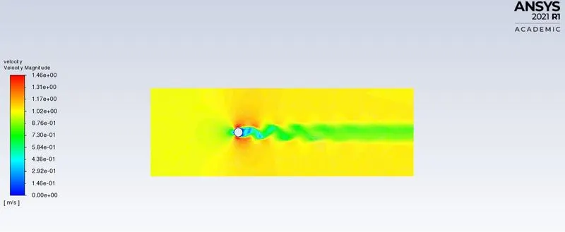
iii. when reynolds number is equal to 1000
velocity contour plot:
coefficent of drag plot:
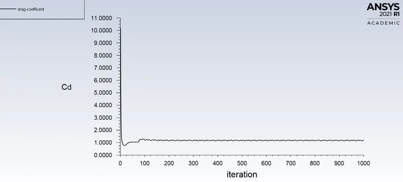
the converged coefficent of drag at the wall due to flow over cylinder is 1.1781382
coefficent of lift plot:
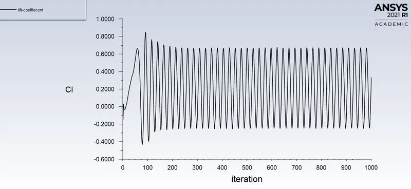
the converged coefficent of lift at the wall due to flow over cylinder is 0.33335345
iv. when the reynolds number is equal to 10000
velocity contour plot:
coefficent of drag plot:
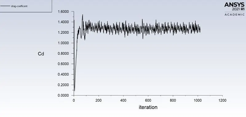
the converged coefficent of drag at the wall due to flow over cylinder is 1.2001873
coefficent of lift plot:
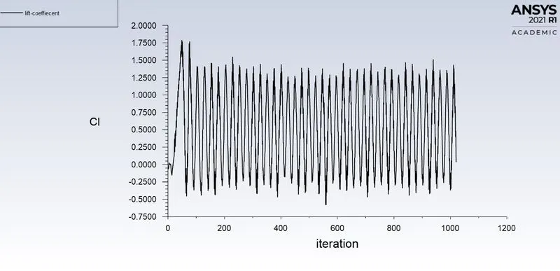
the converged coefficent of lift at the wall due to flow over cylinder is 0.034589354
v. when reynolds number is equal to 100000
velocity contour plot:
coefficent of drag plot:
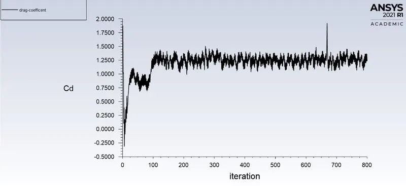
the converged coefficent of drag at the wall due to flow over cylinder is 1.2359461
coefficent of lift plot:
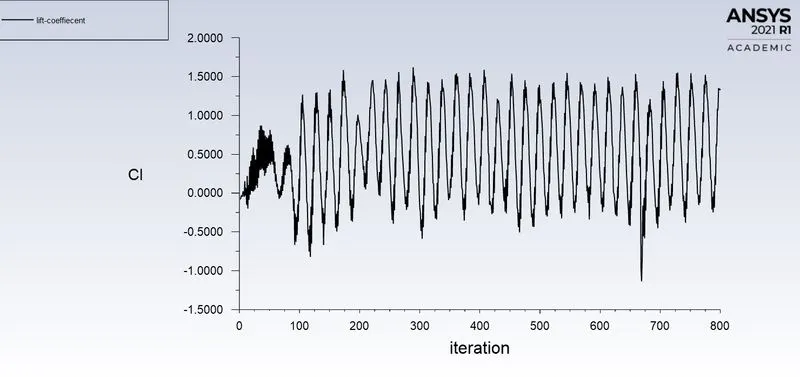
the converged coefficent of lift at the wall due to flow over cylinder is 1.3267087
Table:
| Reynold number | coefficent of drag | coefficent of lift |
| 10 | 5.42777 | 0.00148 |
| 100 | 2.187592 | 0.2298 |
| 1000 | 1.178138 | 0.3333 |
| 10000 | 1.20018 | 0.034589 |
| 100000 | 1.2359 | 1.3267 |
conclusion:
1.by increasing the reynold number, the coefficent of drag decreases and coefficent of lift getting increased upto reynold number 1000.
2. with increasing of reynolds number greater than 1000, the coefficent of drag and lift are taking more iterations compared to reynold number less than or equal to 1000.
Referred research paper:
https://www.sciencedirect.com/science/article/pii/S0307904X08000243