Week 2 - Flow over a Cylinder.
Aim: To Simulate the flow over a cylinder and explain the phenomenon of Karman vortex street.
Objective:
PART-I
- Simulate the flow with the steady and unsteady case and calculate the Strouhal Number for Re= 100.
PART-II
- Calculate the coefficient of drag and lift over a cylinder by setting the Reynolds number to 10,100,1000,10000 & 100000. (Run with steady solver)
- Discuss the effect of Reynolds number on the coefficient of drag. [ Results should be validated with any standard literature and error should be within 5 %]
Theory:
Vortex shedding:
Vortex shedding is a phenomenon, when the wind blows across a structural member, vortices are shed alternately from one side to the other, and where alternating low-pressure zones are generated on the downwind side of the structure giving rise to a fluctuating force acting at right angles to the wind direction.
Strouhal Number:
The frequency of vortex shedding can be determined by Strouuhal number(St). The St number is dependent on the cross section of the building or object which flow passes over, and is also dependent on the velocity of the flow, or the Reynold number. Eq. (2.12) shows how to work out the St number.
- `S_t = (fL)/U`
where
f = frequency of vortex shedding.
L = characteristic length (for example, hydraulic diameter or the airfoil thickness).
U = flow velocity.
Reynolds Number:
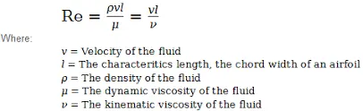
Reynolds number is a dimensionless quantity that is used to determine the type of flow pattern as laminar or turbulent while flowing through a pipe. Reynolds number is defined by the ratio of inertial forces to that of viscous forces.
Procedure:
Part-1:
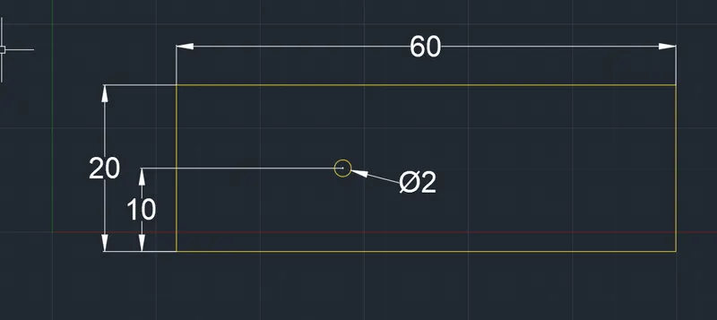
Using space claim a sketch is drawn with the below said dimension and Surafce pull option used to create a surface out of this sketch.
Once the surface is completed, Mesh module is started from Ansys workbench.
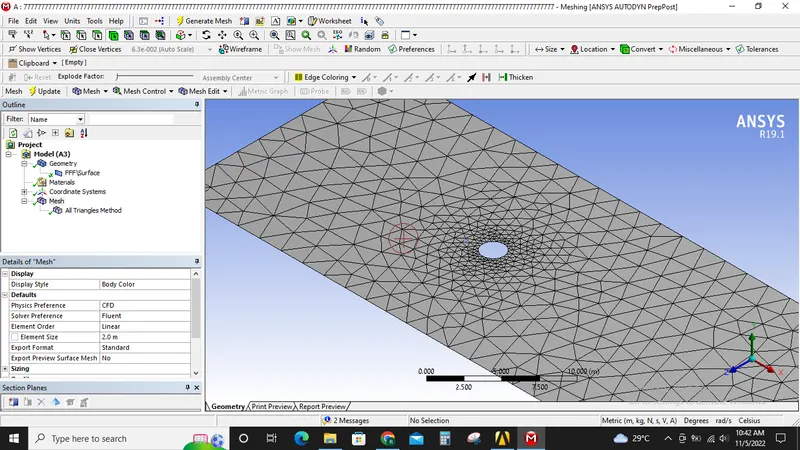
After inserting the surface is meshed with mesh length of 2 Meters.
Inlet, Outlet, Symmetry and Wall boundary conditions are created.
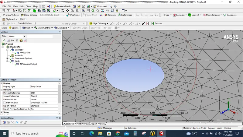
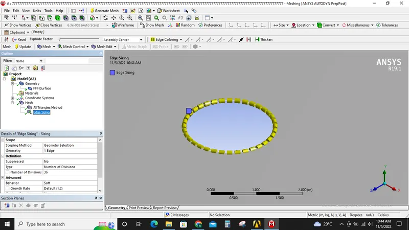
Now when examining the cylinder the cylinders surface is not smooth, so edge sizing is used to divide the cylinders surface into 36 edges so a smooth surface is obtained.
Now the mesh is updated. To capture the physics around the cylinder with the good accuracy inflation layers is used.
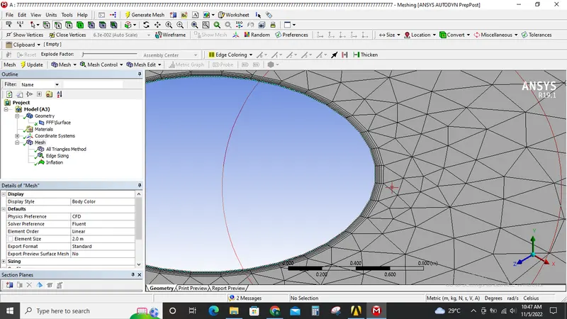
6 inflation layers with 5 mm and 1.2 mm increment in used. Now the mesh is updated.
Now the mesh module is closed and fluent module in opened. Meah quality check is performed and it it found ok.
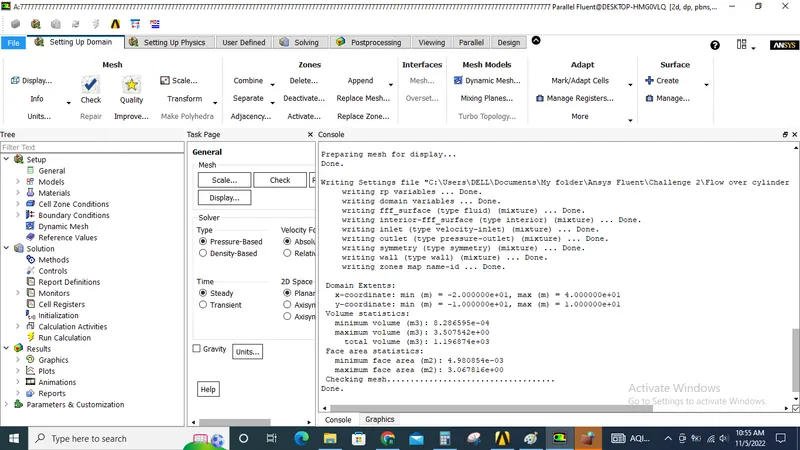
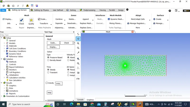
Under setting up physics steady state laminar flow is selected.
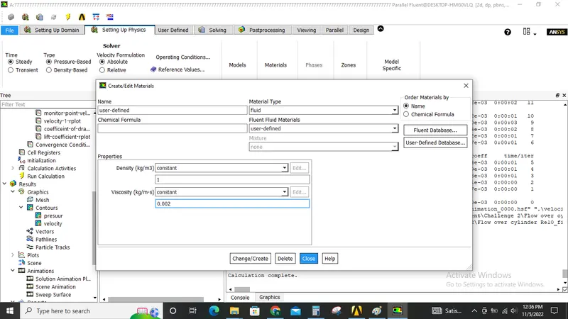
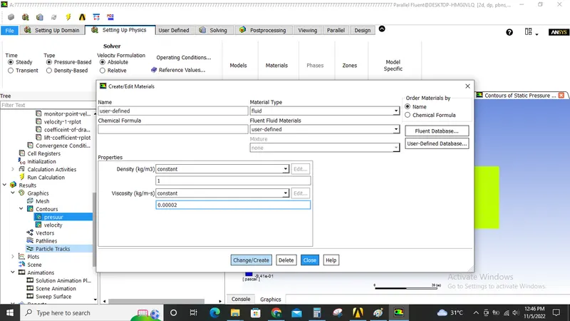
User defined material is created with density 1kg/m3 and Re=100.
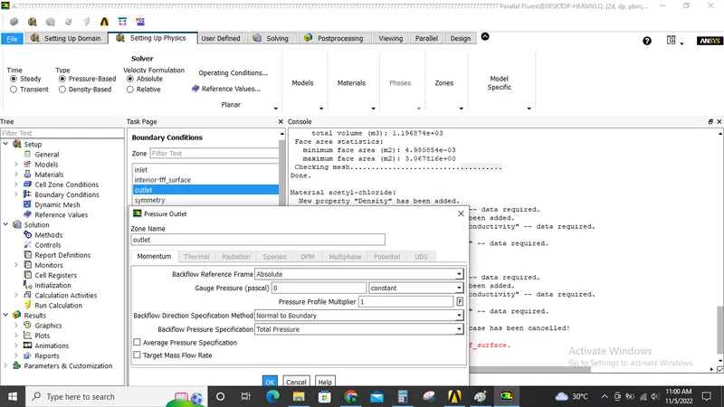
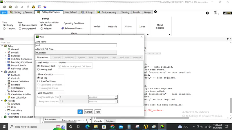
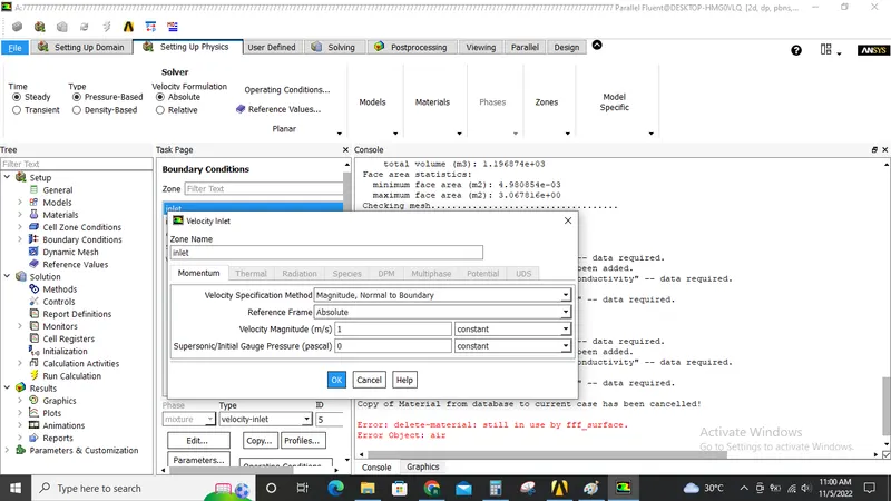
Inlet velocity of 1m/s, presuure oulet and defaul wall functions are used for inlet boundary conditions.
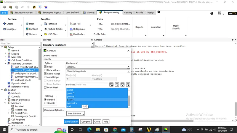
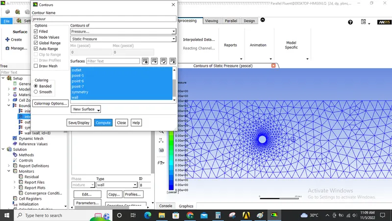
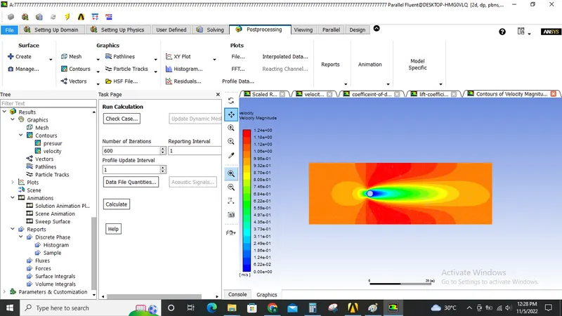
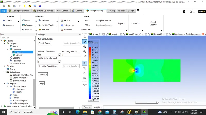
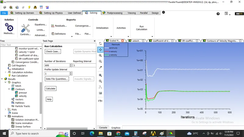
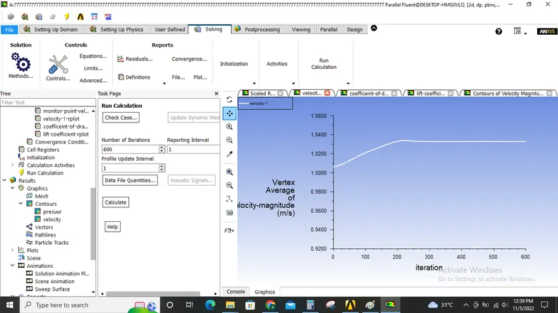
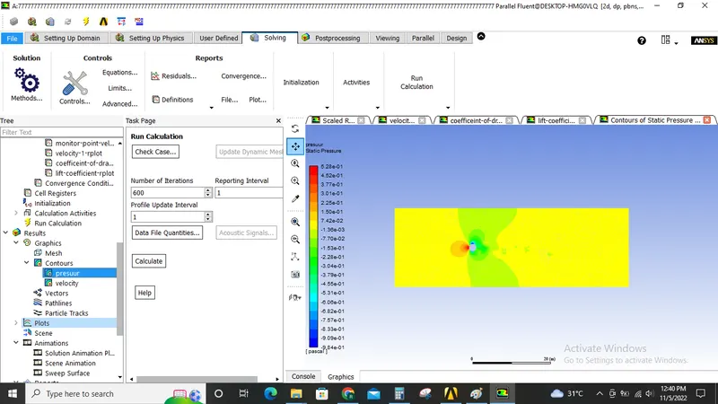
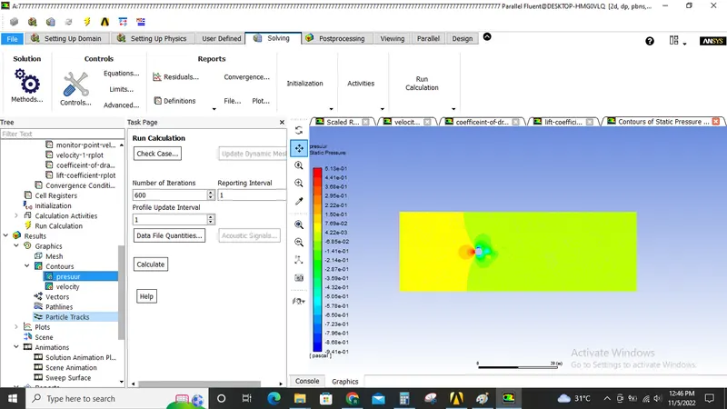
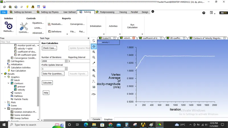
Monitor points and velocity and pressure contours are created as shown below.
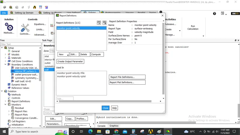
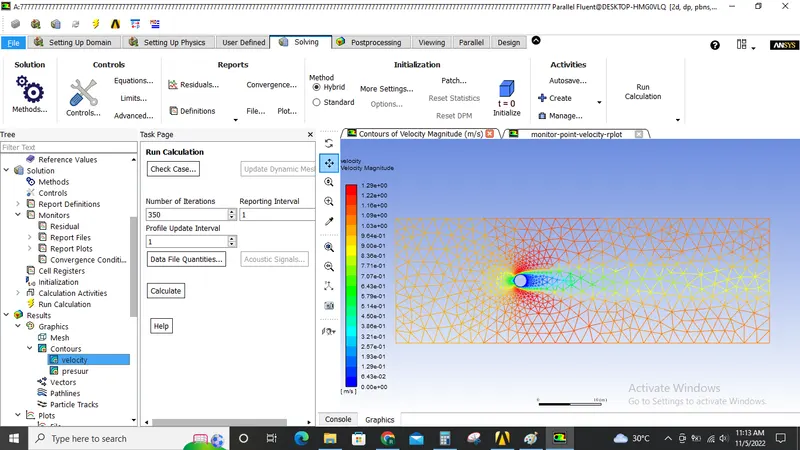
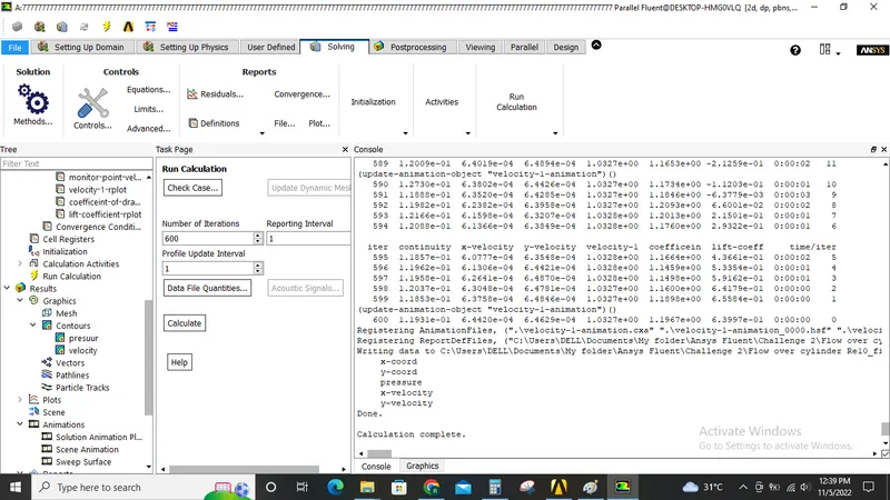
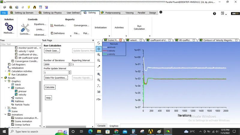
The solution is initialised and the simulation ran for 350 iterations no vortices are abserved.
So the mesh size is decreaed to 0.25 metres.
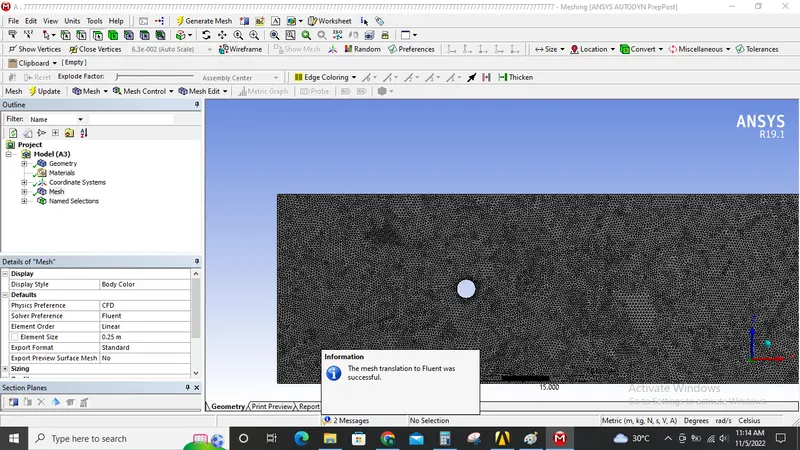
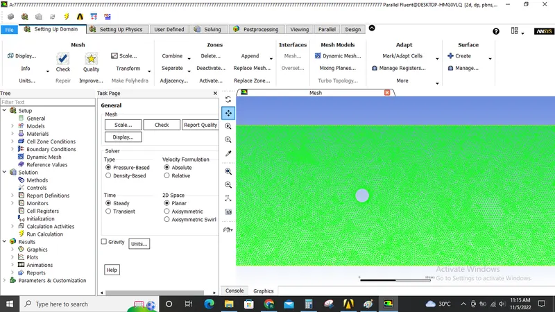
Now the solution is initialised again and simulation is run for 350 iterations.
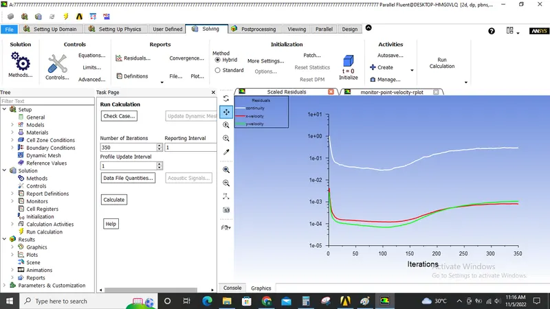
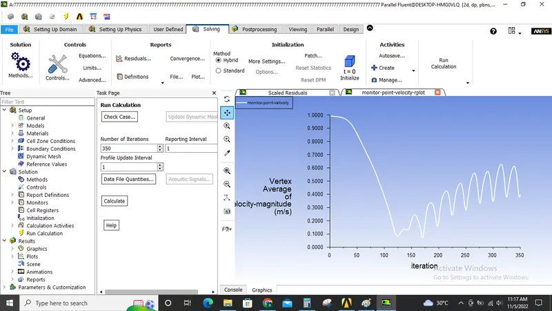
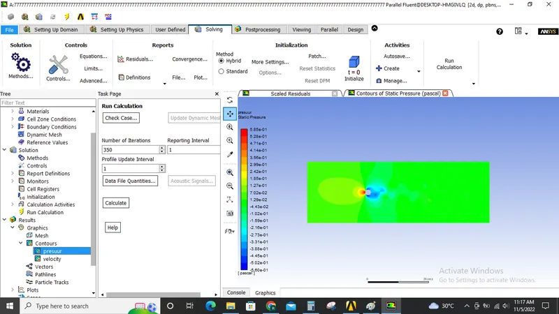
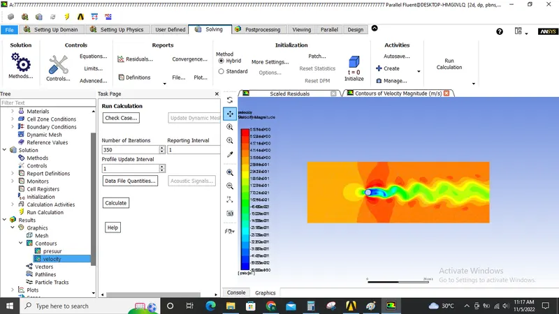
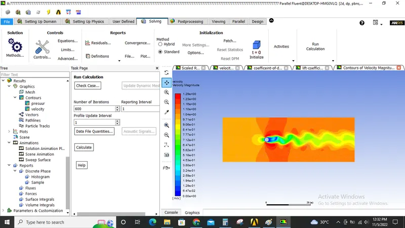
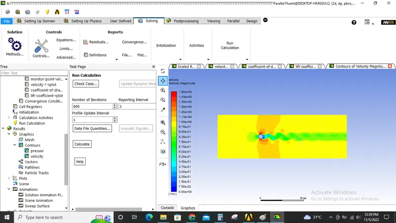
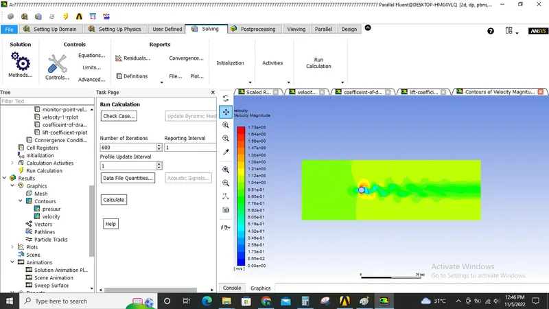
Now vortex shedding is abserved after 125 simulations.
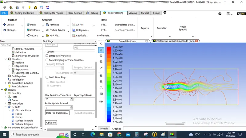
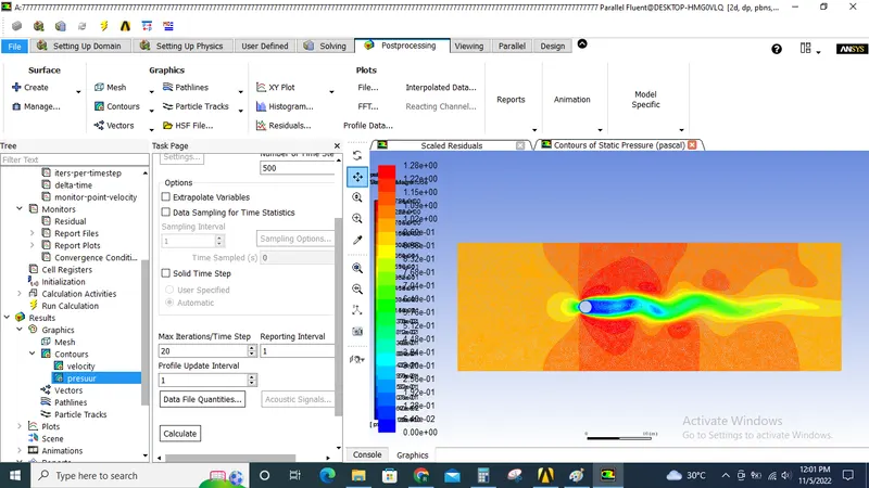
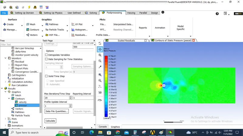
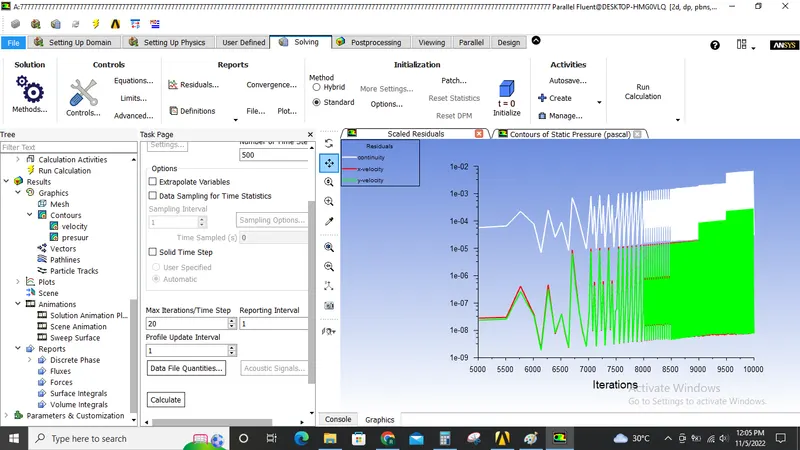
Now the same silmutaion is run as transient state simulations with time step of 0.1 and 500 time steps.
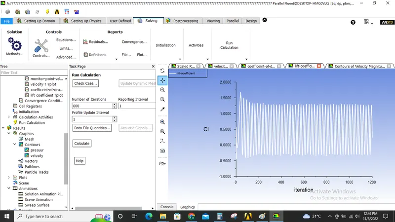
The results are shown below.
strouhal number:
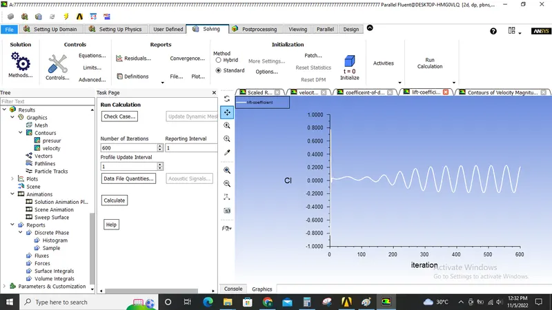
f = number of cycles/time = `1/(160-154)` = 0.166
strouhal number = `(f*L)/v` = `(0.166X2)/1`= 0.332
Part-2: Now the above steps are repeated for steady state simulation with Reynolds number set to 10,100,1000,10000 & 100000 for the user defined materials.
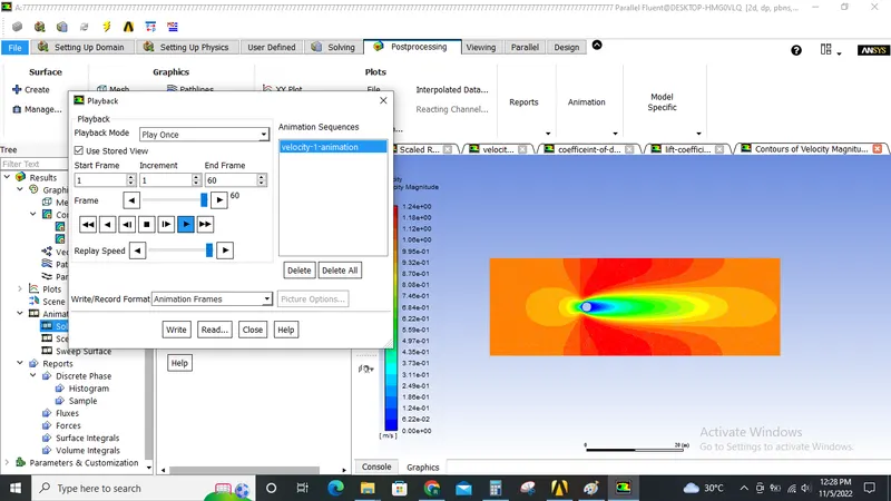
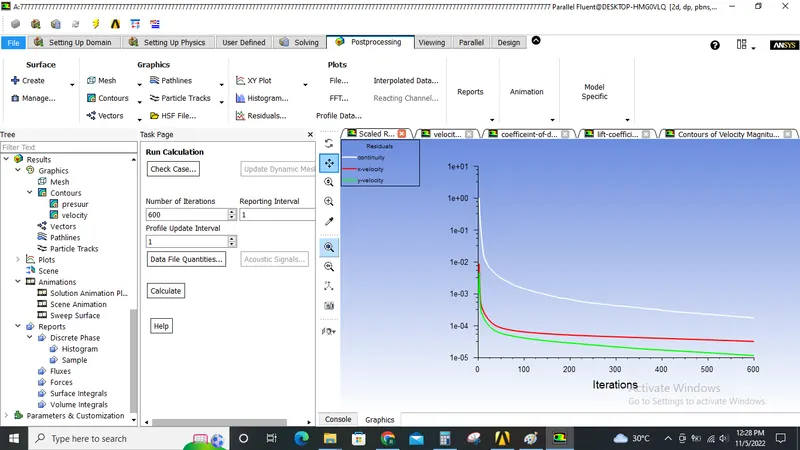
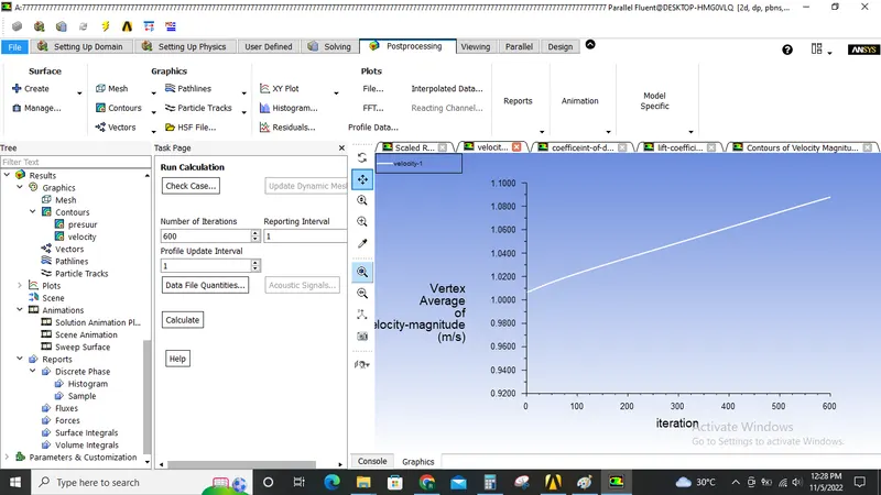
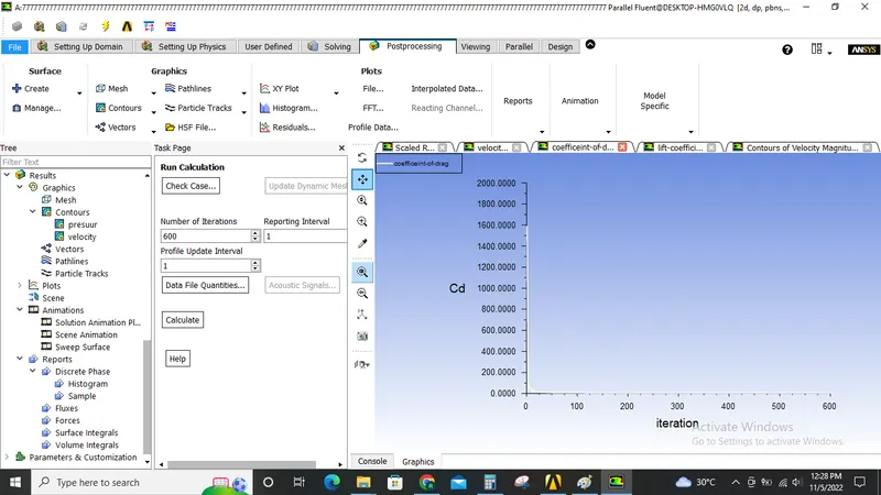
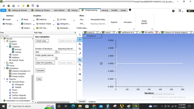
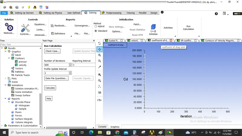
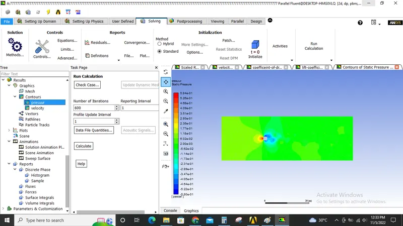
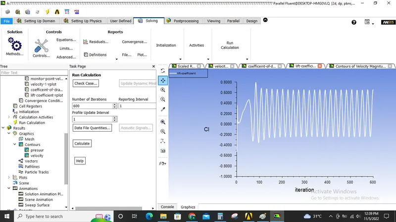
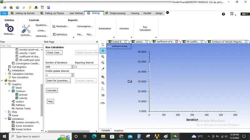
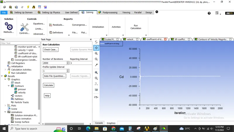
The resulta are shown below.
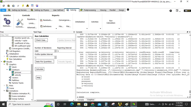
Re=10.
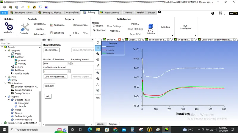
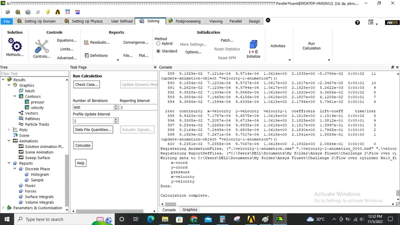
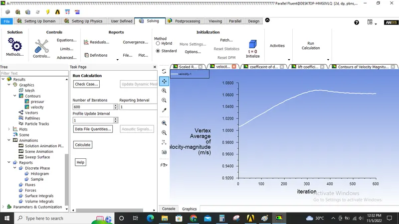
Re=100.
Re=1000.
Re=10000.
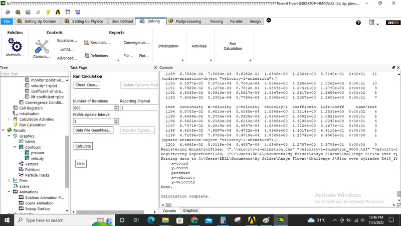
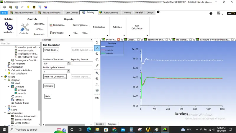
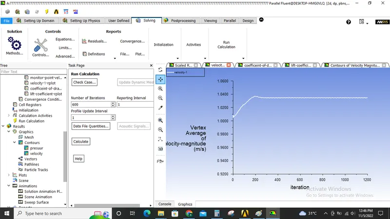
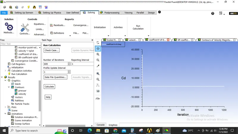
Re=100000.
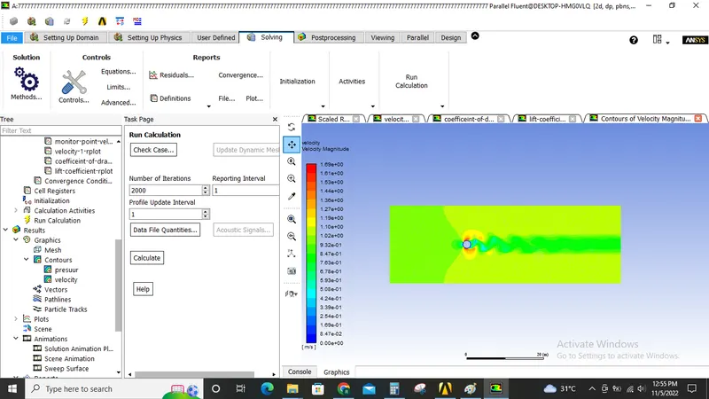
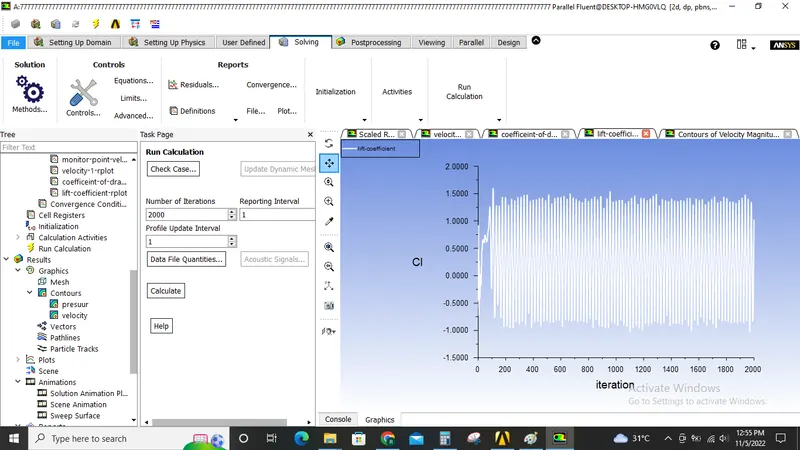
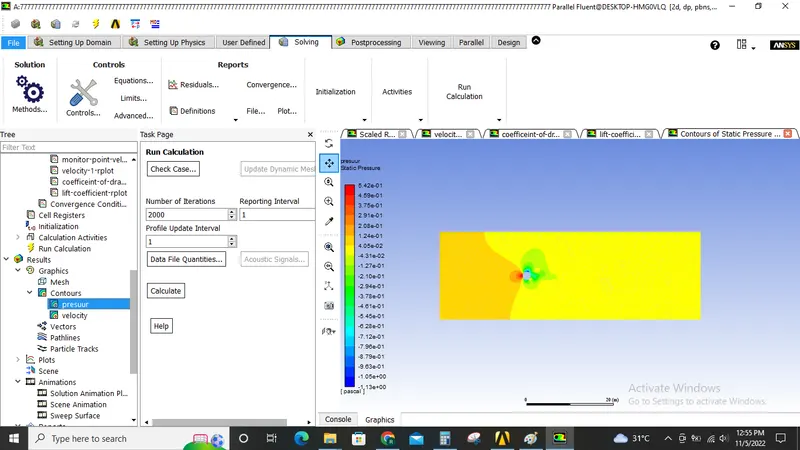
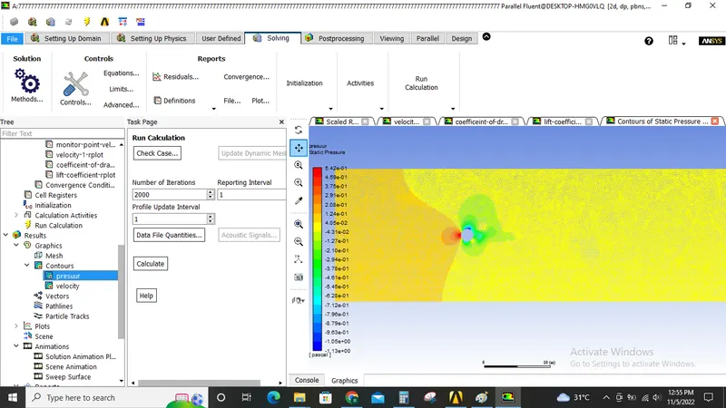
Conclusion:
As seen abserved from the abpve images it is concluded that,
- As the reynolds number increases Drag coefficient Decreases and lift coefficient increases.
- Transient state capture more accurate vortex sheding than steady state solving.