Week 2 - Flow over a Cylinder.
Aim: To simulate the flow around the cylinder to capture the effect of the vortex shedding at the back of the cylinder.
Introduction:
The flow around the cylinder has opened the path for studying the flow around the complex shape bodies that still keep their external flow properties the combination of flow properties around the simple bodies like flow around the flat plates, cylinders, ellipses, etc. The aim of this project is to describe the flow around the cylinder using the analysis of Ansys fluent.
Drag force around the bodies for the external flows express a permanent challenge for the design engineers of aerospace, automobile, and ship construction. In most cases, the design shapes are very complex so the best way to solve those issues is by comparing them with the simpler shapes simulation.
In this simulation, we have done the simulation for both the steady as well as transient study.
SPACECLAIM
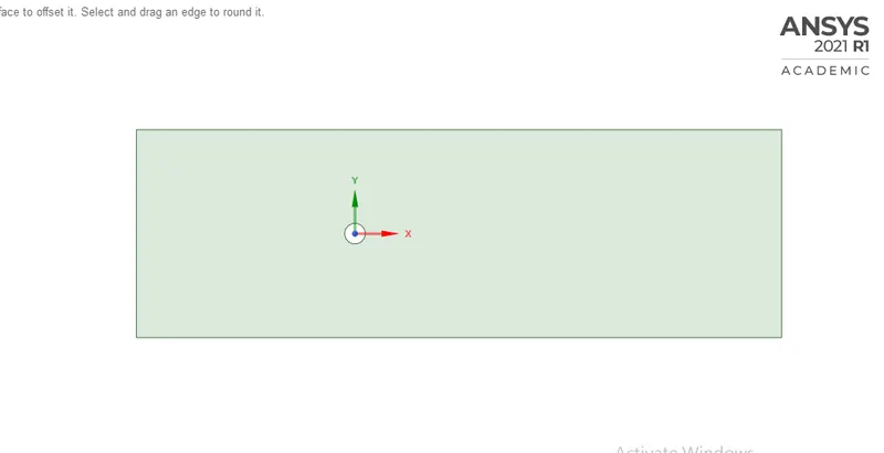
Geometry setup and mesh for the simulation.
MESHING
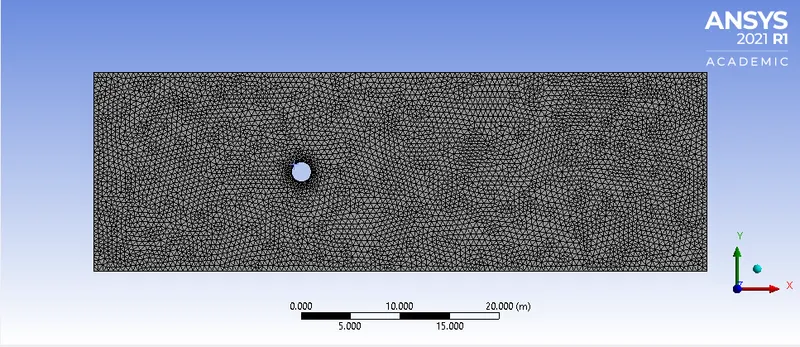
For the meshing, we have selected the triangles for the overall meshing. The boundary of the cylinder is divided into 36 divisions with the help of the sizing option and the curvature is captured. The inflation layers are also created so the mesh around the cylinder walls looks like the body-fitted mesh and the flow properties around the cylinder are measured accurately.
Named selections:Names are given to the various parts of geometry;inlet_x,outlet_x,cylinder_walls,symmetry_walls.
FLUENT
The viscous model for the simulation is chosen laminar. The new material is created of density 1 kg/m3 and the viscosity is 0.05 kg/ms.The simple solution method is chosen.
For varying the Re inlet velocity is modified every time.
for the correct values of drag and lift coefficient, the reference values have to be provided which have to be updated every time of the simulation.
After
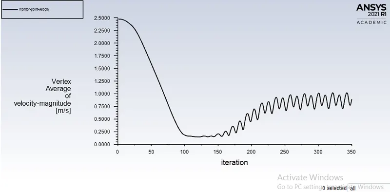
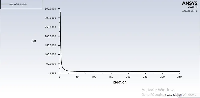
CASE 1)steady-state simulation with Re=100.
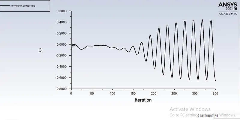
plots and the counters for 350 iterations.
Monitor point velocity plot.
Coefficient of drag.
Coefficient of lift.
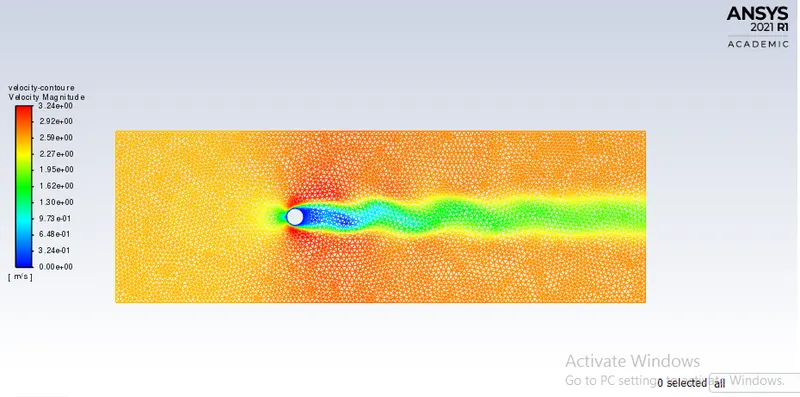
Velocity contour
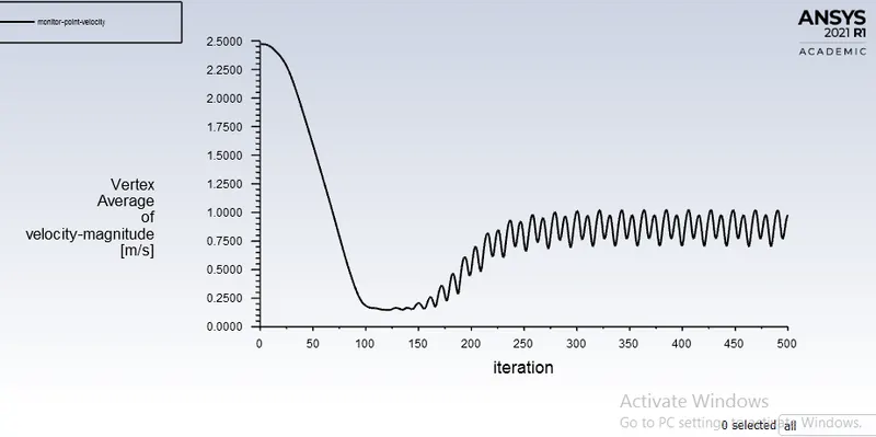
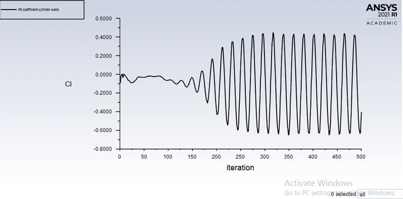
plots and contours for 500 iteration
monitor point velocity
coefficient of lift
simulation at Re=1000
plots for 500 iteration
monitor point velocity coefficient of drag
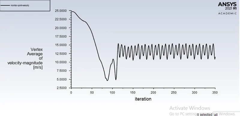
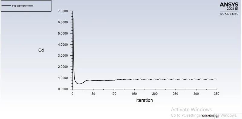
coefficient of lift pressure contour
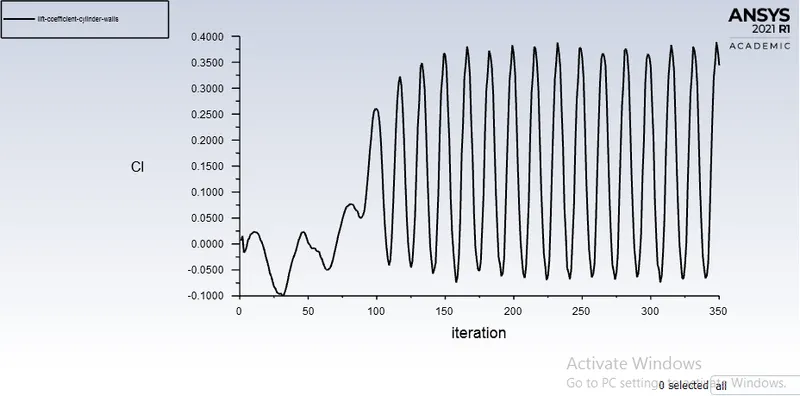
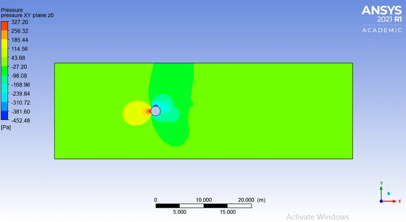
velocity contour
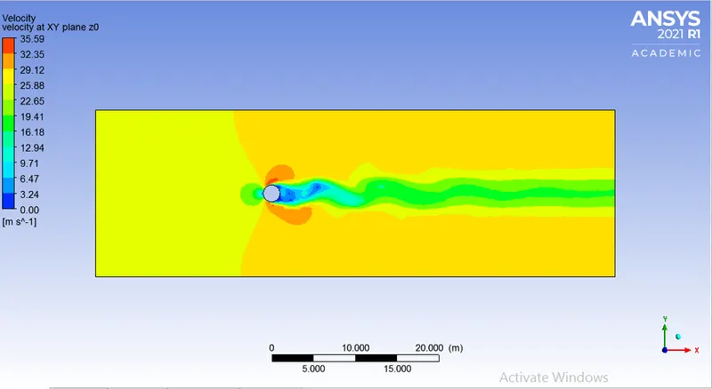
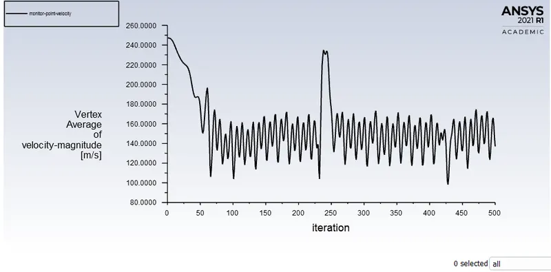
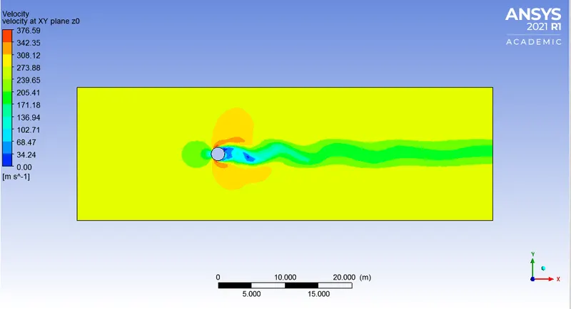
Simulation at Re=10000
monitor point velocity coefficient of lift
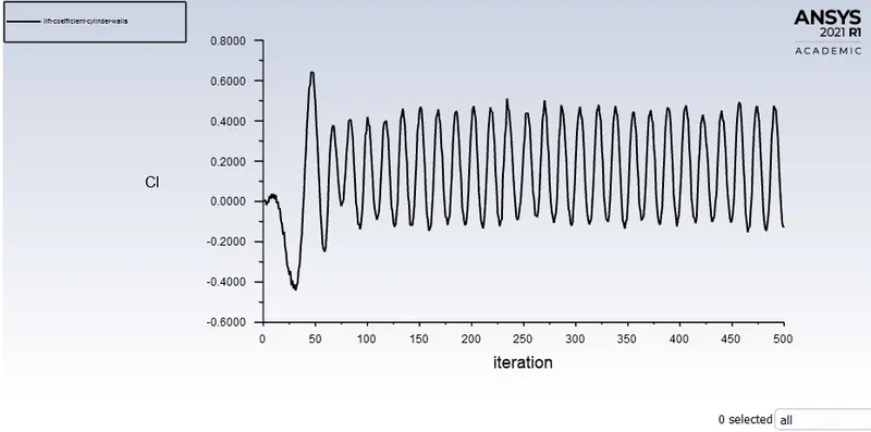
velocity contour pressure contour
SIMULATION OF THE TRANSIENT FLOW OVER THE CYLINDER
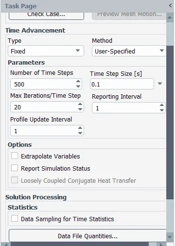
The geometry and the meshing is the same for transient flow simulation but the transient method is choose to solve the governing equation.
The time step size and the number of time steps are chosen as below.
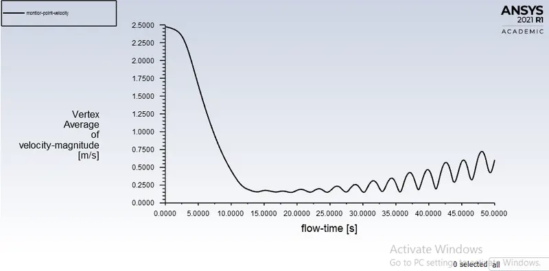
monitor point velocity contour
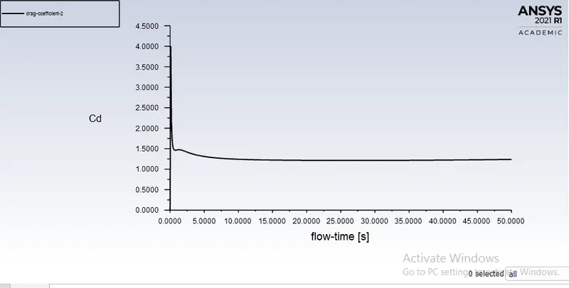
coefficient of drag
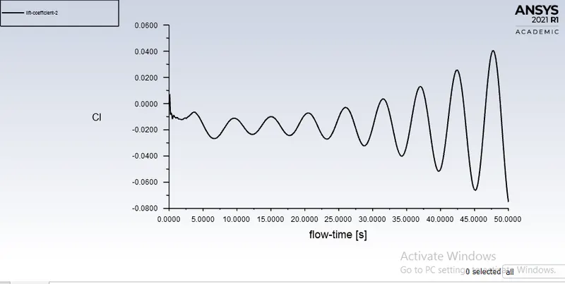
coefficient of lift
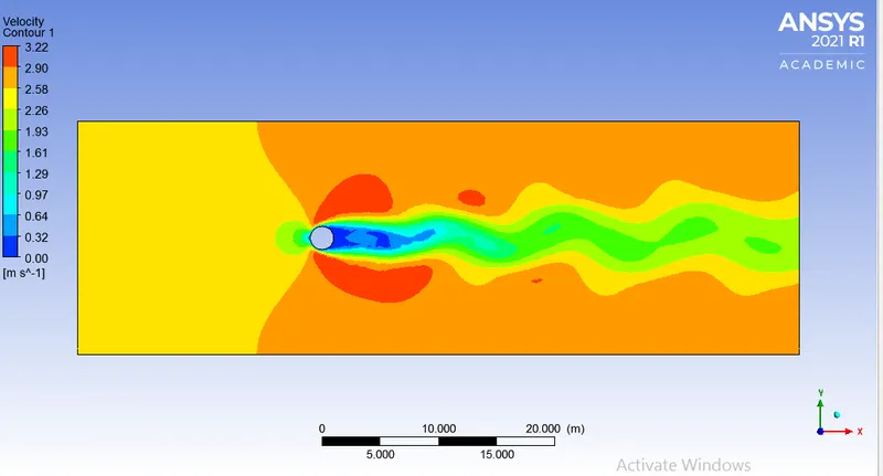
velocity contour
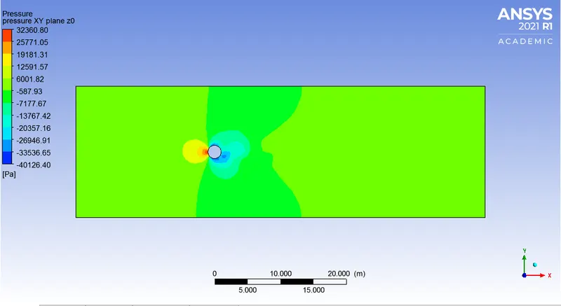
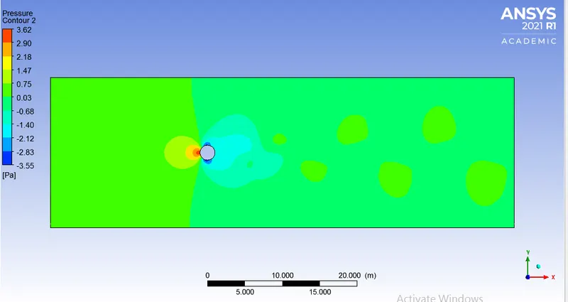
pressure contour
Strouhal number calculation
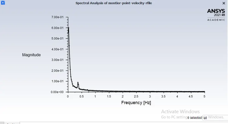
`st=(f*D)/U`
=0.0115
RESULTS FROM THE SIMULATION
| steady Re=100 | steady Re=1000 | steady Re=10000 | unsteady Re=100 | |
| Cd | 1.2559 | 0.9016 | 0.8217 | 1.2373 |
| Cl | 0.0320 | 0.1863 | 0.1791 | -0.0440 |
| monitor point velocity | 0.9010 | 12.9831 | 145.098 | 0.4824 |
CONCLUSION
1)from the results, we can see that the coefficient of drag decrease with an increase in Re.
2)We can see the vortex shedding for the flow behind the cylinder in velocity contour as well as from the plot of monitor point velocity which is fluctuating with iteration, we have to give some time to simulate the flow to obtain the complete phenomena of vortex shedding to develop in the flow region.