otto cycle code using GNU octave
Aim: To write a programme in octave which can solve otto cycle,create a pv diagram and calculate the efficiency.
Introduction to the otto cycle
An Otto cycle is an idealized thermodynamic cycle that describes the functioning of a typical spark ignition piston engine. It is the thermodynamic cycle most commonly found in automobile engines.
The otto cycle consists of four thermodynamic processes
1)isentropic compression process (1→2)(compression stroke)
Governing equation for this is `p*V^gamma=constant`
Where the γ is called the adiabatic index
2)constant volume heat addition (2→3)(combustion stroke )
Governing equation for this is heat supplied =`m*Cv*deltaT`
Cv is the specific heat at constant volume
3)isentropic expansion process(3→4)(power stroke)
Governing equation for this is`p*V^gamma=constant`
4)constant volume heat rejection (4→1)(expansion stroke)
Governing equation for this is heat rejected =`m*Cv*deltaT`
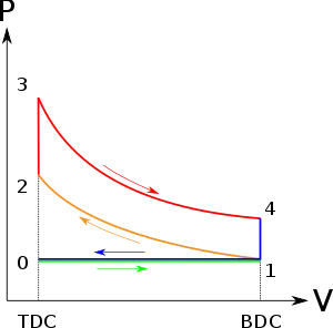
Some other thermodynamic relation used in the code
Ideal gas equation`p*V =m*R*T`
P is the absolute pressusre in N/m2
V is the volume in m3
m is the mass of the system
R is characteristics gas constant
T is the absolute temperature
Steps to write a octave code
- By the commands I clear all previous variables as well as the previous plots and clear command line.
-
clear all close all clc - Description of the programme by comments
-
%otto cycle using octave - Required inputs are given like gamma,heat supplied,compression ration
-
%inputs gamma=1.4; %adiabatic index q=1800; %heat supplied is given %in kj/kg r_k=7; - Defining engine geometric properties like bore ,stroke length ,connecting rod length
-
%engine geometric parameters sequence vise (bore,stroke,con_rod) bore=0.1; %in meter stroke=0.15; %in meter con_rod=0.1; %in meter - Calculating swept volume and clearance volume
-
%calculating the swept volume and clearance volume V_s=(pi/4)*bore^2*stroke; V_c=V_s/(r_k-1) - Defining the state of the system by defining and calculating P1 V1 and T1
-
%state variable at state_1 p1=100000; %in pascal T1=300; %in kelvin V1=V_c+V_s; state_1=[p1 V1 T1] - The process 1 to 2 is isentropic process so the state variable at state 2 is calculated by
-
%state variable at state_2
                           %finding value of p2
                           %p2*v2^gamma =p1*v1^gamma
                           %p2=p1*(v1/v2)^gamma =p1*(r_k)^gamma
                           p2=p1*(r_k)^gamma;
                           V2=V_c;
                           %finding value of T2
                           %p2*V2/T2=p1*V1/T1
                           T2=p2*V2*T1/(p1*V1);
                           constant_c=p1*V1^gamma
V2 is the clearance volume
For finding the values of p2 and T2
8) For plotting the variation of volume and pressure the function engine kinematics is called into the script with start crank angle 0 to end crank angle 180.
%calling a function engine kinematics
                           %output of function is stored in variable V_compression
             %for plotting the curve on the p_v
             V_compression=engine_kinematics(bore,stroke,con_rod,r_k,0,180)
             p_compression=constant_c./V_compression.^gamma
             V2=V_c
                           state_2=[p2 V2 T2]
9)the results of function is stored in variable v_compression for process 1to 2,the values of
P_compression are calculated by above equation.
10)Process 2 to 3 is constant volume process
the state variables at 3 are calculated by following equation
heat supplied is given so the value of T3 is given by (heat supplied/Cp)+T2
the value of P3 is given by = p2*(T3/T2)
 %state variable at state_3
                                    %finding value of T3 ,heat supplied is given
                                    %q=C_v(T3-T2)
                                    T3=(1800/(0.718))+T2
                                    %finding value of p3
                                    V3=V2;     %constant volume process
                                    %p2/T2=p3/T3
                                    p3=p2*(T3/T2);
                                    state_3=[p3 V3 T3]
11) The process3 to 4 is isentropic process so the state variable at state 4 is calculated.
   %state variable at state_4
                                                   %finding value of p4
                                                   %p4*V4^gamma =p3*V3^gamma
                                                   p4=p3*[1/(r_k)^gamma];
                                                   V4=V1;
                                                   %finding value of T4
                                                   %p3*V3/T3=p4*V4/T4
                                                   T4=p4*V4*T3/(p3*V3);
                                                   %T4=800;
For plotting the variation of volume and pressure the function engine kinematics is called into the script with start crank angle 360 to end crank angle 540
constant_d=p3*V3^gamma
                                                   %for plotting the curve on the p_v
                                                   V_expansion=engine_kinematics(bore,stroke,con_rod,r_k,360,540)
                                                   p_expansion=constant_d./V_expansion.^gamma
12)at last air standard efficiency is calculated.
 %calculating the  air standard efficiency
               %n=1-1/(r_k)^(gamma-1)
               n=1-1/(r_k)^(gamma-1)
13)the state points are denoted with the help of marker o.and the curve of process 1to2 and 3 to 4 is plotted with the value of p_compression and v_compression and p_expansion and v_ expansion.
hold on
   plot(V1,p1,'color','r','marker','o')
   plot(V2,p2,'color','r','marker','o')
   plot(V3,p3,'color','r','marker','o')
   plot(V4,p4,'color','r','marker','o')
 plot(V_compression,p_compression)
   plot(V_expansion,p_expansion)
14)the line are created with the help of plotting of line between the two points
plot([V2 V3],[p2 p3])
   plot([V4 V1],[p4 p1])
15)xlabel and ylabel and the title is given to the graph for the better understanding of the graph.
Output or plots of the code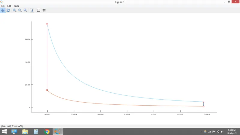
conclusion
1)the efficiency of the otto cycle is 54.084 %