Week 2 - Flow over a Cylinder.
AIM:
To simulate flow over a cylinder & to explain the phenomenon of Von Karman vortex street.
Part 1:
a) To simulate with steady simulation for Reynold's number of 100.
b) To simulate with unsteady/transient simulation for Reynold's number of 100 with Strauhal number.
Part 2:
a) To run a steady state simulation along with calculating Coeffecient of drag & Coeffecient of lift for flow over cylinder for Reynold's number = 10; 100; 1000; 10000; 100000.
b) To discuss the effect of Reynold's number on coeffecient of drag.
c) To validate results with standard literature(error must be within 5%).
Expected outcomes:
a) To show the flow has converged in case 1 & case 2.
b) To show plots of Cd & Cl.
c) To show vortex shedding behind the cylinder.
d) Mention of references.
IMPORTANT TERMS:
1. Reynold's number:
A dimensionless number used in fluid mechanics to indicate whether fluid flow past a body or in a duct is steady or turbulent.
The Reynolds number (Re) is a dimensionless number, named after the Osborne Reynolds , defined as the ratio of inertial forces to viscous forces.
That is, the Reynolds number is given as:
where, D is the diameter of the tube (m),
v is the velocity of the fluid (m/s),
`nu`is the kinematic viscosity of the fluid (`m^2/s`).
2. Drag Coefficient:
The drag coefficient (`C_d`) is a dimensionless quantity that is used to determine the drag or resistance of an object in a fluid environment, such as air or water.
The Drag coefficient is given as:
where, A is the Cross sectional area in (`m^2`)
`F_d` is the Drag force in (N)
u is the flow velocity in (m/sec)
`rho` is the density of the fluid in (`(kg)/m^3`)
3. Lift Coefficient
The lift coefficient (`C_l`) is a dimensionless quantity that is used to determine the lift of an object in a fluid environment.
The Lift coefficient is given as:
where, A is the Cross sectional area in (`m^2`)
`F_l` is the Drag force in (N)
u is the flow velocity in (m/sec)
`rho` is the density of the fluid in (`(kg)/m^3`)
4. Strouhal number:
The Strouhal Number is a dimensionless value useful for analyzing oscillating unsteady fluid flow dynamics problems.
The Strouhal Number can be important when analyzing unsteady, oscillating flow problems. The Strouhal Number represents a measure of the ratio of the inertial forces due to the unsteadiness of the flow or local acceleration to the inertial forces due to changes in velocity from one point to an other in the flow field.
The Strouhal Number can be expressed as
`St = (omega l) / v`
where, St = Strouhal Number
`omega`= oscillation frequency
l = characteristic length
v = flow velocity
Theory:
Reynold's number derivation:
The dimensionless Reynolds number predicts whether the fluid flow would be laminar or turbulent referring to several properties such as velocity, length, viscosity, and also type of flow. It is expressed as the ratio of inertial forces to viscous forces and can be explained in terms of units and parameters respectively, as below.
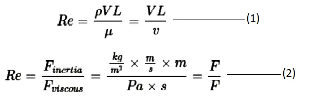
where `rho [(kg)/m^3]` is the density of the fluid, V `(m/s)` is the characteristic velocity of the flow, and L (m) is the characteristic length scale of flow. Equation 2 is the derivation of units at which the Reynolds number is specified as non-dimensional. Variations of the Reynolds number are shown in equation 1 where `mu(Pa×s)` is the dynamic viscosity of fluid and `nu (m^2/s)` is the kinematic viscosity. The transition between dynamic and kinematic viscosity is as follows:
`nu=mu/rho`
Fluid, flow and Reynold's number:
The applicability of the Reynolds number differs depending on the specifications of the fluid flow such as the variation of density (compressibility), variation of viscosity (Non-Newtonian), being internal or external flow, etc. The critical Reynolds number is the expression of the value to specify transition among regimes which diversifies regarding the type of flow and geometry as well. Whilst the critical Reynolds number for turbulent flow in a pipe is 2000, the critical Reynolds number for turbulent flow over a flat plate, when the flow velocity is the free-stream velocity, is in a range from `10^5` to `10^6`.
The Reynolds number also predicts the viscous behavior of the flow in case fluids are Newtonian. Therefore, it is highly important to perceive the physical case to avoid inaccurate predictions. Transition regimes and internal & external flows are the basic fields to comprehensively investigate the Reynolds number. Newtonian fluids are fluids that have a constant viscosity. If the temperature stays the same, it does not matter how much stress is applied on a Newtonian fluid; it will always have the same viscosity. Examples include water, alcohol and mineral oil.
External flow:
External flow at which mainstream has no district boundaries is alike to internal flow that also has a transition regime. Flows over bodies such as a flat plate, cylinder and sphere are the standard cases used to investigate the effect of velocity throughout the stream. In 1914, German scientist Ludwig Prandtl discovered the boundary layer, which is partially the function of the Reynolds number, covering surface through laminar, turbulent and also transition regimes. The flow over a flat surface is shown below with regimes where `x_c` is the critical length for transition, L is the total length of the plate and u is the velocity of the free streamflow.
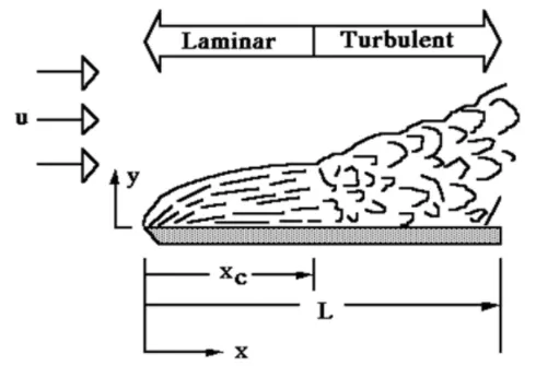
In general, the boundary layer dilates with movement through x direction on plate that eventually results in unstable conditions where the Reynolds number increases simultaneously. The critical Reynolds number for flow over flat plate surface is:

which depends on the uniformity of the flow over the surface. Yet while the critical Reynolds numbers for regimes are virtually specified for internal flow, it is hard to detect them for an external flow which diversifies the critical Reynolds number regarding geometry. Furthermore, apart from internal flow, boundary layer separation is an anomalous issue for external flow where several ambiguities are encountered to generate a reliable numerical model with respect to a physical domain.
Von Karman vortex street:
In fluid dynamics, a Kármán vortex street (or a von Kármán vortex street) is a repeating pattern of swirling vortices, caused by a process known as vortex shedding, which is responsible for the unsteady separation of flow of a fluid around bluff bodies.
The von Kármán vortex street is a direct result of boundary layer separation over bluff bodies. Immersed in fluid flow, any body of finite thickness will force the surrounding fluid to flow in curved streamlines around it. Towards the leading edge this causes the flow to speed up in order to balance the centripetal forces created by the curved streamlines. This creates a region of falling fluid pressure, also called a favourable pressure gradient. Further along the body, where the streamlines straighten out, the opposite occurs and the fluid flows into a region of rising pressure, an adverse pressure gradient. The increasing pressure gradient pushes against the flow and causes the slowest parts of the flow, those immediately adjacent to the surface, to reverse direction. At this point the boundary layer has separated from the body and the combination of flow in two directions induces a wake of turbulent vortices (see diagram below).
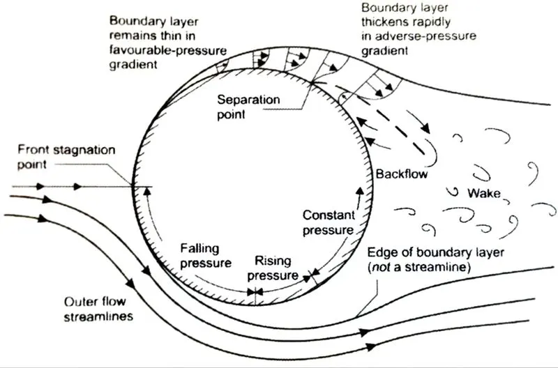
Boundary layer separation over cylinder
The type of flow in the wake depends on the Reynolds number of the flow impinging on the body,
`Re = {rho V d}/{mu}`
where `rho` is the density of the fluid, V is the impinging free stream flow velocity, d is a characteristic length of the body, e.g. the diameter for a sphere or cylinder, and `mu` is the viscosity or inherent stickiness of the fluid. The Reynolds number essentially takes the ratio of inertial forces `rho V d` to viscous forces `mu`, and captures the extent of laminar flow (layered flow with little mixing) and turbulent flow (flow with strong mixing via vortices).
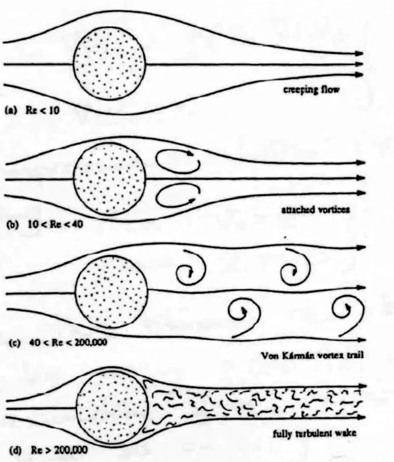
Flow around a cylinder for different Reynolds numbers
Consider the flow past an infinitely long cylinder protruding out of your screen (as shown in the figure above). For very low Reynolds number flow (Re < 10) the inertial forces are negligible and the streamlines connect smoothly behind the cylinder. As the Reynolds number is increased into the range of Re = 10-40 (by, for example, increasing the free stream velocity ), the boundary layer separates symmetrically from either side of the cylinder, and two eddies form that rotate in opposite directions. These eddies remain fixed and do not “peel away” from the cylinder. Behind the vortices the flow from either side rejoins and the size of the wake is limited to a small region behind the cylinder. As the Reynolds number is further increased into the region Re > 40, the symmetric eddy formation is broken and two asymmetric vortices form. Such an instability is known as a symmetry-breaking bifurcation in stability theory and the ensuing asymmetric vortices undergo periodic oscillations by constantly interchanging their position with respect to the cylinder. At a specific critical value of Reynolds number (Re ~ 100) the eddies start to peel away, alternately from either side of the cylinder, and are then washed downstream. As visualised below, this can produce a rather pretty effect.
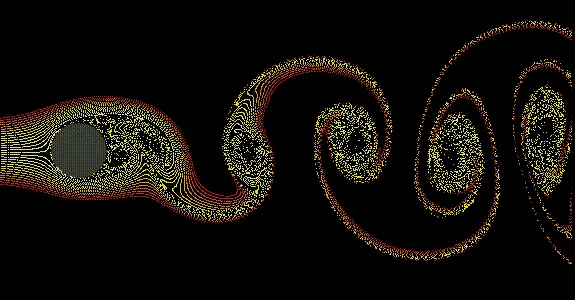
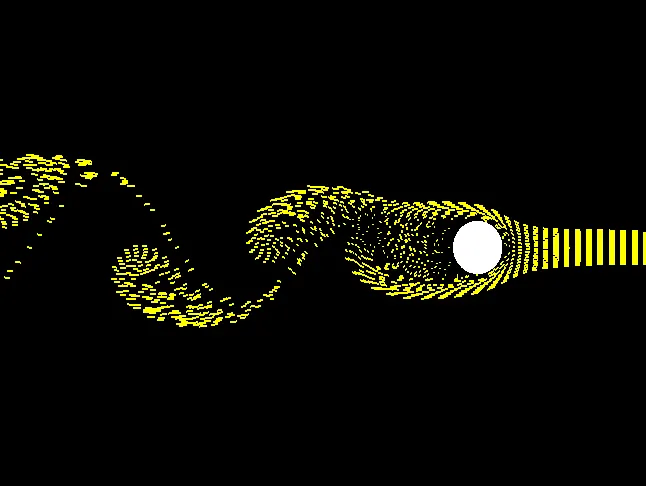
This condition of alternately shedding vortices from the sides of the cylinder is known as the von Kármán vortex street. At a certain distance from the cylinder the behaviour obviously dissipates, but close to the cylinder the oscillatory shedding can have profound aeroelastic effects on the structure. Aeroelasticity is the study of how fluid flow and structures interact dynamically. For example, there are two very important locations on an aircraft wing:
1) the centre of pressure, i.e. an idealised point of the wing where the lift can be assumed to act as a point load
2) the shear centre, i.e. the point of any structural cross-section through which a point load must act to cause pure bending and no twisting
The problem is that the centre of pressure and shear centre are very rarely coincident, and so the aerodynamic lift forces will typically not only bend a wing but also cause it to twist. Twisting in a manner that forces the leading edge upwards increases the angle of attack and thereby increases the lift force. This increased lift force produces more twisting, which produces more lift, and so on. This phenomenon is known as divergence and can cause a wing to twist-off the fuselage.
A different, yet equally pernicious, aeroelastic instability can occur as a result of the von Kármán vortex street. Each time an eddy is shed from the cylinder, the symmetry of the flow pattern is broken and a difference in pressure is induced between the two sides of the cylinder. The vortex shedding therefore produces alternating sideways forces that can cause sideways oscillations. If the frequency of these oscillations is the same as the natural frequency of the cylinder, then the cylinder will undergo resonant behaviour and start vibrating uncontrollably.
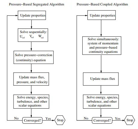
Pressure based solver:
Discretization of the Momentum Equation:

Discretization of the Continuity Equation:
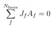
where `J_f` is the mass flux through face f, `rhov_n`

where `p_(c0) , p_(c1) and v_n,c_0 , v_n,c_1` are the pressures and normal velocities, respectively, within the two cells on either side of the face, and `hatJ_f` contains the influence of velocities in these cells. The term `d_f` is a function of `veca_P` , the average of the momentum equation `a_P` coefficients for the cells on either side of face f.
SIMULATION:
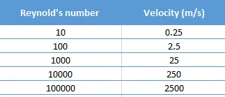
`Re=(rho v D)/mu`
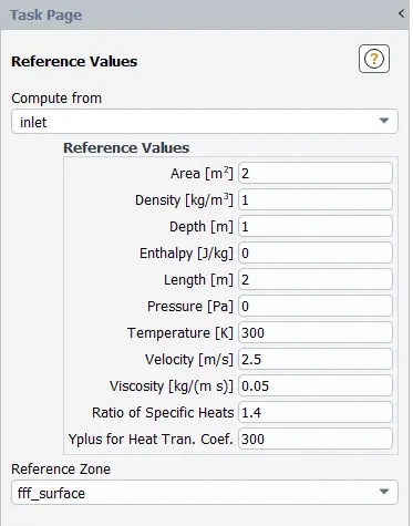
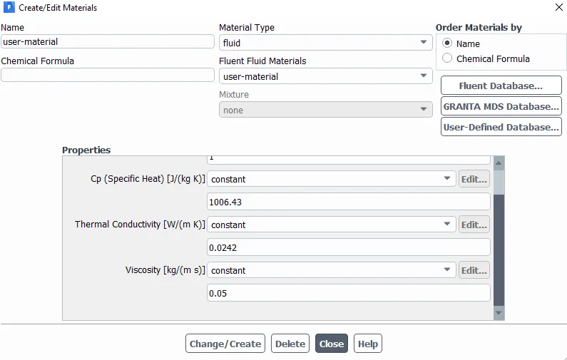
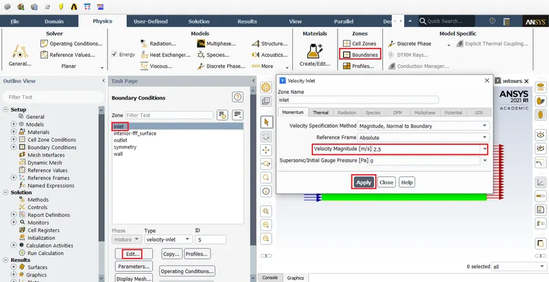
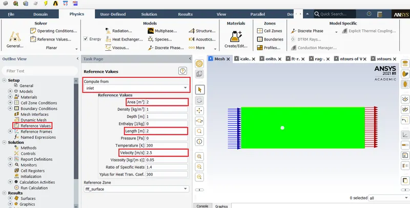
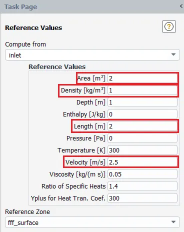
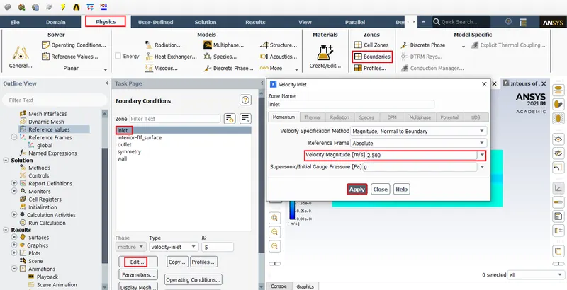
here, `mu=0.05 (Ns)/m^2`, `rho=1(kg)/m^3`, v=Velocity in m/s, D=Diameter=2m.
PART 1:
Steady state: Reynold's number 100
Geometry creation:
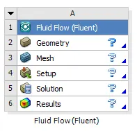
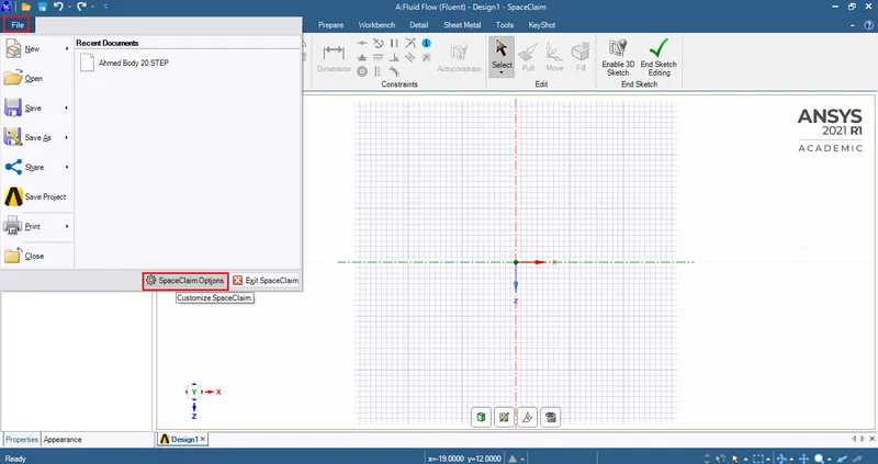
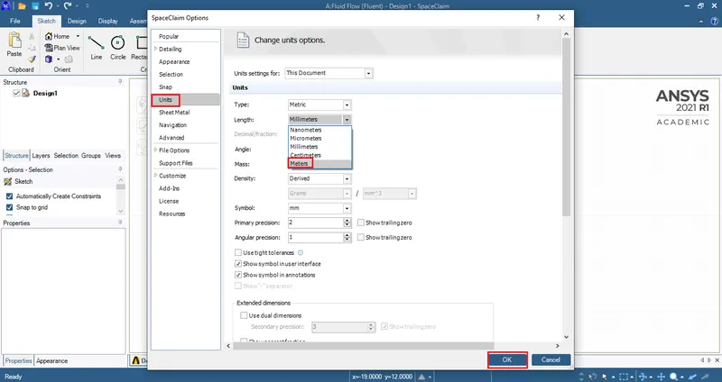
First, check whether the units are in meters.
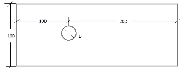
Domain measurements.
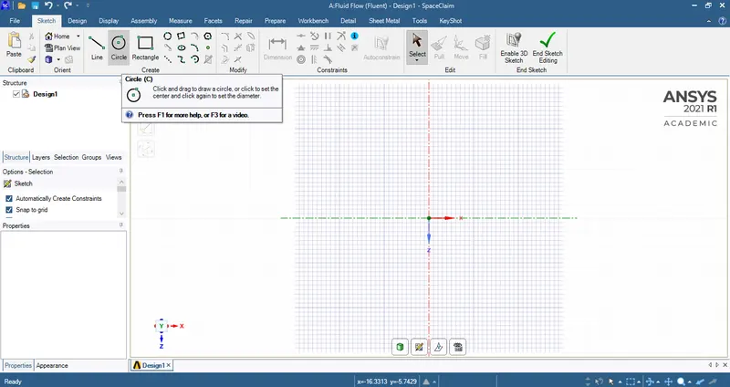
Start with drawing the circle at the origin.
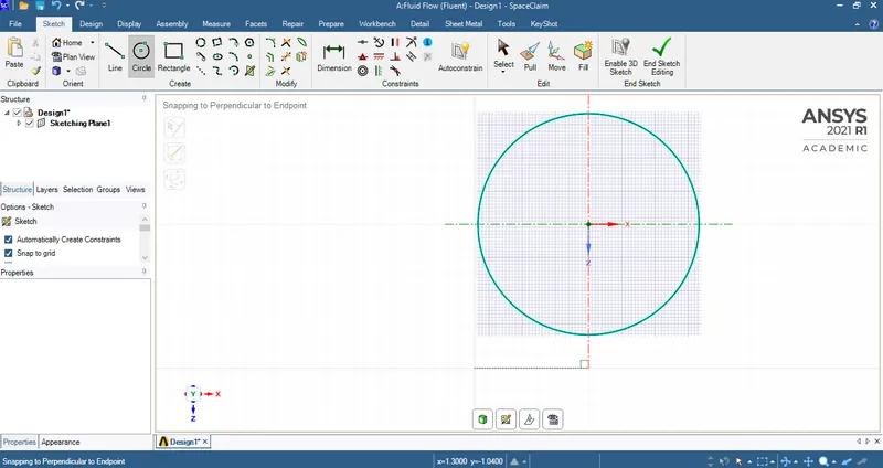
The radius has been decided to be 1 meter.
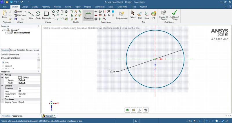
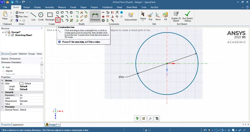
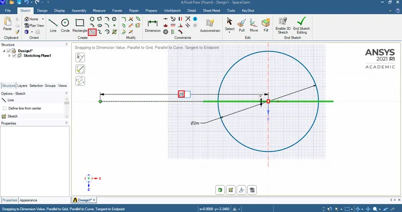
Construction lines must be used to define the boundaries of the domain.
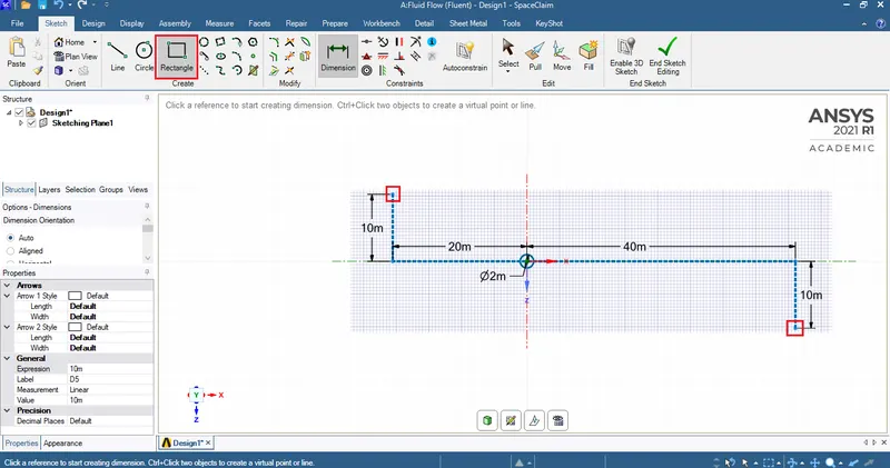
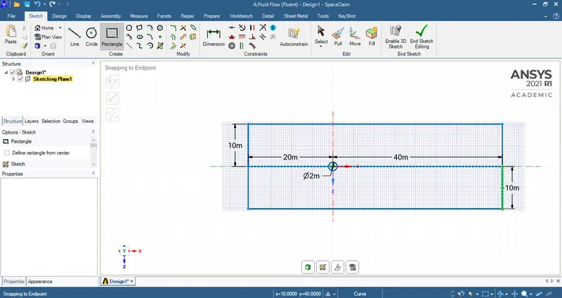
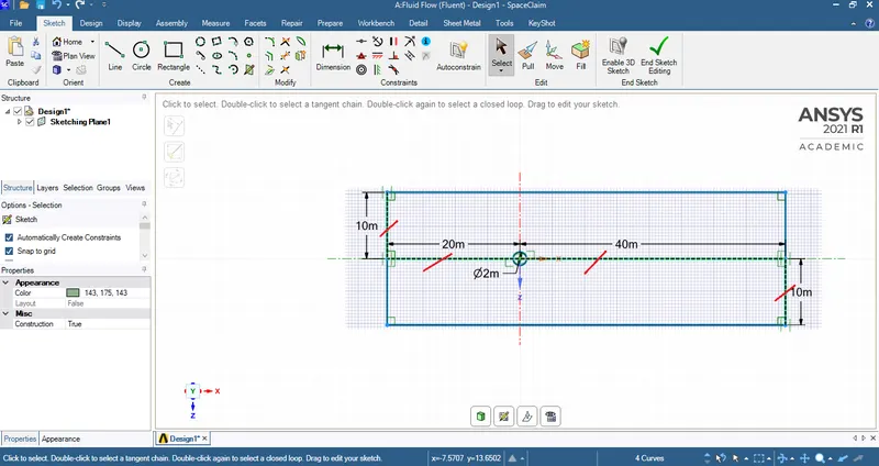
Delete the constructions that were used to draw the domain.
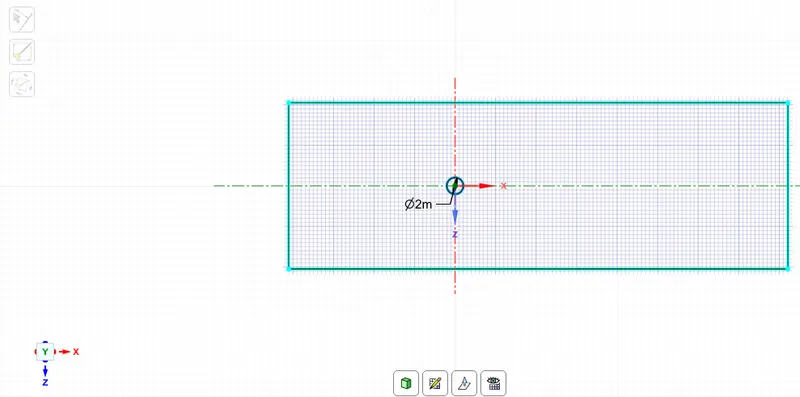
This is the finished domain.
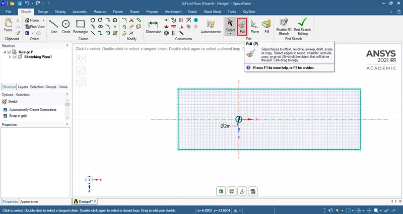
Use pull tool to fill the enclosure within domain.
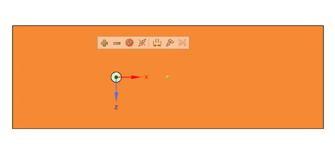
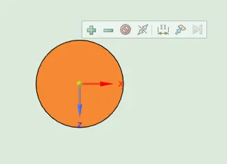
Delete the circle.
Close the geometry window and open the setup.
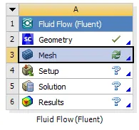
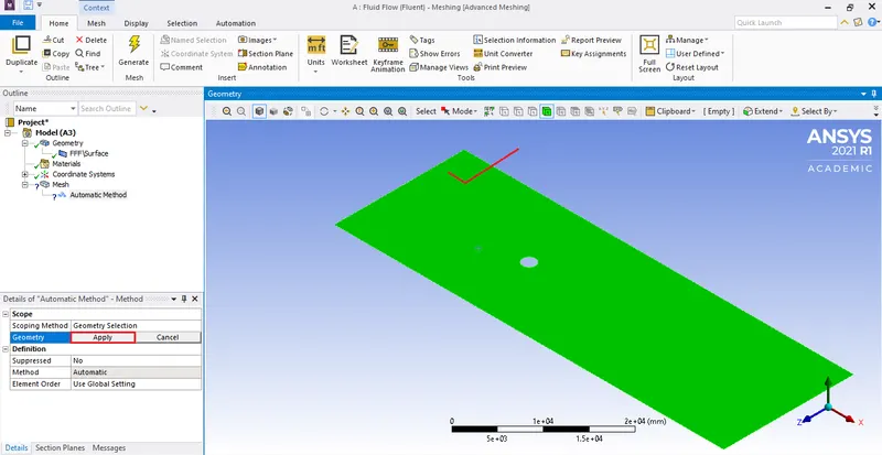
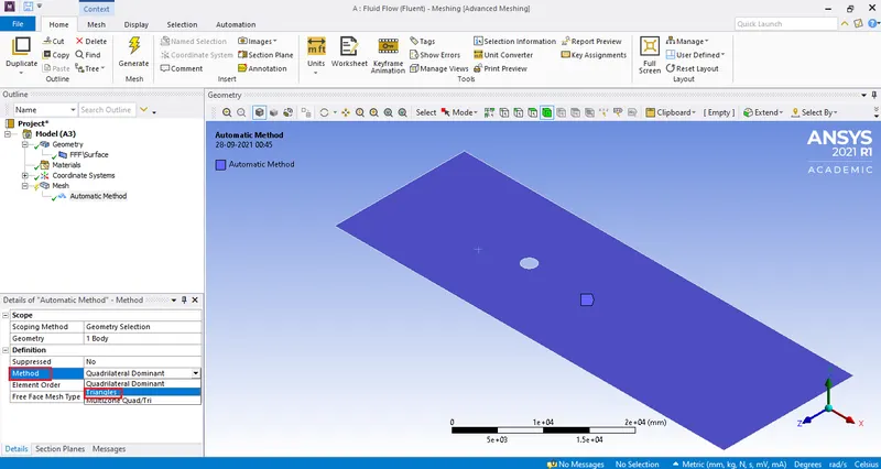
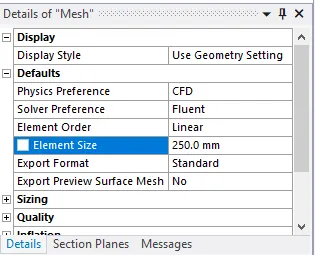
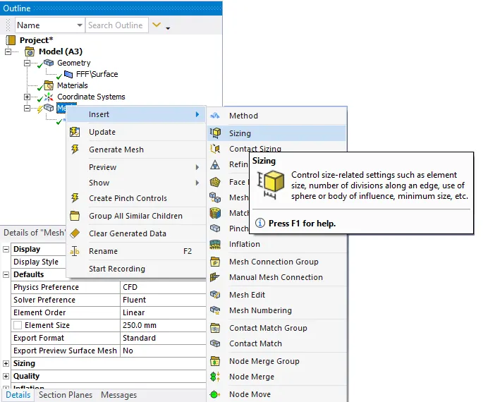
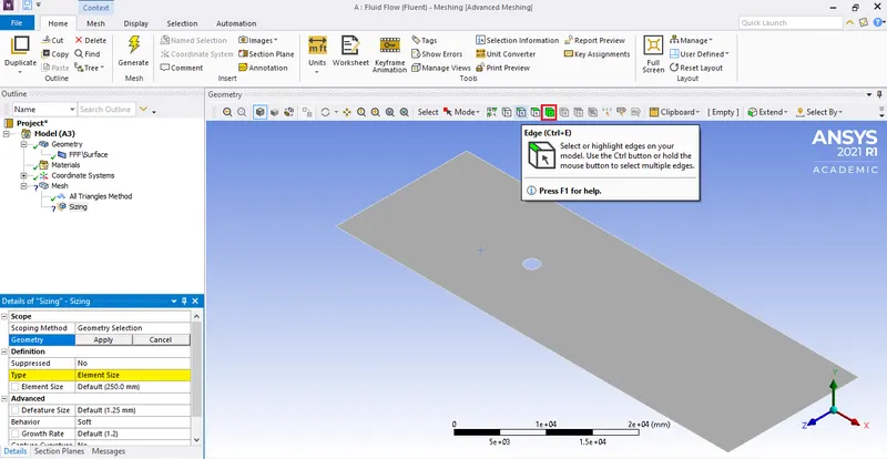
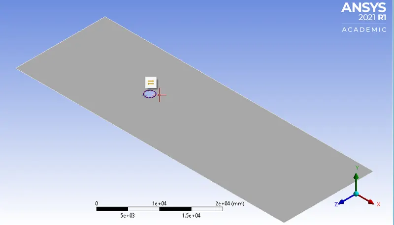
After selecting the edge, hit apply.
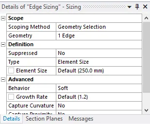
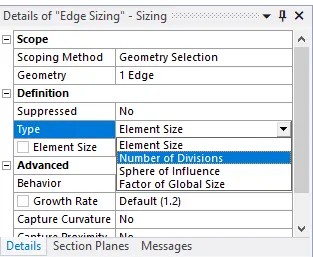
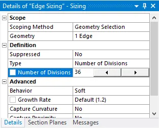
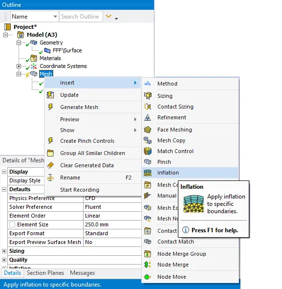
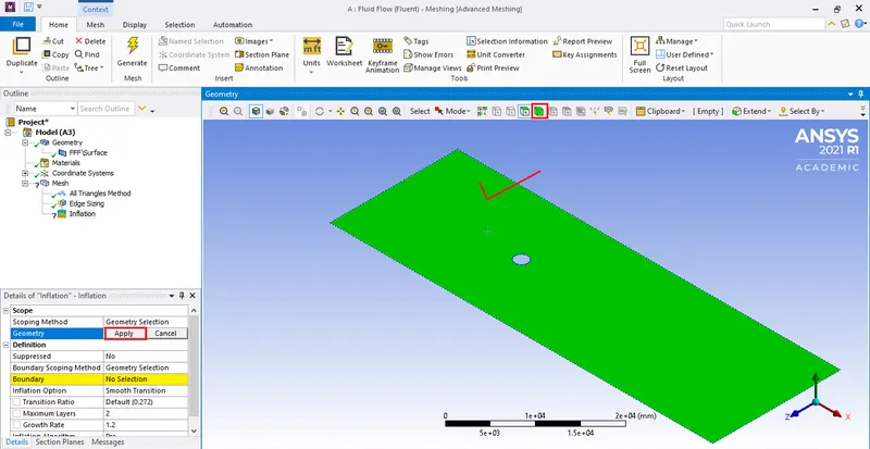
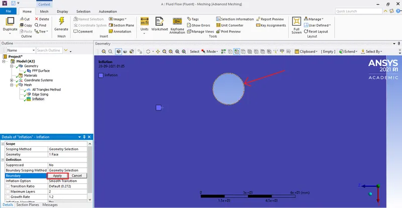
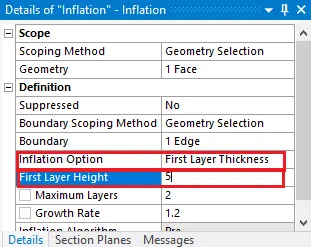
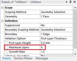
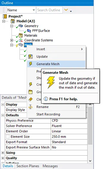
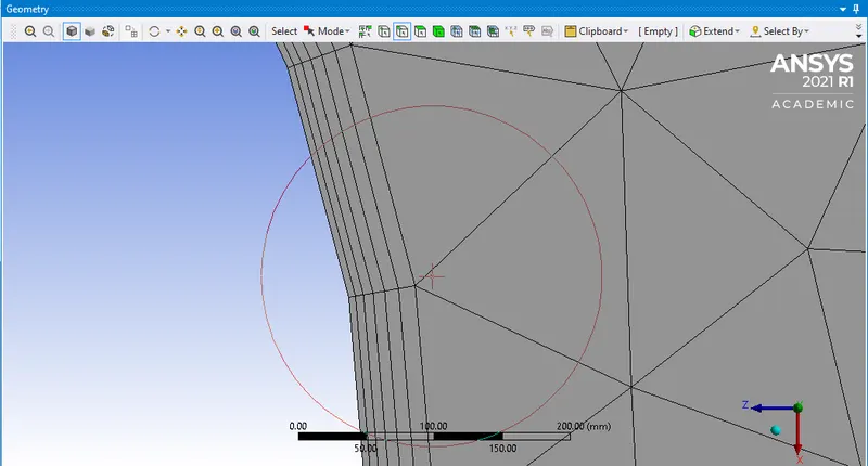
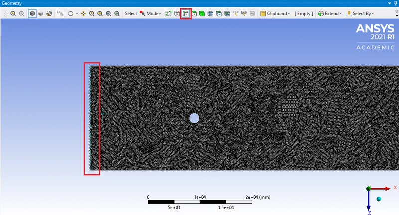
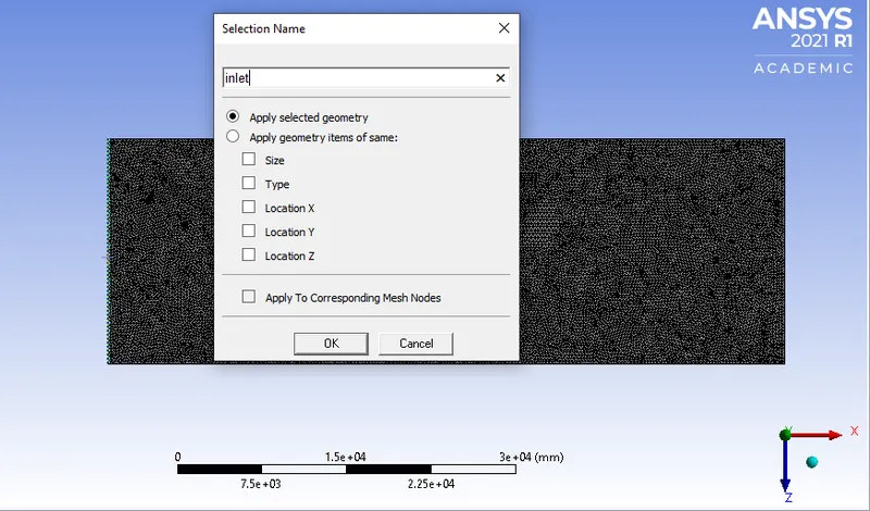
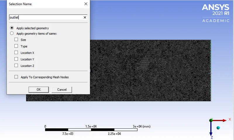
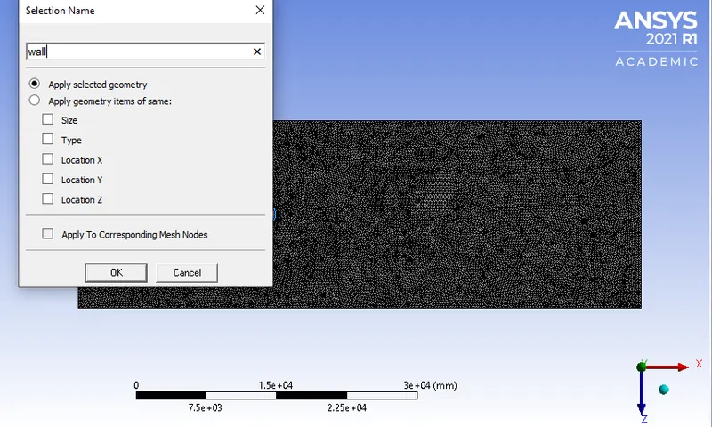
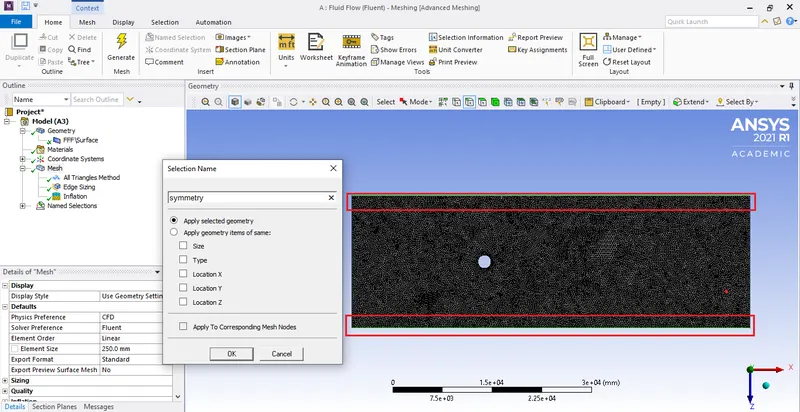
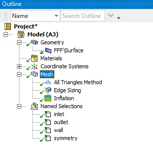
To verify the naming expand 'Named selections' under 'Outline'.
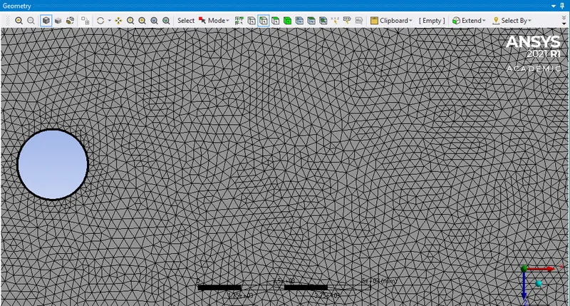
Close the mesh window and hit update.
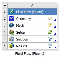
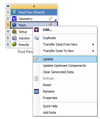
Open the setup.
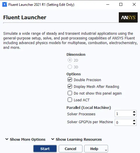
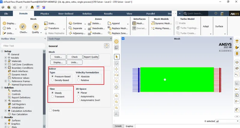
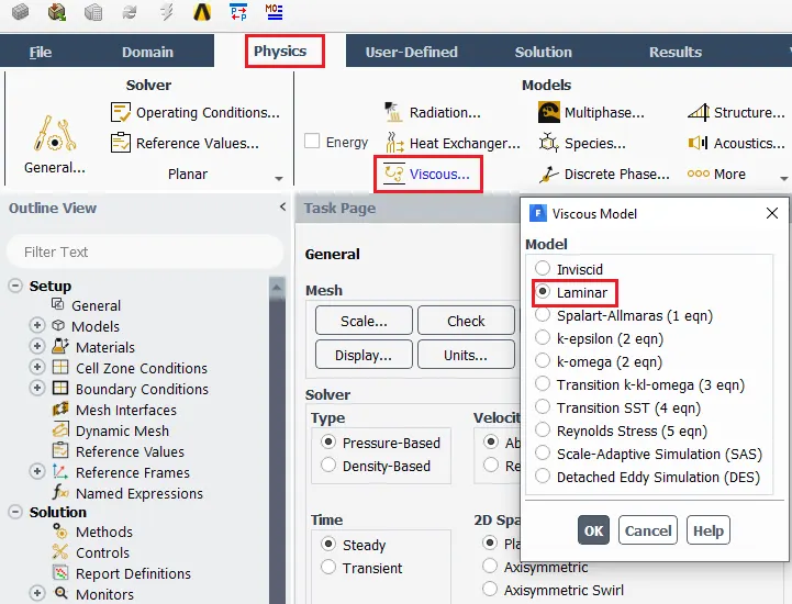
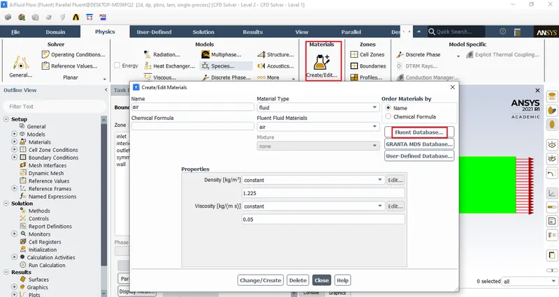
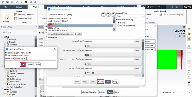
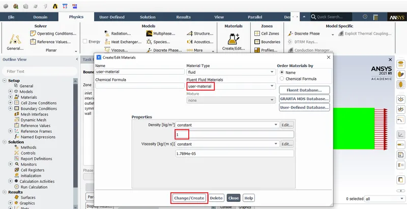
Also change viscosity to 0.05
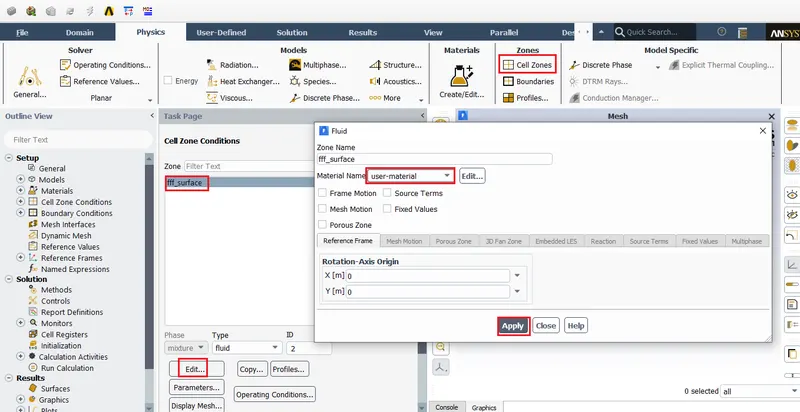
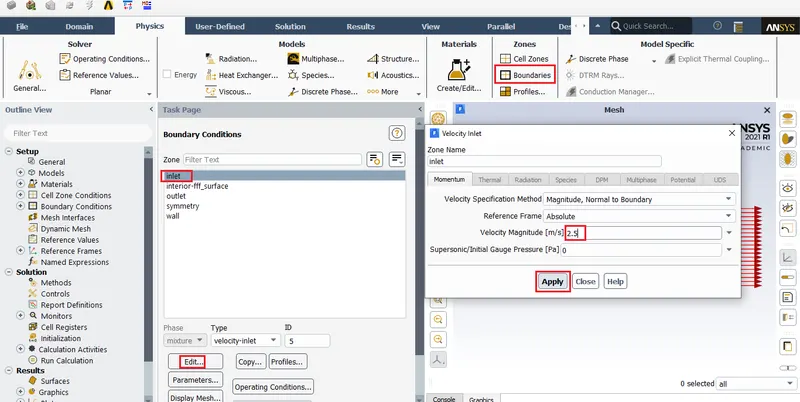
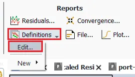
To view the type of shear condition applied to 'wall'. Hit on wall and click edit. Then we can see that ansys has assumed no slip condition for this based on the given name.
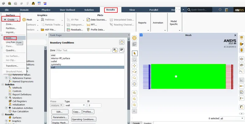
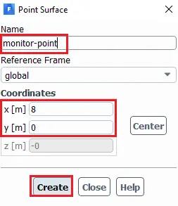
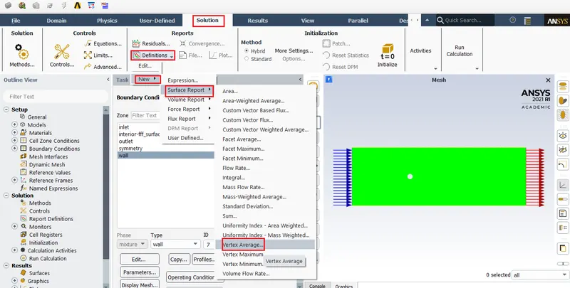
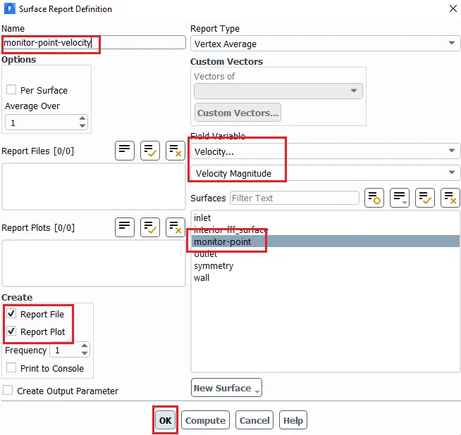
Here instead of velocity magnitude under field variable we can also use velocity X magnitude.

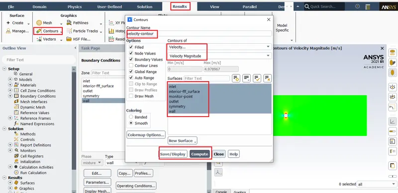
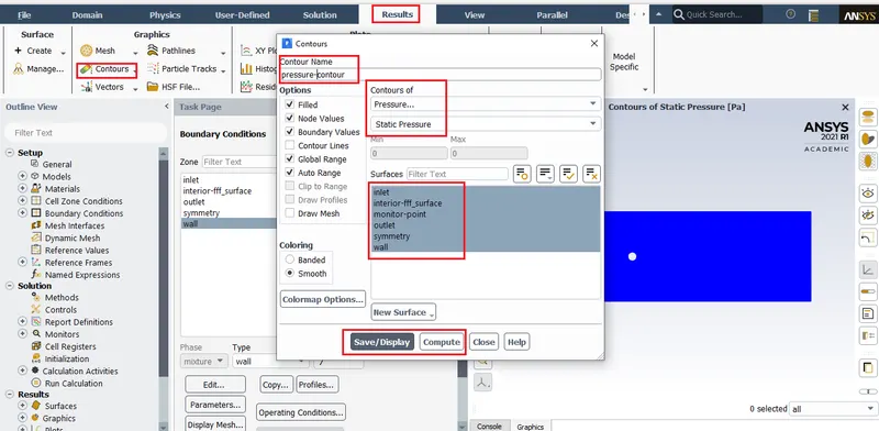
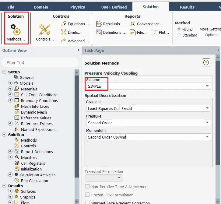
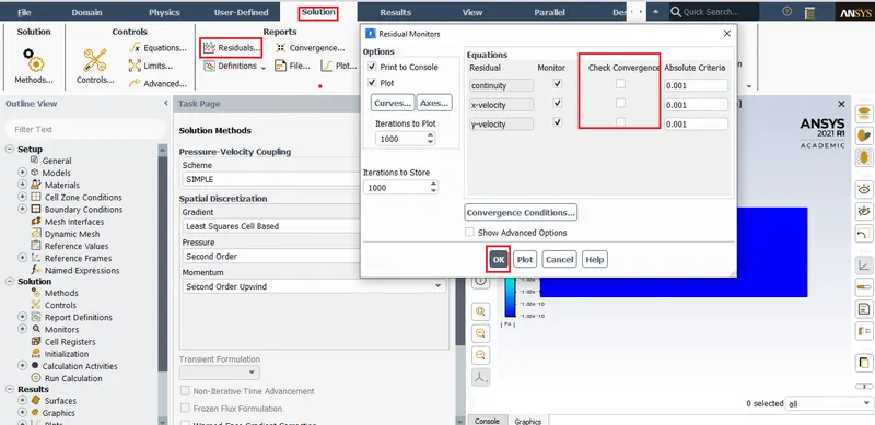
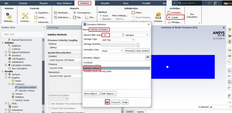
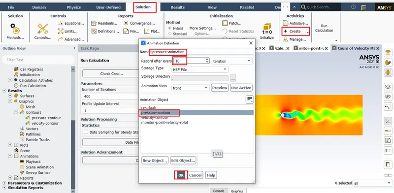
After initializing we must proceed to input the number og iterations and start calculation.
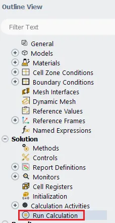
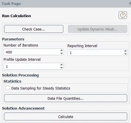
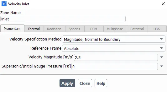
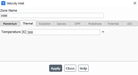
Verifying the values entered:
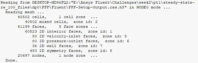
Number of cells is within the limit of 512,000.
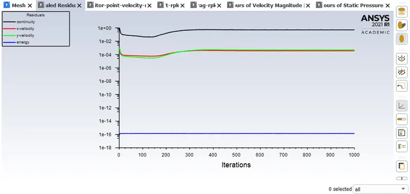
PLOTS:
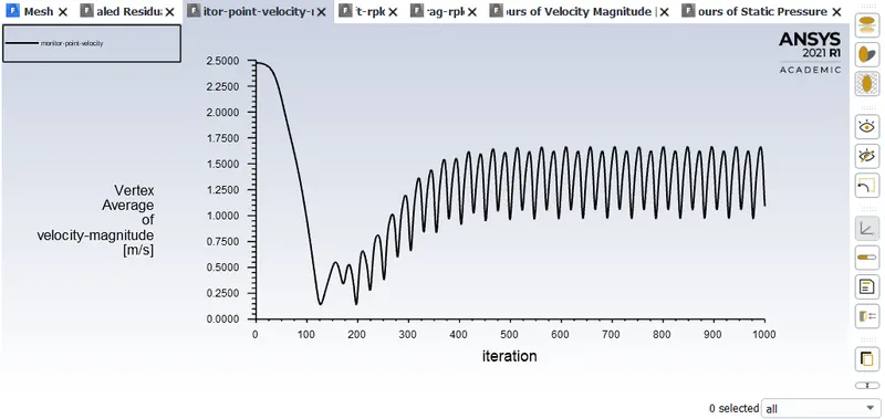
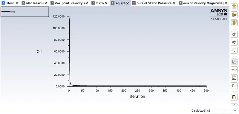
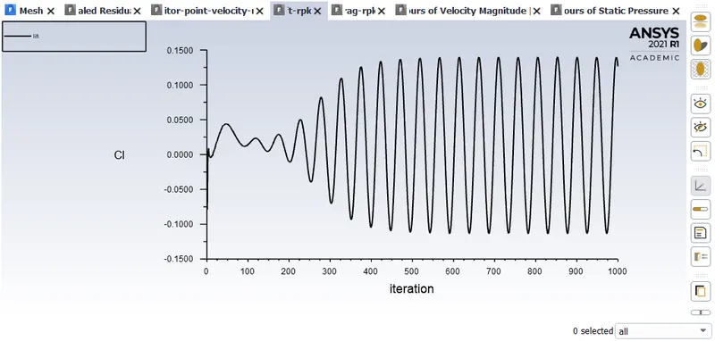
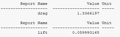
Caution: Strohaul's number shpuldn't be used for steady state simulations.
Velocity animation:
Pressure animation:
Unsteady/transient: Reynold's number 100
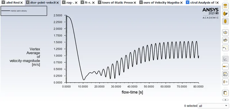
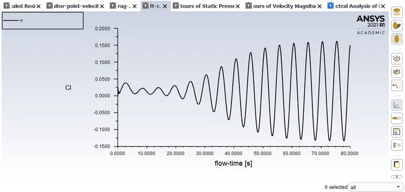
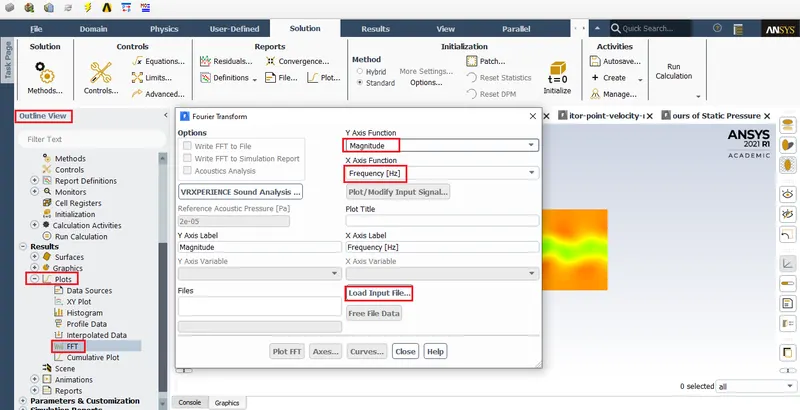
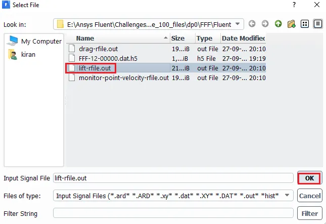
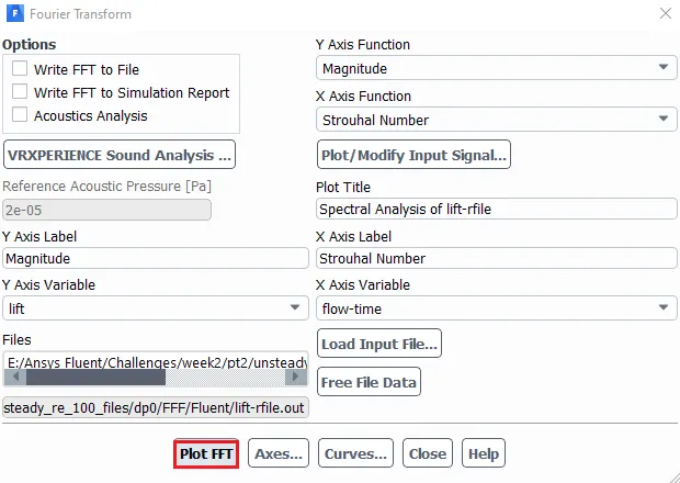
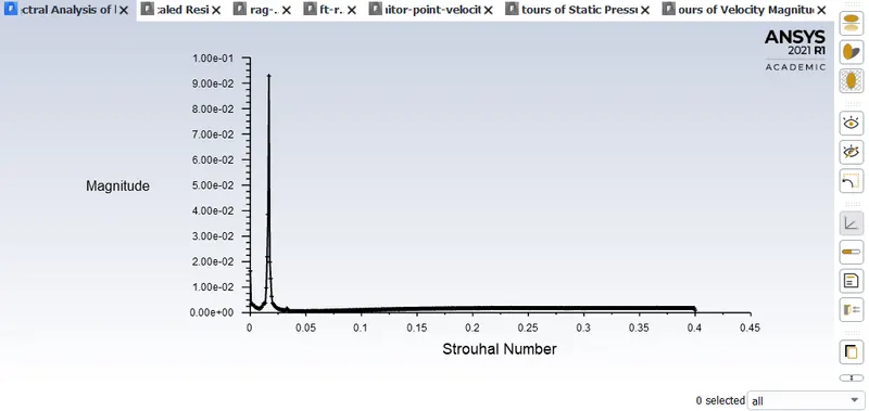
After 'Load Input File' choose the lift file and hit 'Plot FFT'.
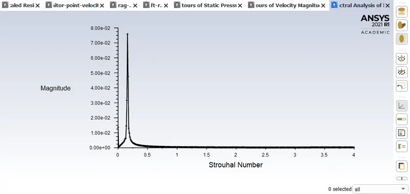
Strouhal number from coeffecient of lift: 1.6034486e-06
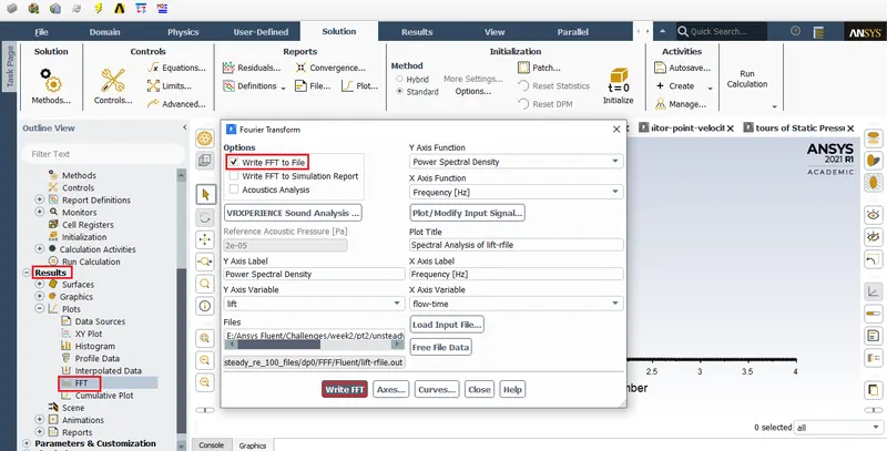
File:
https://drive.google.com/file/d/1dBLe7u5dYORK87DHfOs6CyAOmAB5KjBD/view?usp=sharing
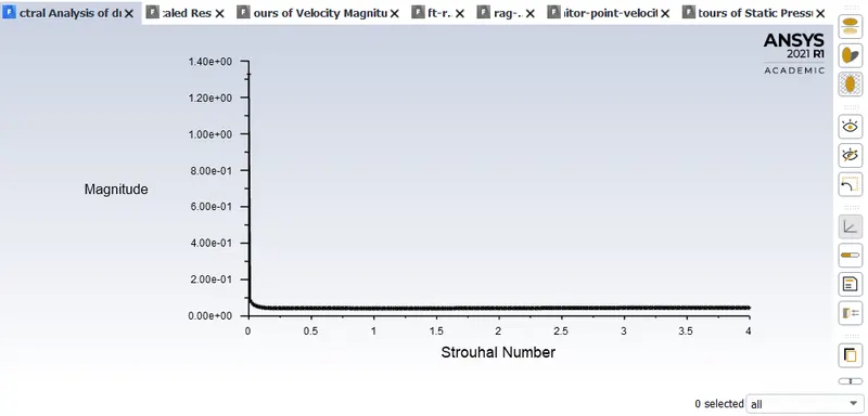
Strouhal number from coeffecient of drag: 4.5634769e-02
File:
https://drive.google.com/file/d/15rL8tGqs3xWObVLk0SNaXq919fpBQmht/view?usp=sharing
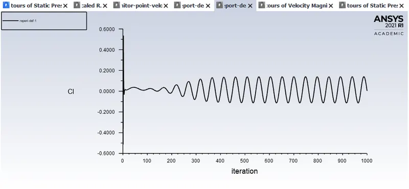
It is adviced to use coeffecient of lift to calculate Strouhal number.
Video animations
Velocity animation:
Pressure animation:
Coeffecient of lift and drag:
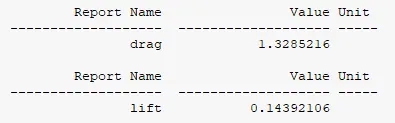
PART 2:
Reynold's number 10:
PLOTS:
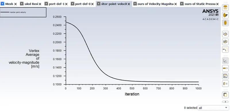
Velocity animation:
Pressure animation:
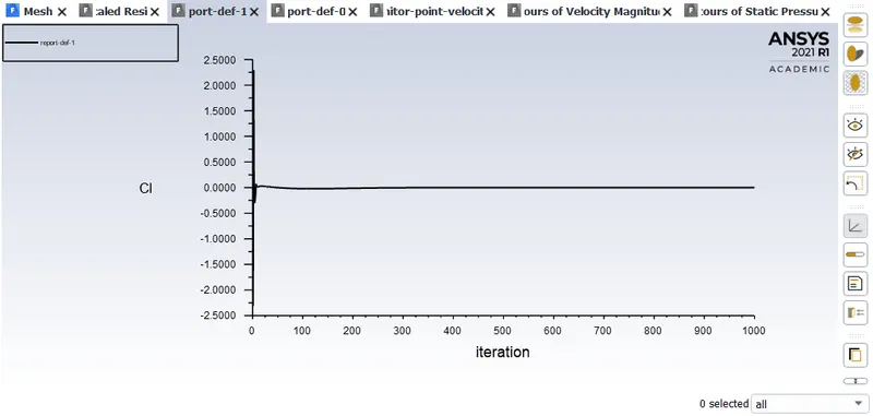
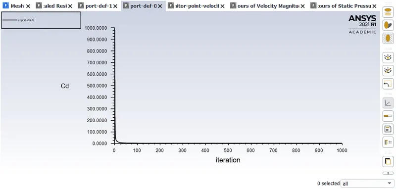
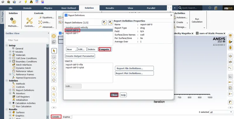
Coeffecient of lift and Coeffecient of drag
Coeffecient of drag

Coeffecient of lift

Reynold's number 100: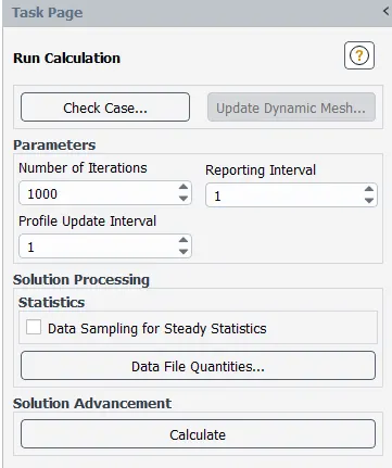
Plots:
Coeffecient of lift and drag.
Video animation:
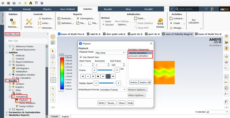
Velocity animation:
Pressure animation:
Reynold's number 1000:
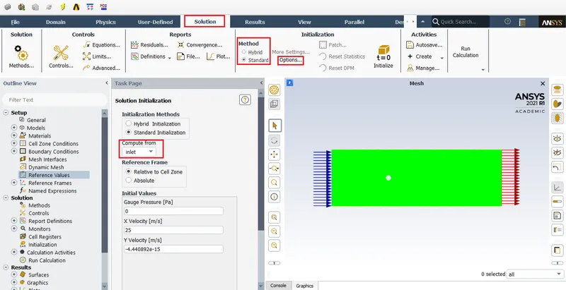
Plots:
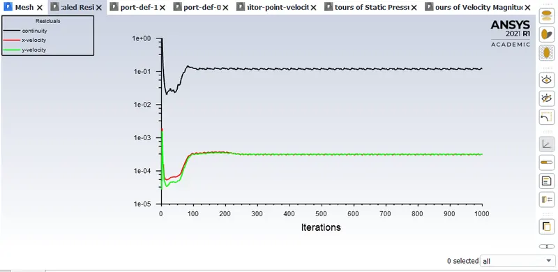
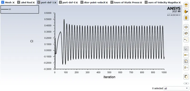
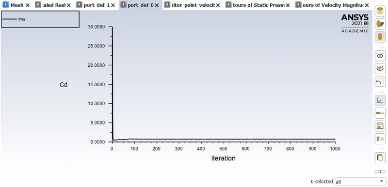
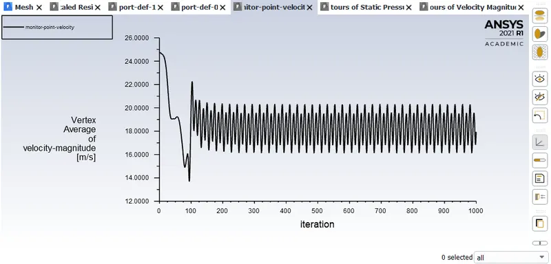
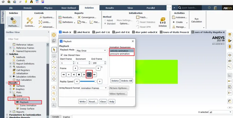
Velocity animation:
Pressure animation:
Coeffecient of lift and drag:
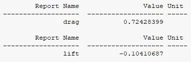
Reynold's number 10000:
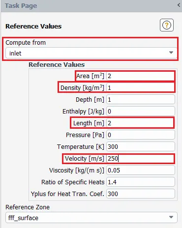
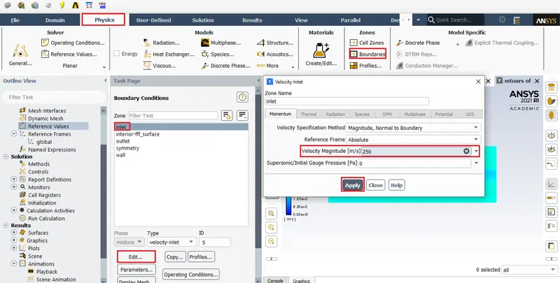
PLOTS:
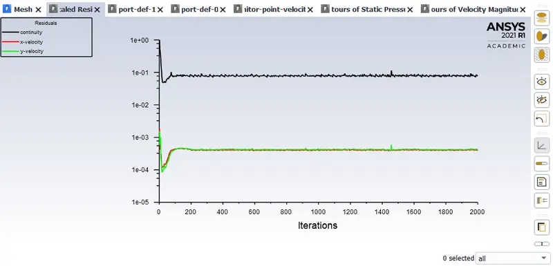
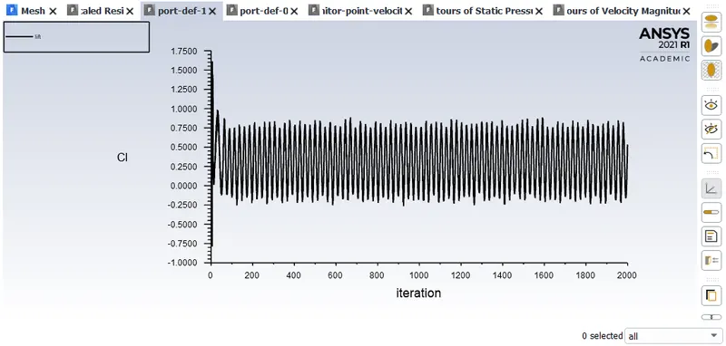
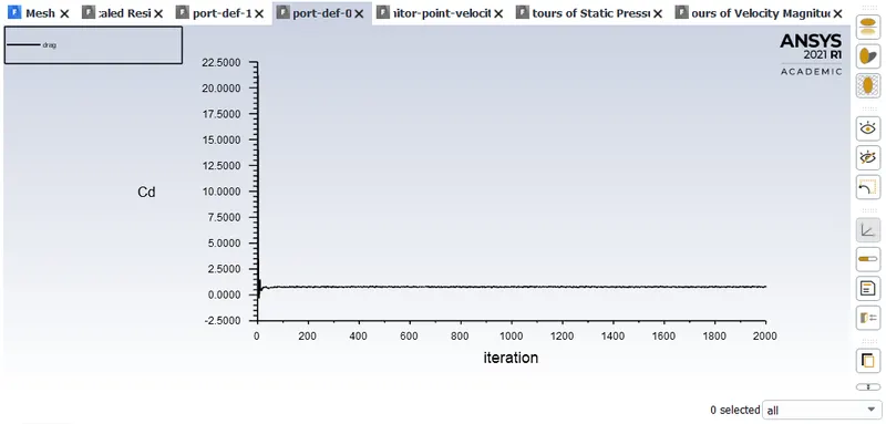
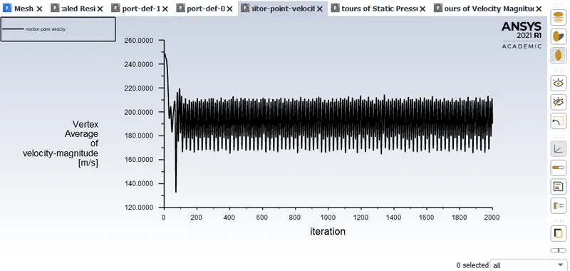
Coeffecient of lift and drag:
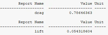
Video animation:
Velocity animation:
https://drive.google.com/file/d/1rELdIdN6uwEO9nfQaJxcEHdy6PB4HjQI/view?usp=sharing
Pressure animation:
https://drive.google.com/file/d/1knekchG-w1yX1cn6nIozH-mMOndu3_EU/view?usp=sharing
Reynold's number 100000:
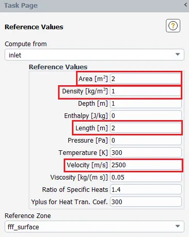
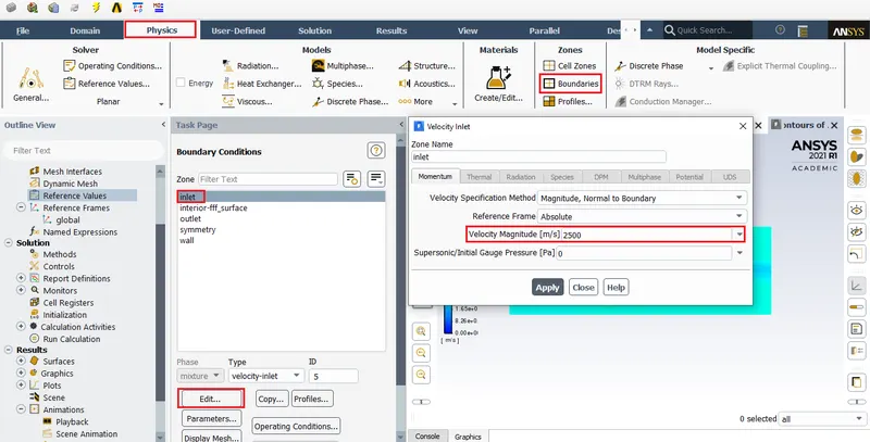
PLOTS:
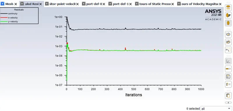
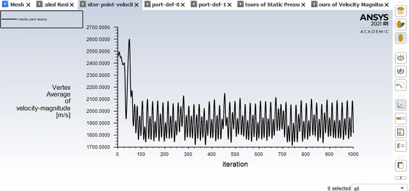
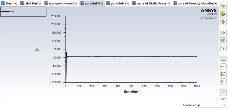
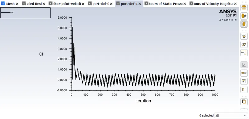
Coeffecient of lift and drag:
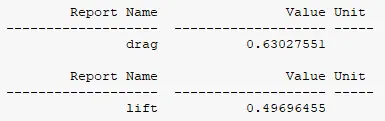
Velocity animation:
https://drive.google.com/file/d/1r7CUi28vfkr29OHP85FdE4hgOs0LbjLf/view?usp=sharing
Pressure animation:
https://drive.google.com/file/d/1LAifB1UZvGez_IOYHNNCqvXJwZDzC3MU/view?usp=sharing
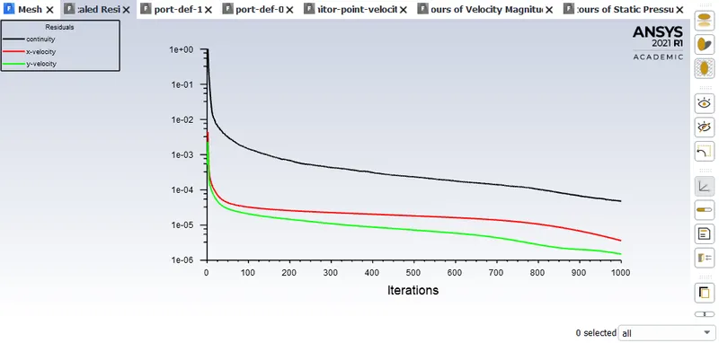
Flow convergence:
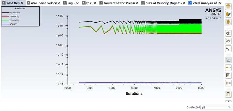
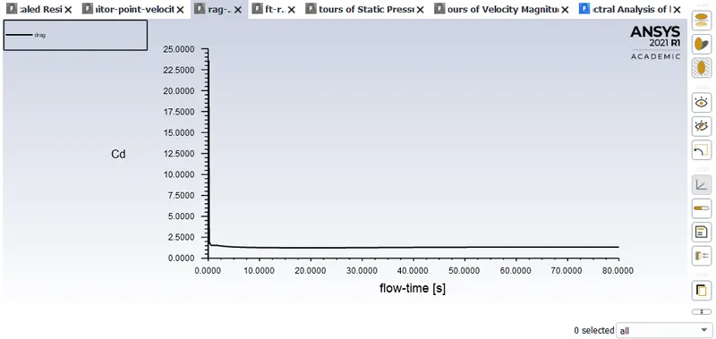
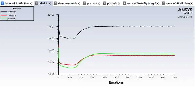
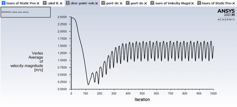
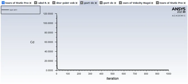
Residual plots signify whether the flow has converged or not, in addition to this we can also check the plot for coeffecient of drag, if the plot is a straight line then that means the flow solution has converged.
Results & validation:
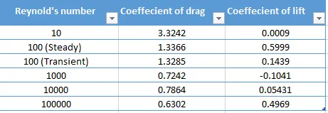
The table contains results obtained from Ansys fluent.
The effect of Reynold's number on coeffecient of drag is inversly proportional, in other words as the value of Reynold's number increases the value of coeffecient of drag decreases.
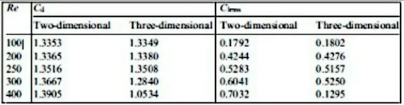
The table contains results obtained from: Numerical simulation of laminar flow past a circular cylinder - B.N. Rajani, A. Kandasamy, Sekhar Majumdar
Comparison of results obtained from this excercise will be compared with the table given above.
Two-dimensional coeffecient of drag value is considered for error calculations & from our ansys simulation we will be considering the results of steady state coeffecient of drag value at Reynold's number 100.
Error percentage for coeffecient of drag at Reynold's number 100 is given below,
`[(1.3366-1.3353)/1.3366]*100=0.097%`
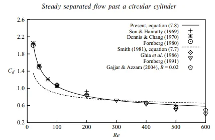
The graph contains results obtained from: Steady separated flow past a circular cylinder at low Reynolds numbers - SUBHANKAR SEN, SANJAY MITTAL AND GAUTAM BISWAS
Two-dimensional coeffecient of drag value is considered for error calculations & from our ansys simulation we will be considering the results of steady state coeffecient of drag value at Reynold's number 100.
Error percentage for coeffecient of drag at Reynold's number 100 is given below,
`[(1.3366-1.1)/1.3366]*100=17.70%`
REFERENCES:
Von karman street:
https://aerospaceengineeringblog.com/the-von-karman-vortex-street-and-tacoma-narrows-disaster/
Reynold's number:
https://www.simscale.com/docs/simwiki/numerics-background/what-is-the-reynolds-number/
Ansys pressure based solver description & much more:
https://drive.google.com/file/d/19HLw6jCbhMxJu834UcvUac_Shphz1mmZ/view?usp=sharing
Research papers:
https://drive.google.com/file/d/1yfjsc7yatWIilKuOo5pjAWuMvmxYG8yZ/view?usp=sharing
https://drive.google.com/file/d/1DmpqKNbstGBj-1-RZ57ryQuN5FExlVY2/view?usp=sharing
https://drive.google.com/file/d/14Scn174ELiGpkLR3Ax6ALePJ4GX5wJpF/view?usp=sharing
https://drive.google.com/file/d/14Scn174ELiGpkLR3Ax6ALePJ4GX5wJpF/view?usp=sharing
https://drive.google.com/file/d/14ufV1E3P4RHKmscgkD7T-HpXU_EZlhkm/view?usp=sharing
https://drive.google.com/file/d/1X6Ey3wES7kCNvDIr7n3CC86eNJJg0BMl/view?usp=sharing