Week 2 Challenge : Surface meshing on a Pressure valve
Surface meshing on a Pressure valve
Aim:
The aim of this study is to access the impact of different target lengths on mesh quality for a model with geomentrical errors. The objective is to determine which target length results in the best mesh quality.
Introduction:
- <!-- [if !supportLists]--> A structured mesh forms the foundation for accurate analysis amd valuable insights. In this comprehensive report, we embark on an investigation of meshing methodologies and their impact on the analysis of a specific model, a pressure valve.
- <!-- [if !supportLists]--> The pressure valve, a component in various industrial applications, plays a pivotal role in controlling fluid flows and maintaining system safety. Accurate simulation of its mechanical behavior is essential for design optimization and performance assessment. This report focuses on a multi-faceted approach:
<!-- [if !supportLists]--> 1. <!--[endif]-->Geomentric Error Correction
- <!-- [if !supportLists]--> <!--[endif]-->Before engaging in the meshing process, a diligent examination of the model’s geomentry is conducted. Geomentric errors such as gaps, overlaps, self-intersections, or other anomalies can compromise the reliability of subsequent analysis. These issues are addressed through topology cleanup, ensuring that the model is free from any geomentric descrepancies.
<!-- [if !supportLists]--> 2. <!--[endif]-->Meshing with Differing Target Lengths:
- <!-- [if !supportLists]--> To explore the effects of mesh on analysis outcomes, we investigate three distinct cases, each employing a different target length: 1mm, 3mm, & 5mm. Each target length is applied to the entire model individually, resulting in three separate meshed models. The choice of target length is as it shapes the trade-off between computational accuracy and efficiency.
<!-- [if !supportLists]--> 3. <!--[endif]-->Element Selection and Quality Control:
- <!-- [if !supportLists]--> <!--[endif]-->In case, triangular (Tria) elements are utilized for meshing. These elements offer a balanced approach between accuracy and computational resources. To evaluate the mesh quality by examining aspects ratio, skewness, and element distribution, ensuring that the mesh is well-structured and suitable for analysis.
<!-- [if !supportLists]--> 4. <!--[endif]-->Comparative Analysis:
- <!-- [if !supportLists]--> This report concludes with a comprehensive evaluation of the meshing results from all three cases. By constracting and analyzing the outcomes, we endeavour to identify which target length yields the most accurate and reliable results for the pressure valve model.
Procedure:
Surface meshing a pressure valve is a critical step in finite element analysis (FEA) to ensure that the accurate results. For solving we follow the bellow procedure,
<!-- [if !supportLists]--> 1. <!--[endif]-->Import CAD Geomentry:
<!-- [if !supportLists]--> · <!--[endif]-->Import or create a 3D CAD model of the pressure valve.
<!-- [if !supportLists]--> · <!--[endif]-->Ensure the CAD model is well-defined, with all relevant components.
<!-- [if !supportLists]--> · <!--[endif]-->File à Open à browse the location of the CAD model à Click open
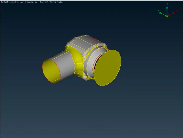
<!-- [if !supportLists]--> · <!--[endif]-->Here it shows the geomentry has been uploaded.
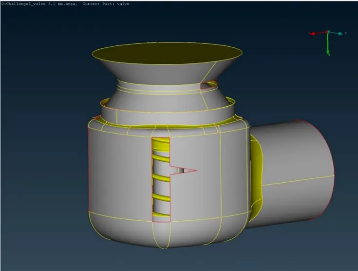
<!-- [if !supportLists]--> · <!--[endif]-->We can see the lot of topological errors, but before the topo clean up we need to check the geomentry check to see all the errors of the model.
<!-- [if !supportLists]--> 1. <!--[endif]-->Geomentry Check-up:
<!-- [if !supportLists]--> · <!--[endif]-->Inspect the CAD model for geomentric errors, such as gaps, overlaps, or small features that could hinder mesh generation. Use the CAD tools to address and correct the errors.
<!-- [if !supportLists]--> · <!--[endif]-->Geomentry check-ups is done to check whether there are any errors in the model like Unclosed faces, Super imposing faces, any holes or any geomentry disorder.
To check this, Toolbar à Checks à Geomentry à Visible à Execute.
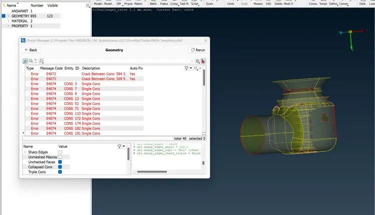
- <!-- [if !supportLists]--> In the above image, you can see a lot of errors is visible in the wireframe model after the geomentry check up. These are the errors that needs to be solved. Those errors if you see there are lot of single cons that share edge with only one surface, as this is 3D geomentry for CFD applications we need closed surfaces to do volumetric mesh and we need to fix single cons.
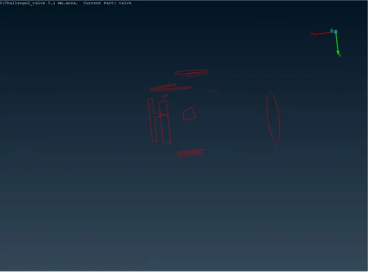
- <!-- [if !supportLists]--> <!--[endif]-->This image shows the wireframe mode of the model with the single cons visible.
- <!-- [if !supportLists]--> <!--[endif]-->Now need to clear all the topo errors and we expect the double cons, never consider them as a error.
<!-- [if !supportLists]--> 1. <!--[endif]-->Geomentry Cleanup:
- <!-- [if !supportLists]--> <!--[endif]-->If you want to see the location of error in the geomentry check-up, you can select pick and select the con to see where it is present and see the preview of the error (single con) in the model.
- <!-- [if !supportLists]--> <!--[endif]-->We use the visibility tools to see the single cons and we have to clear the single cons wherever they present.
<!-- [if !supportLists]--> · <!--[endif]-->We will patch all the single cons by creating a new face.
<!-- [if !supportLists]--> · <!--[endif]-->Patch the surfaces by using the new under faces.
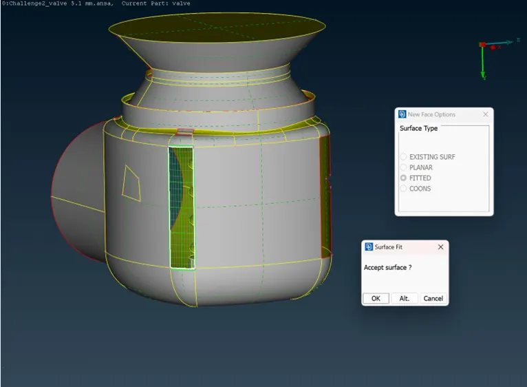
- <!-- [if !supportLists]--> Here we have 4 options to use, they are Existing surface, Planar, Fitted, and Coons.
- <!-- [if !supportLists]--> <!--[endif]-->We can use the different type of algorithms to create face depending upon the applications, so when one fails to create a better surface, we try with other alternate.
- <!-- [if !supportLists]--> In the image you can see the preview of the face creating by using Fitted surface.
Topo Faces à New Face options à Fitted surface selected
And try with alternate and click on “Ok”.
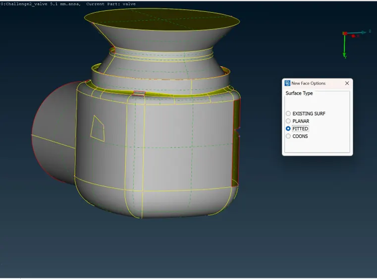
<!-- [if !supportLists]--> · <!--[endif]-->Here the surfaces have been patched and created.
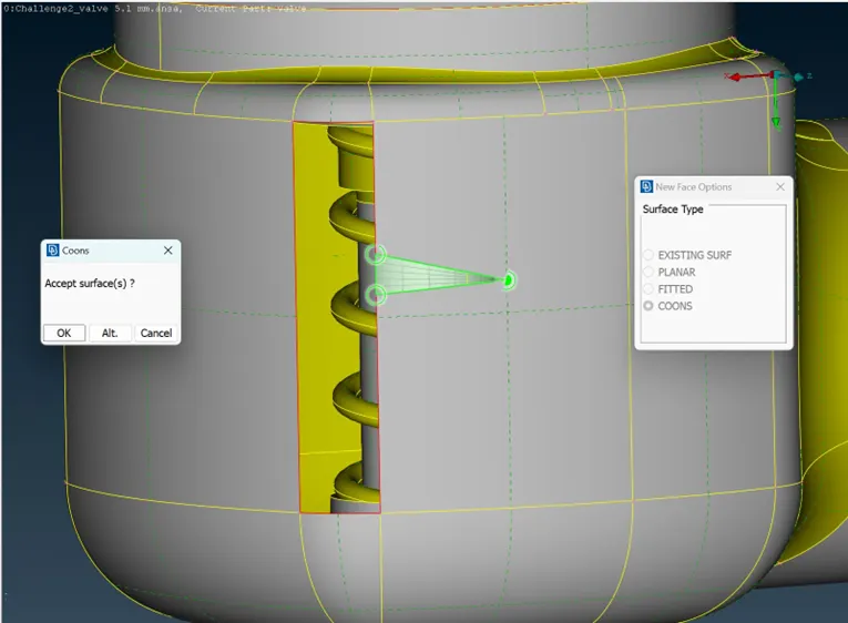
<!-- [if !supportLists]--> · <!--[endif]-->Here the surfaces are been patched by using Coons.
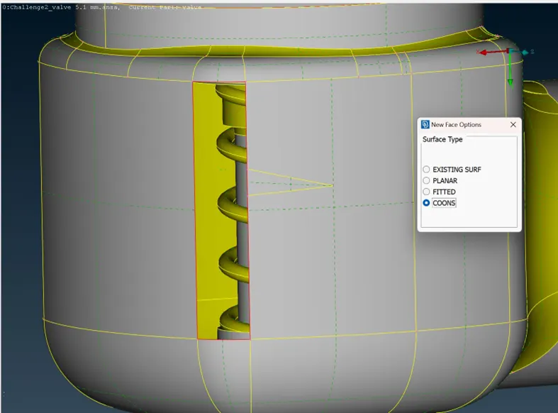
<!-- [if !supportLists]--> · <!--[endif]-->In the similar way that we create the surface wherever there are single cons by using the algorithms.
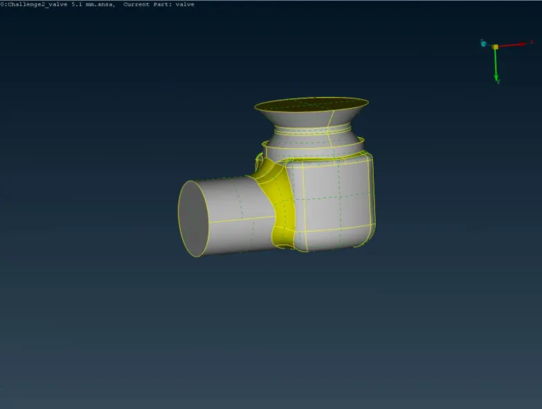
<!-- [if !supportLists]--> · <!--[endif]-->The above image is the fully patched surfaces.
<!-- [if !supportLists]--> · <!--[endif]-->After all the patches let us do the geomentry check again, to see whether any error exist or not.
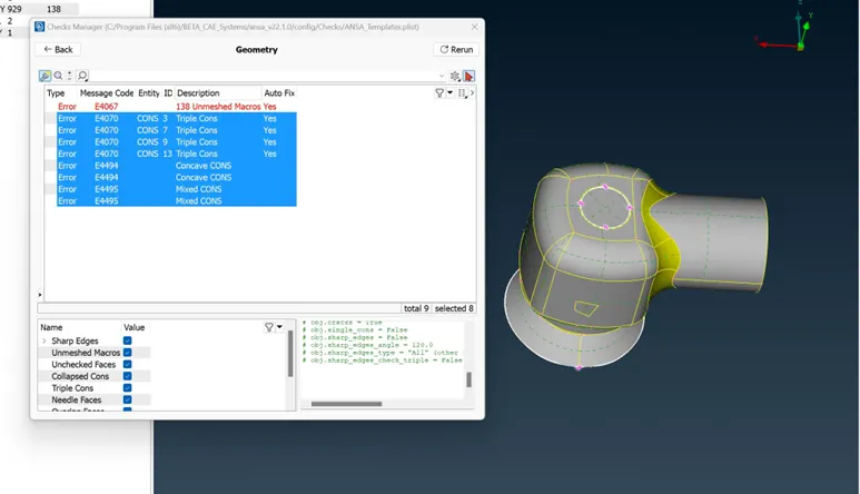
- <!-- [if !supportLists]--> In here we can observe there are no single cons errors, but you have triple cons exists at the bottom of the geomentry as we have closed the bottom with a surface. Triple cons is not an error, it’s just an warning.
- <!-- [if !supportLists]--> <!--[endif]-->Here in our cases the surfaces are important, so there will be formation of triple con and we will ignore this triple con as all surfaces are important.
- <!-- [if !supportLists]--> <!--[endif]-->To assign PID’s before that ensure that there are small surfaces have been cleared, because while meshing they may will interfere the smaller surfaces like the mesh element may not fit in the smaller surfaces.
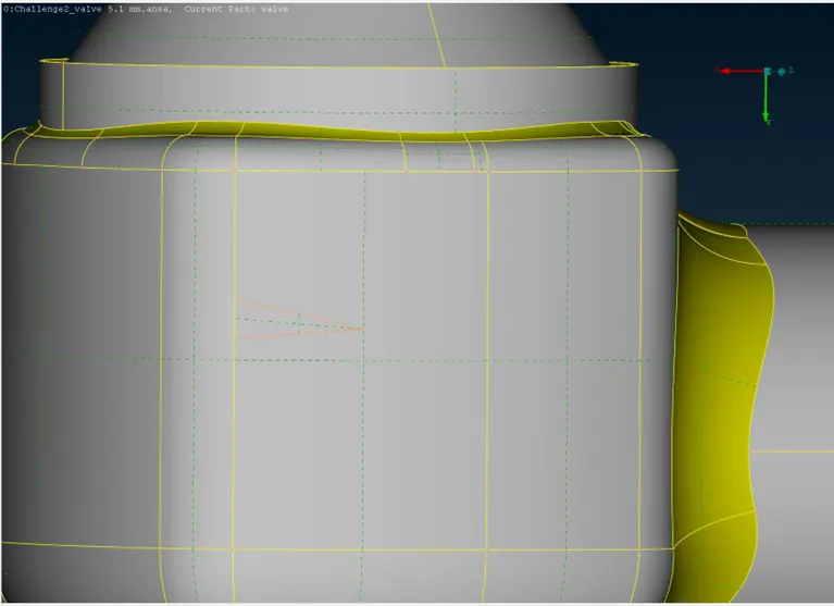
<!-- [if !supportLists]--> · <!--[endif]-->The above image shows the smaller surfaces are been cleared by using Cut tool.
Topo : Faces à Cut à Select the unwanted surface to be cleared and middle click.
<!-- [if !supportLists]--> 1. <!--[endif]-->Setting/Creating up relevant PID’s:
- <!-- [if !supportLists]--> <!--[endif]-->We need to specify the names between the different boundary conditions for the various parts and we need to activate the cross hatches before setting-up PID’s.
- <!-- [if !supportLists]--> In the top we can see the option called properties manager, there will be only one default PID. In order to create the new PID, right click on the properties manager à click new à PShell à PShell. Then the give name for the various parts in the popup box à Click ok.
- <!-- [if !supportLists]--> In the similar way to create the PID for Inlet, Outlet, Spring, Valve head, Body, Column, Base, Surface.
Created PID’s
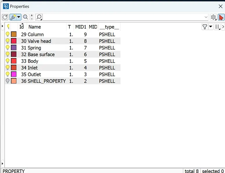
<!-- [if !supportLists]--> · <!--[endif]-->Here shows the PID’s have been created and named for various parts.
Inlet
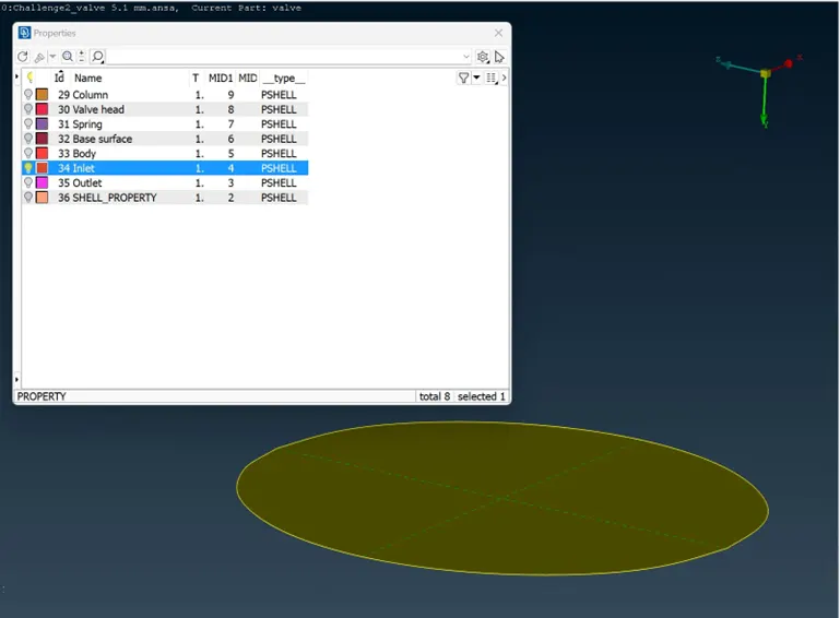
<!-- [if !supportLists]--> · <!--[endif]-->This shows that the Inlet of the body is only visible.
Outlet
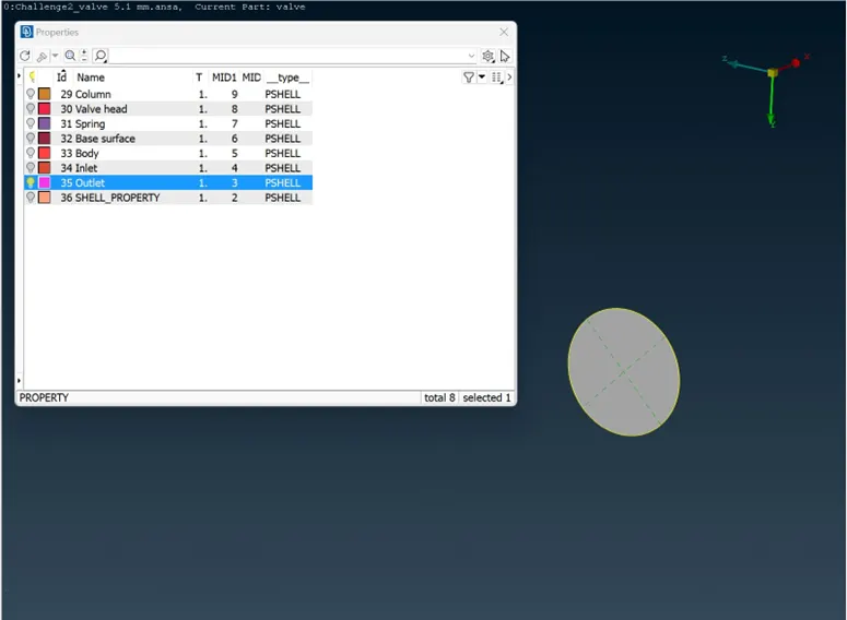
<!-- [if !supportLists]--> · <!--[endif]-->This image shows the Outlet of the body is only visible.
Body
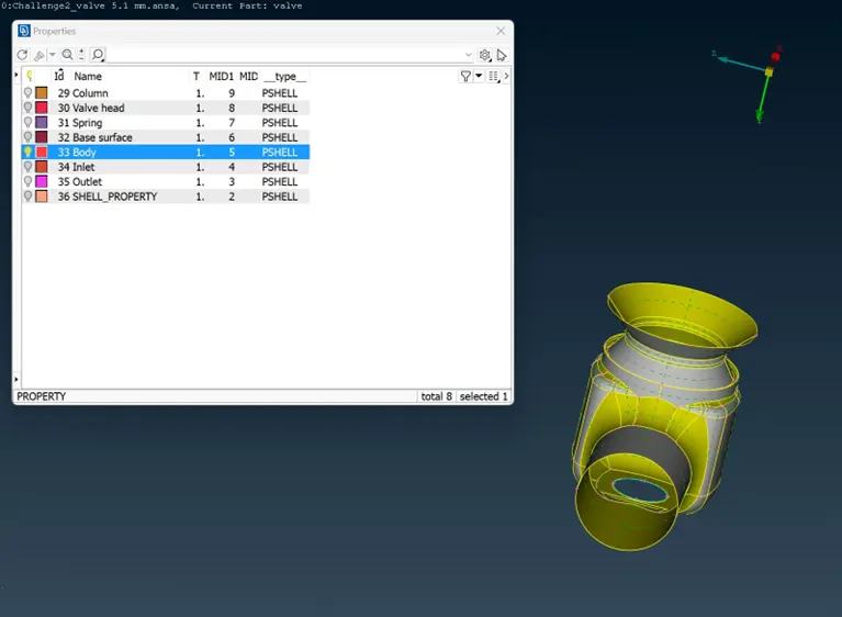
<!-- [if !supportLists]--> · <!--[endif]-->This image shows the Body is only visible.
Base Surface
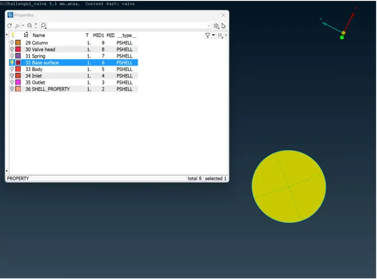
<!-- [if !supportLists]--> · <!--[endif]-->This image shows the bottom of the Base Surface is only visible.
Spring
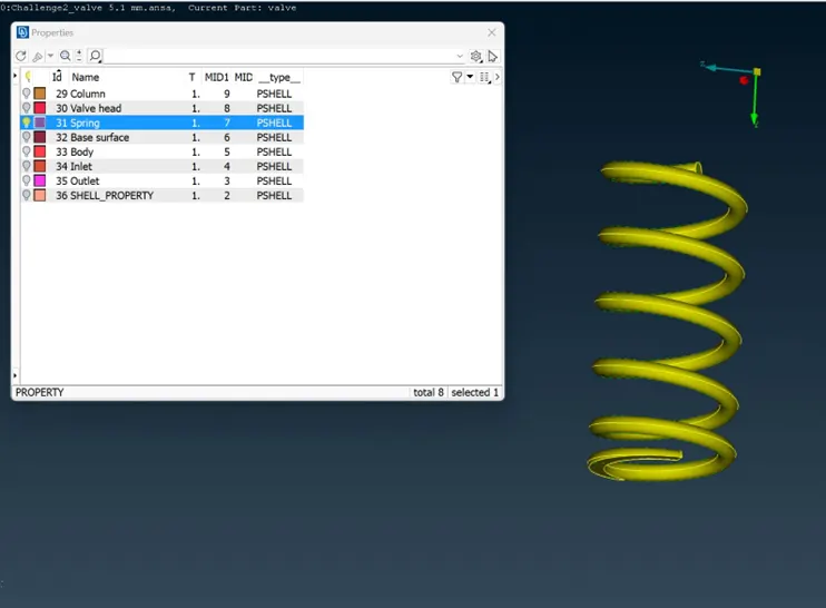
<!-- [if !supportLists]--> · <!--[endif]-->This image shows that the Spring is only visible.
Valve Head
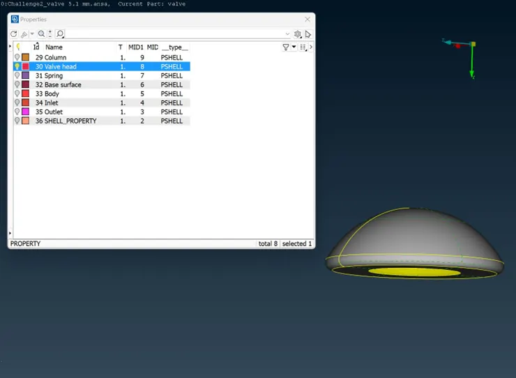
<!-- [if !supportLists]--> · <!--[endif]-->This image shows that the Valve Head is only visible.
Column
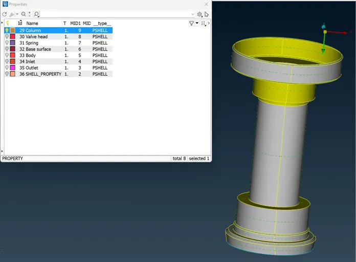
<!-- [if !supportLists]--> · <!--[endif]-->This image shows that the Column has been only visible.
<!-- [if !supportLists]--> · <!--[endif]-->After creating all the PID’s and naming them, now they are ready for meshing.
<!-- [if !supportLists]--> 1. <!--[endif]-->Setting up the Element size or Length:
- <!-- [if !supportLists]--> There are different target lengths as of three different cases we have to mesh the model with the different lengths as given.
<!-- [if !supportLists]--> · <!--[endif]-->The Target length are = 1mm, 3mm, and 5mm.
<!-- [if !supportLists]--> · <!--[endif]--> Run the mesh with the different cases and compare the results as follows.
Case 1
Target Length = 1mm.
<!-- [if !supportLists]--> · <!--[endif]--> We have give the mesh length of four places.
<!-- [if !supportLists]--> · <!--[endif]-->1) The Perimeters of the mesh length is selected as 1mm.
2) The Macros of the mesh length is selected as 1mm.
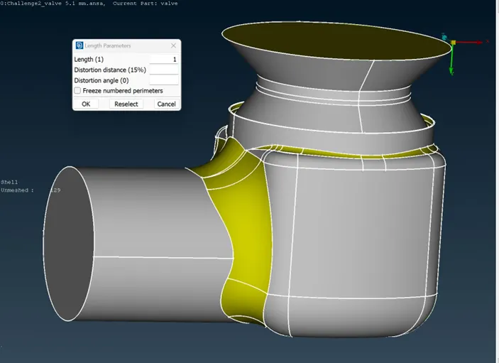
Select Mesh à Click on Lengths à Now select perimeters à now drag and select the entire model by using box selection tool à click on the middle mouse button à the Length parameters will pop-up, now select the element length as 1mm à click on middle mouse button.
- <!-- [if !supportLists]--> By the similar way to select macros instead of perimeters under the length and give the mesh length as 1mm.
Perimeters for Body
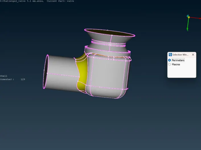
- <!-- [if !supportLists]--> The below image shows the length of the mesh are selected as 1mm for Perimeters.
Macros for Body
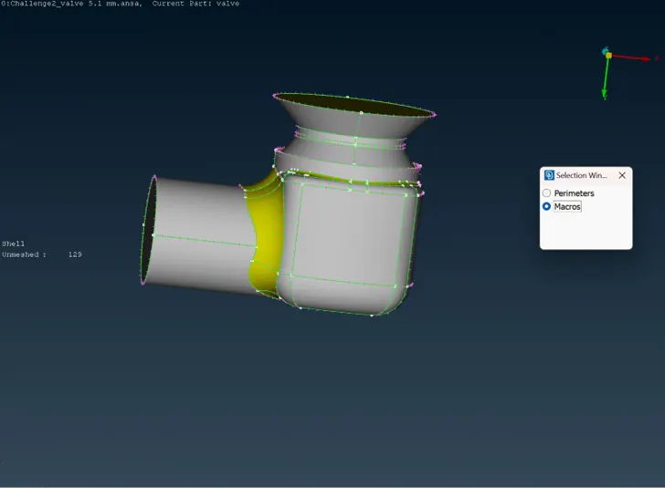
<!-- [if !supportLists]--> · <!--[endif]-->The below image shows that the mesh length has selected as 1mm for Macros.
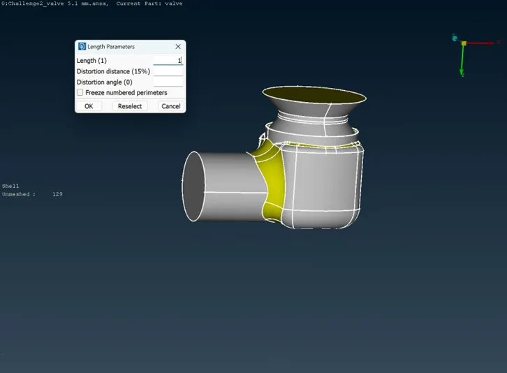
<!-- [if !supportLists]--> · <!--[endif]-->Then you can see the geomentry after giving the mesh length for the body in the below image.
External Surface
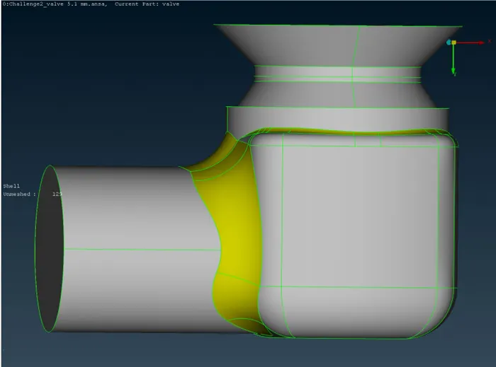
Internal Surface
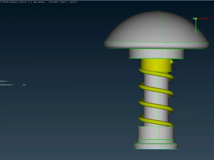
<!-- [if !supportLists]--> · <!--[endif]-->By selecting the various parts inside the body, the mesh length has been selected 1mm for each part to see the result.
Mesh Parameters
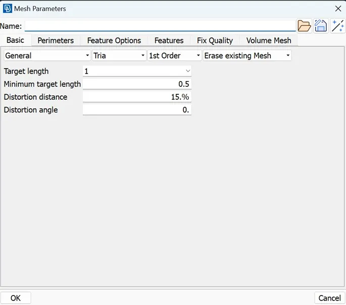
<!-- [if !supportLists]-->· <!--[endif]-->3) The target length is set up 1mm, and minimum target length is 0.5 and the mesh type is selected as Tria in the Mesh parameters.
Quality Criteria
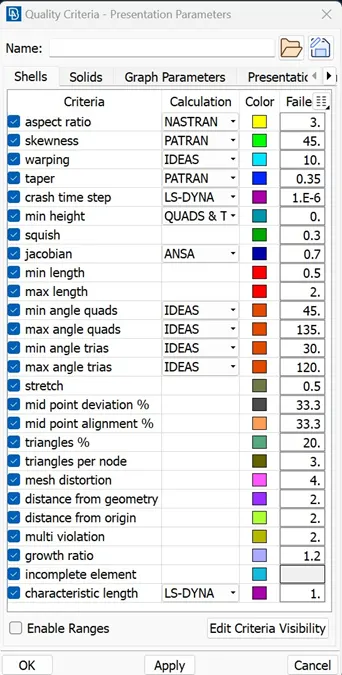
· 4) Give the minimum and maximum length as 0.5mm and 2mm respectively and keep remaining the default
<!-- [if !supportLists]--> · <!--[endif]-->After the selecting the length target in the mesh parameters and quality of the mesh, next we need to mesh the module.
<!-- [if !supportLists]--> 1. <!--[endif]-->Selecting and Generating the Mesh Type
Here we will select the Meshing algorithms by following these steps,
Go to Mesh Generation à Spot Mesh à Drag and select the entire model by using box selection tool à Now after selecting the model click on to the scroll button/middle button on mouse to mesh (or) we can select directly cisible under drop down menu of spot mesh.
<!-- [if !supportLists]--> · <!--[endif]-->The image shows that the model after the generation of mesh in below.
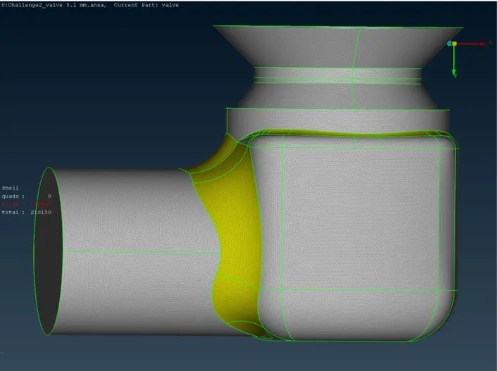
Body Mesh
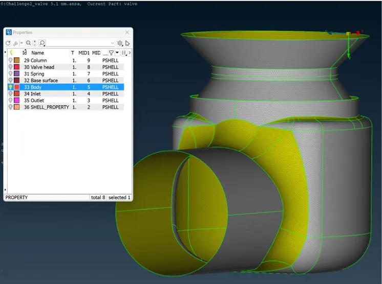
<!-- [if !supportLists]--> · <!--[endif]-->In this image shows the mesh length of the Body is 1mm.
Spring Mesh
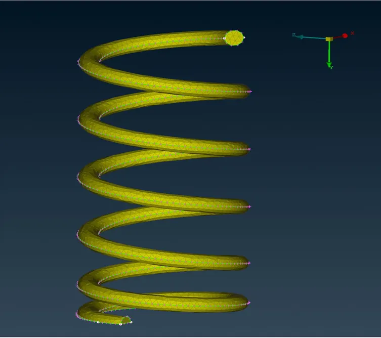
<!-- [if !supportLists]--> · <!--[endif]-->This image shows that the meshed surface of the Spring is 1mm.
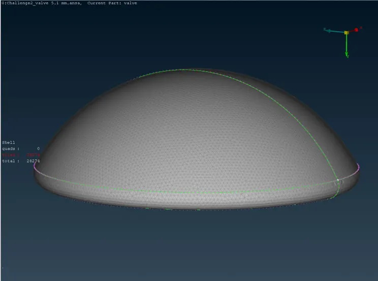
Valve Head Mesh
Column Mesh
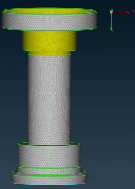
<!-- [if !supportLists]-->· <!--[endif]-->This image shows that the meshed surface of the Column in 1mm.
Case 2
Target Length = 3mm
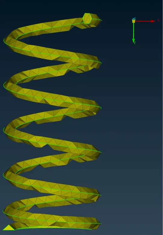
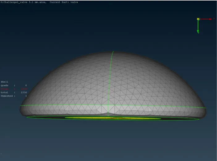
<!-- [if !supportLists]--> · <!--[endif]-->Everything same as above case but the only thing needed to be change is the target length of the mesh is 3mm.
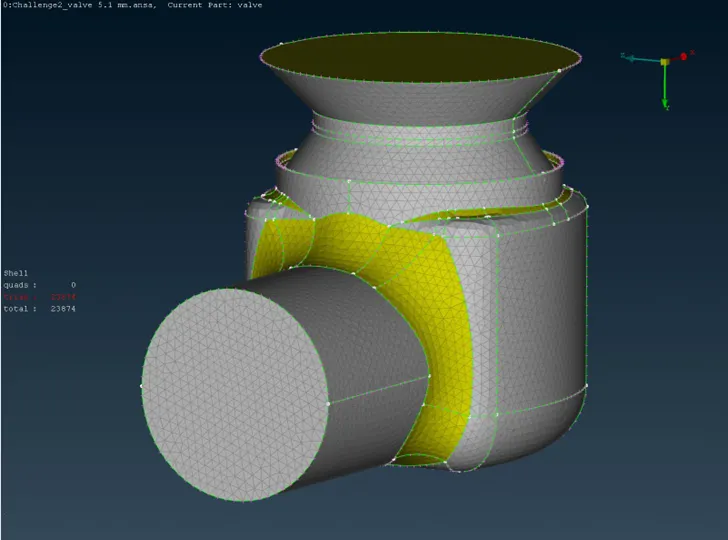
Body Mesh
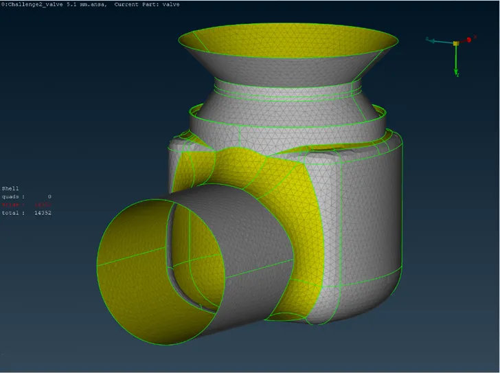
<!-- [if !supportLists]--> · <!--[endif]-->Then you can see the geomentry after giving the mesh length in the above image.
Spring Mesh
Valve Head Mesh
Column Mesh
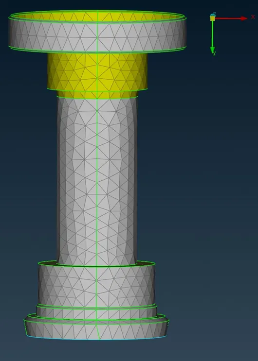
<!-- [if !supportLists]--> · <!--[endif]-->These images shows that the final view of the inside parts of the model after the mesh generation.
Case 3
Target Length = 5mm
<!-- [if !supportLists]--> · <!--[endif]-->Everything same as above case but the only thing needed to be change is the target length of the mesh is 3mm.
<!-- [if !supportLists]--> · <!--[endif]-->Then you can see the geomentry after giving the mesh length of 5mm.
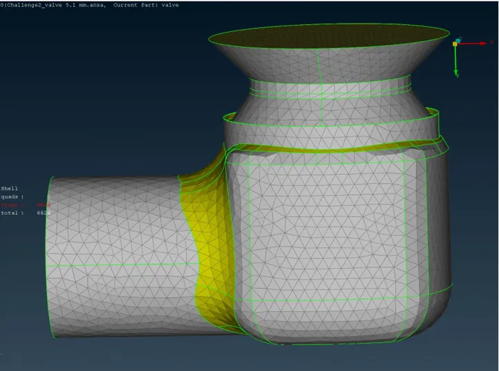
<!-- [if !supportLists]--> · <!--[endif]-->For meshing also we folloe as the same process as in the previous. It shows that the mesh generation is done.
Body Mesh
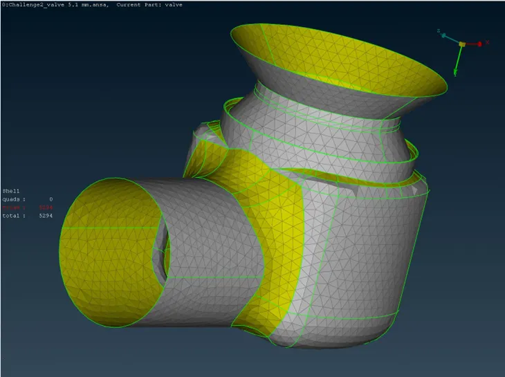
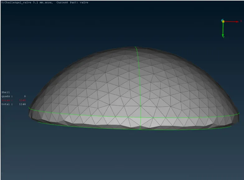
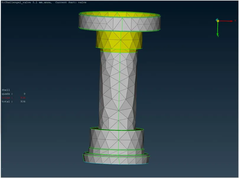
<!-- [if !supportLists]--> · <!--[endif]-->The below image shows that the visible inside the parts after the mesh generation.
Spring Mesh
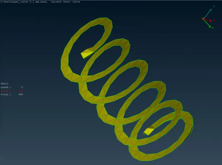
Valve Head Mesh
Column Mesh
Conclusion:
In this detailed meshing procedure for a pressure valve used in Finite Element Analysis (FEA), we focused on several critical steps to create a high-quality surface mesh. The model model inspection, geomentry cleanup, element selection, and quality evaluation, we established a reliable process for accurate FEA.
Starting with CAD model import and inspection, we ensured model completeness and accuracy. Geomentry cleanup resolved common issues like gaps and overlaps, promoting a clean model. The decision for model simplication was made when necessary.
Surface selection and element type and size determination set the stage for an accurate mesh. The surface mesh generation a smooth transition between element sizes and good mesh quality. Validation via messh refinement and quality checks confirmed the mesh’s accuracy.
Conformal interfaces, edge sizing, and validation ensured the mesh’s reliability for the FEA analysis. Documentation of the entire process facilitates reference and collaborations.
This procedure shows that the high-quality surface mesh, providing accurate representation of the valve for the reliable FEA results.