Week 2 Challenge : Surface meshing on a Pressure valve
AIM:
To check for all the geometrical errors in the given pressure valve and to perform a cleanup. After clearing all the geometrical errors in the pressure valve, mesh the surface of the valve using three different set of target lengths. And also to do the volumetric mesh for the fine surface meshed pressure valve.
NEW TOOLS LEARNED:
- Checks Manager (For Geometry Check)
- Cut plane (To view the cross section of the provided object)
- Spacing -----> Auto CFD ( To define the Max and Min Target Length)
- New Face Creation (To create the new faces using COONS, Surface, Fitted, Planar)
- SET PID (To define the various Property ID in a single component)
- Intersect (To clear the any intersection error in the provided geometry)
- Volumetric Mesh (To create volumetric meshined in the provided geometry)
PROCEDURE:
Geometry Error Identification:
In ANSA for identifying the geometrical errors, seperate option is provided named as Checks Manager. Under checks manager we have to select the option Geometry Checks. After that dialog box shown in below appears. On that dialog Box, we have to give Execute Option. After that Errors in the particular geometry is shown.
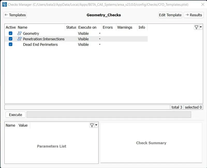
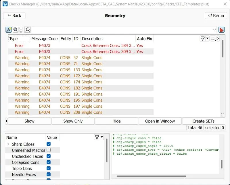
So on the dialog box it shows two erros, Geometry Error and Intersection Error. It will shown depending upon the error in the given geometry. We have to clear all these errors inorder to perform surface meshing. The image above shows the Errors in Geometry in the given geometry. So we have to work upon to clear all these errors.
Error Rectification:
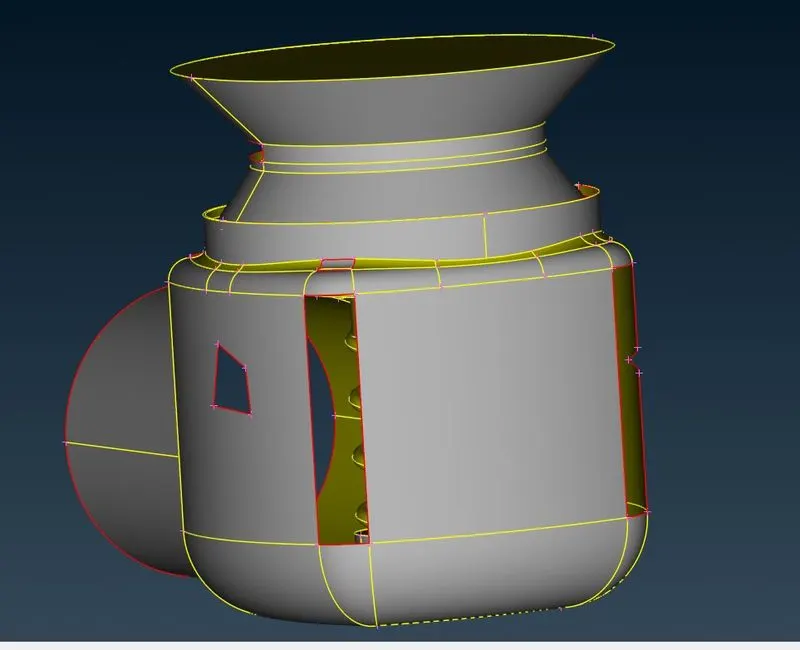
- FACES MISSING:
On the geometry provided in the task, majorly the faces are missing in the outercasing as well as in the column of the pressure valve. So we have to create the faces which match exactly to the outercasing as well as the column in the pressure valve. The missing of faces is shown in the single COONS with the Red colour. To create the missing faces, under the FACES option we have to click the NEW.
Then four types of Face Creation is appear as listed below
- Existing Surface
- Fitted
- Planar
- COONS
So depending on the types of surfaces and the consideration of the faces, we have to choose the option to create a new faces.
- INTERSECTION ERROR:
On the geometry there is another error called as the intersection error. This error occur whenever there is any intersection between the two parts assembled in the drawing. In this geometry the assemble of spring and column is not properly done. The intersection of these two is not done properly. So we have to clear the error inorder to do the surface meshing.
For that initially we have to SET PID, to show ANSA that the spring and column are two different parts. Initially the ANSA take all the parts as a same part with same property. We are very well known that the property of the spring as well as the column and the outer surface.
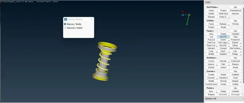
Under the FACES option, there is a SET PID option is there. We have to select the option it will ask us to select the Macros/Shells to define the particular part. we have to select the column and Spring seperately to create the Property. After the property selection is done it will look like in the dialog box attached below. We can coat different colour to identify the part easily.
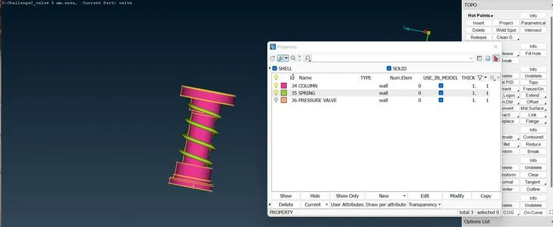
So after the completion of PID creation. Then we have to go the Intersect Option under FACES. It will ask us to select the group 1 and 2, to identify the various parts. So first we have to select the Column and then we have to go for Spring, as the spring is the part assembled to the column. After selecting that the ANSA will find out the intersecting points and it will ask to delete or keep the intersecting parts thrown in a dialog box. So we have to clearly lookinto the geometry and carefully delete the unwanted intersected parts in the geometry.After deleting the intersected parts we can ensure the error clarification through the Checks Manager. If the errors are cleared then we are good to go for the Surface Meshing.
Surface Meshing:
In this we can do the surface meshing by providing the spacing between the target lengths. For that in Perimeter option, Under SPACING Auto CFD option is there. After selection of AUTO CFD option, the Macro as well as Perimeter option is thrown. After selecting the geometry it will shown the Spacing parameter dialog box. It ask us to define the Minimum and Maximum Target Length. It is the tolerances that we can give for the target length. We have to instruct ANSA that within that range only we want to space the target length.
5mm of TARGET LENGTH:
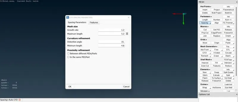
For 5mm of target length, I provide Minimum Target length as 4.8mm and Maximum target length as 5.2 mm. Then we have to go for MESH GENERATION OPTION, CFD -----> Visible. By clicking that it will mesh the part with predefined target length.
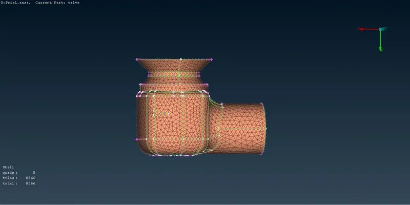
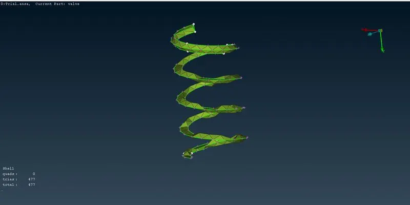
So for the 5mm of Target length, I got number of meshes as follows.
- Pressure Valve(Outer Casing)- 8566
- Column - 1201
- Spring - 477.
3mm TARGET LENGTH:
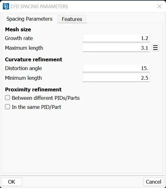
For 3mm of target length, I provide Minimum Target length as 2.5mm and Maximum target length as 3.1 mm. Then we have to go for MESH GENERATION OPTION, CFD -----> Visible. By clicking that it will mesh the part with predefined target length.
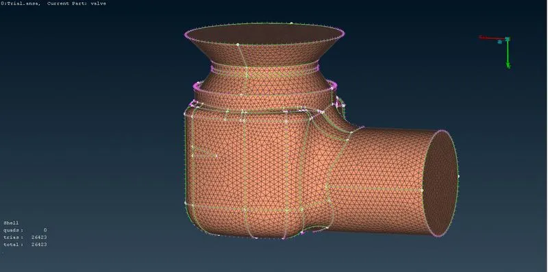
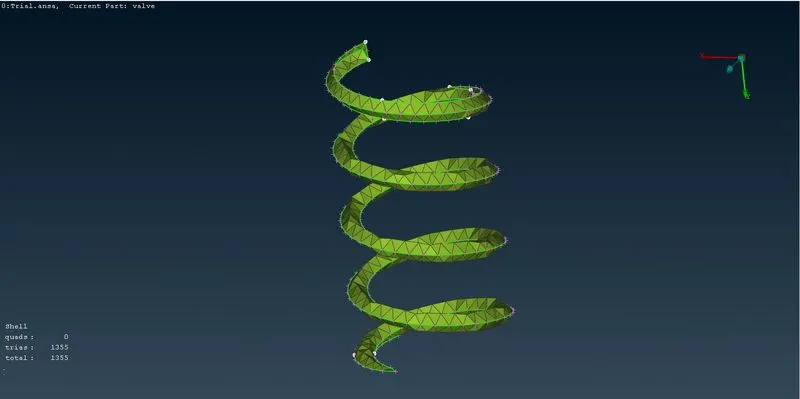
So for the 3mm of Target length, I got number of meshes as follows.
- Pressure Valve(Outer Casing)- 26423
- Column - 3042
- Spring - 1355.
1mm TARGET LENGTH:
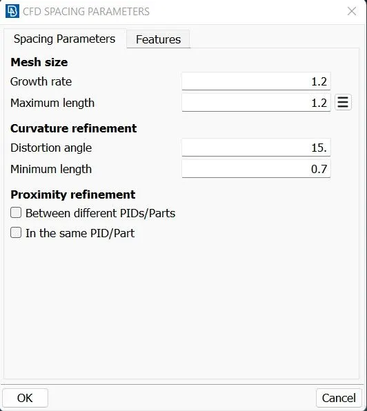
For 1mm of target length, I provide Minimum Target length as 0.7 mm and Maximum target length as 1.2 mm. Then we have to go for MESH GENERATION OPTION, CFD -----> Visible. By clicking that it will mesh the part with predefined target length.
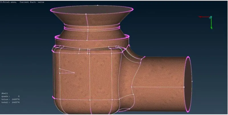
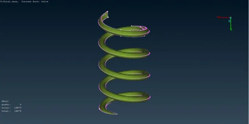
So for the 1mm of Target length, I got number of meshes as follows.
- Pressure Valve(Outer Casing)- 166574
- Column - 15565
- Spring - 14879.
So by doing the surface meshing by the 1mm, 3mm and 5mm. It is clearly seen that the well refined mesh is only obtained while choosing the target length as 1mm.
Volumetric Meshing:
After that we have to do the volumetric meshing. So by the geometry itself we have to clearly understand the fluid flow in the component. It is very clear fluid will flow inside the outer casing outer to the spring and column. So for this column we have to create the volumetric meshing where the fluid will flow.
For that we have to go for the VOLUME MESH DESK. Under that there is option called DEFINE, we have to select the option. The ANSA will detect the volume after we selecting this. For this geometry it shows two volume flow that is possible. We have to clearly select which one by understanding the fluid flow.
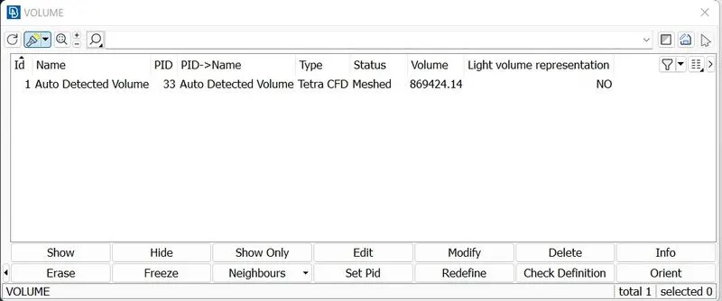
After selecting that we have to choose the type of the mesh. In this I choose TETRA CFD mesh and then we have to click remesh option. Then it will do the volumetric meshing.
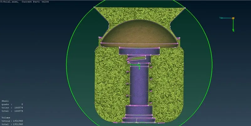
Total meshes in Volume is 1931940. Thus volumetrci meshing is done.
RESULT:
Thus by that with the provide geometry, we find the errors in that. And then clear the errors using the option provided in ANSA. And after the sort out of error three different target length of surface meshing is done. And by the results of the meshing Refined meshing is choosen and the volumetric meshing is done for that geometry.
https://drive.google.com/drive/folders/19onaUczEx96QpTKUiWP_NE8GMCT7Le96?usp=share_link