Surface meshing on a Pressure valve
OBJECTIVE:
- To find geometrical errors in the provided CAD geometry and apply appropriate topological cleanup.
- Surface mesh the pressure relief valve with triangular elements and target lengths of 1 mm, 3 mm & 5m.
INTRODUCTION:
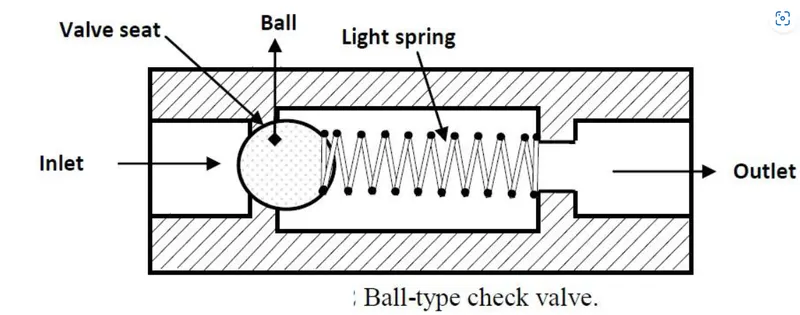
A check valve, also called a one-way valve, is a device that allows the flow of fluids to move only in one direction. The primary purpose of a check valve is to prevent backflow in the system.
A check valve requires a minimum upstream pressure (pressure differential between inlet and outlet) to open the valve called the check valve's ‘cracking pressure.’
Cracking pressure depends on the pressure differential across the valve and spring force & valve weight on the valve seat during operation. Valve design & size for expected flow conditions also dictate the valve response time, valve seat wear, corrosion, etc.
In our CAD geometry, the inlet is oriented vertically atop the valve head and the outlet is at right angles to the inlet in the horizontal plane.
PROCEDURE:
- Topological cleanup
- Geometry repair
- The imported CAD geometry is shown below.
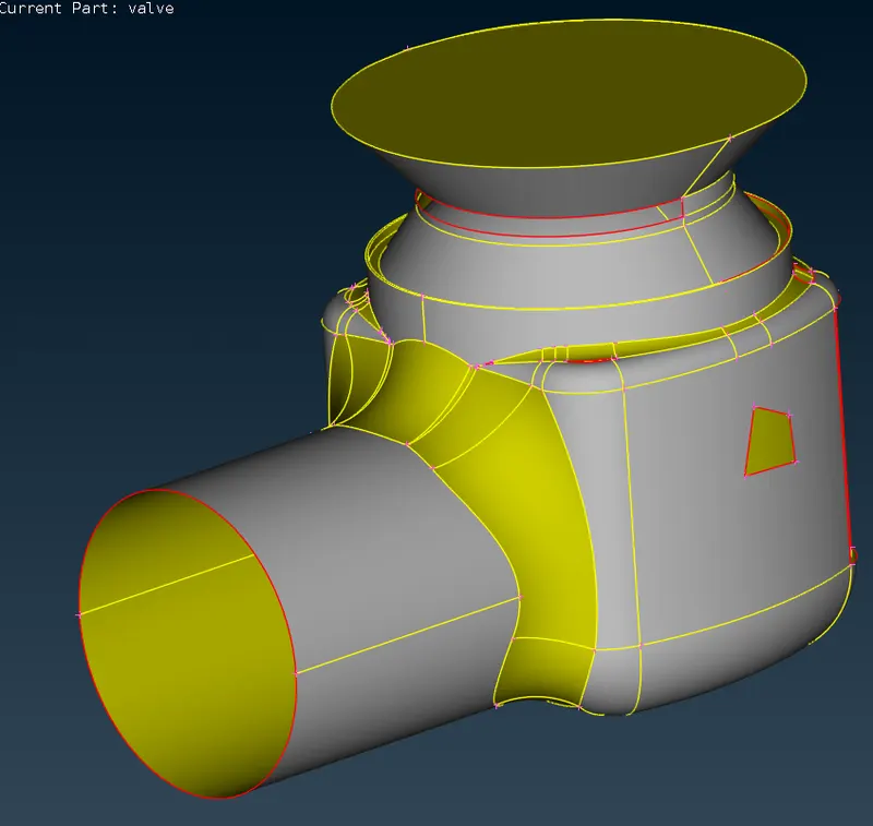
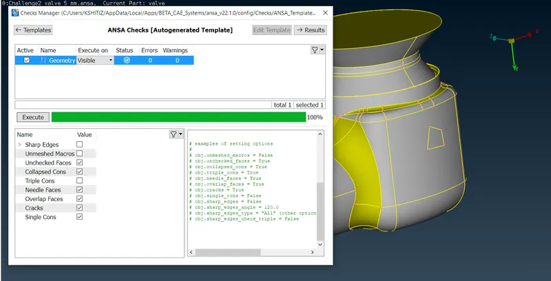
- On performing geometry checks we find 2 cracks & 44 single CONS(indicating open surfaces).
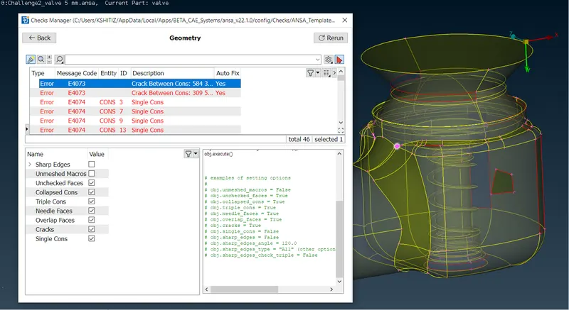
- We have to fill all the cracks & cavities so that no open surfaces (single CONS) are present. This has been done using the tool `"Faces"->"New"`.
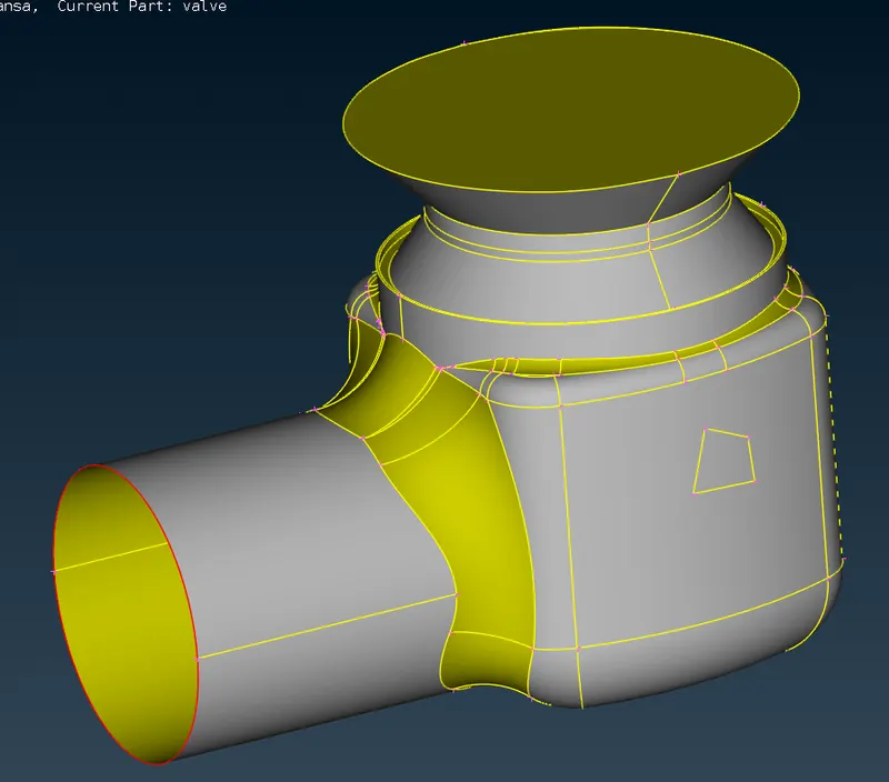
- The imported CAD geometry is shown below.
- Making closed geometry
- Clearly, the left circular single CONS represents the inlet for the check valve so this needs to be closed.
- Although, the bottom of the valve is a double CONS it should show a surface since the valve can't be hollow from the inside.
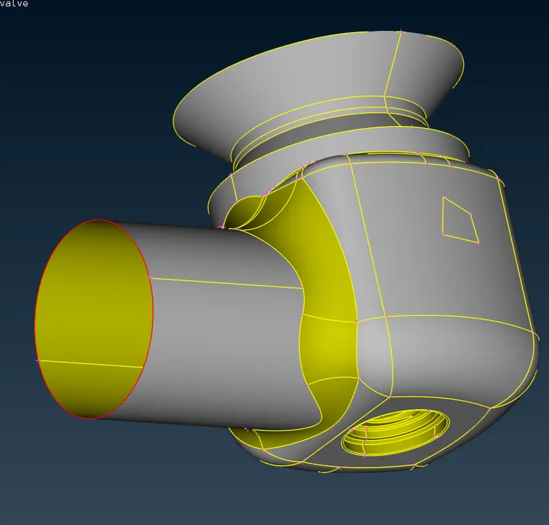
- The wire mesh display shows that no single CONS exists anymore. The triple CONS has formed at the bottom but, it is an accepted surface.
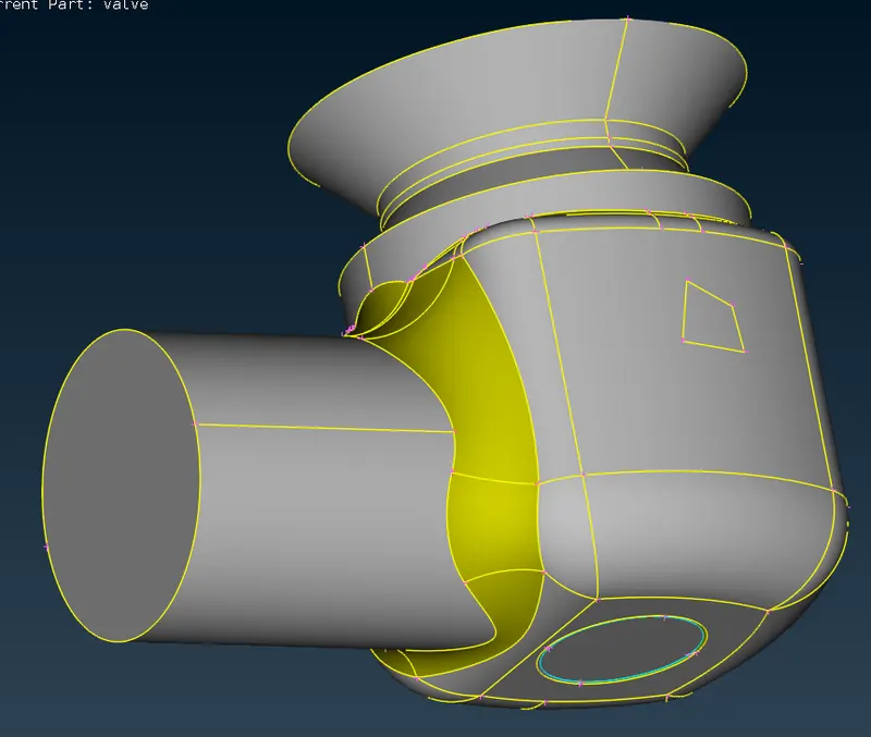
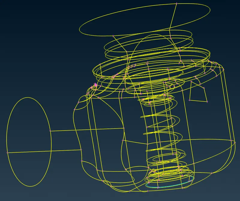
- While making geometry check again we will uncheck triple CONS as it is an accepted curve.
- Defeaturing
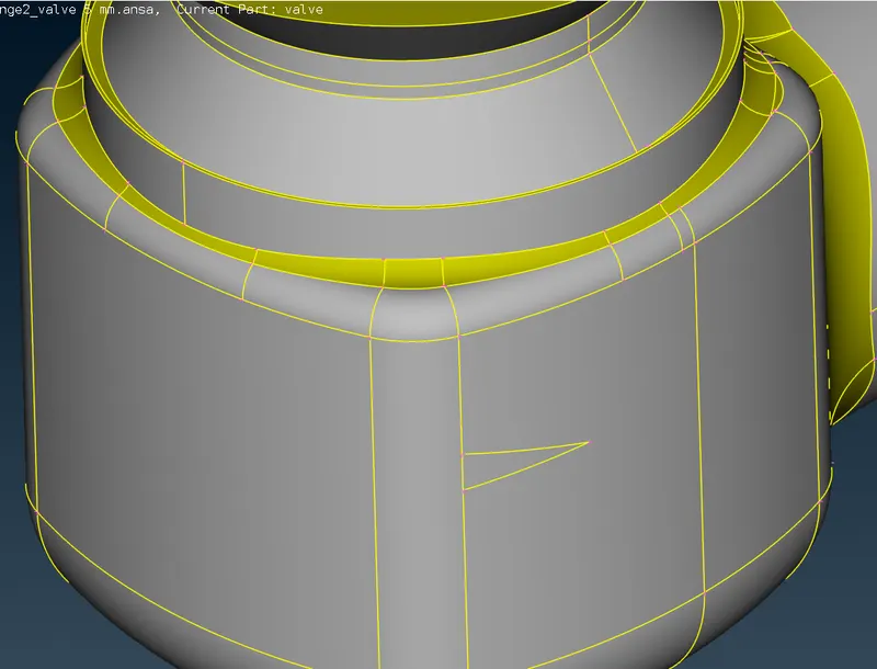
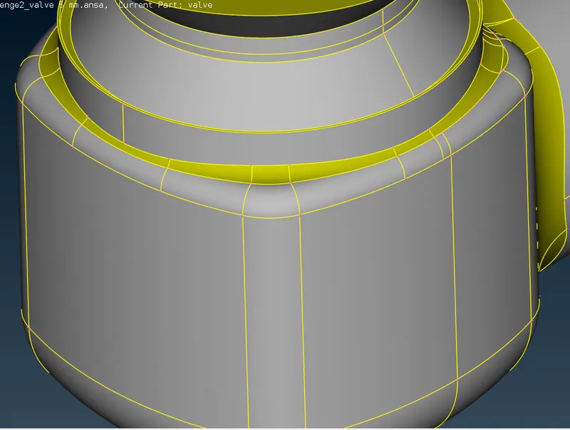
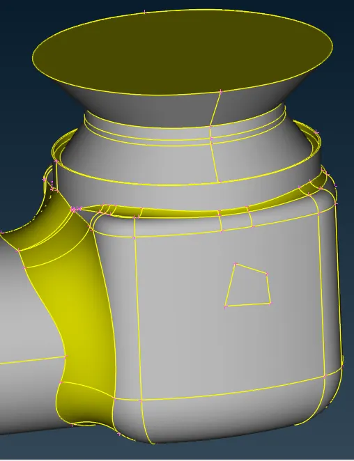
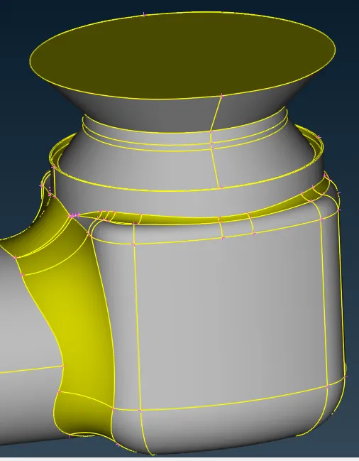
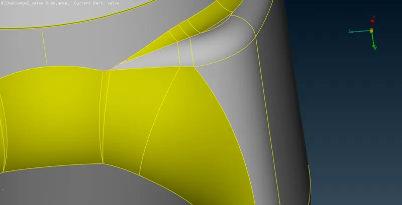
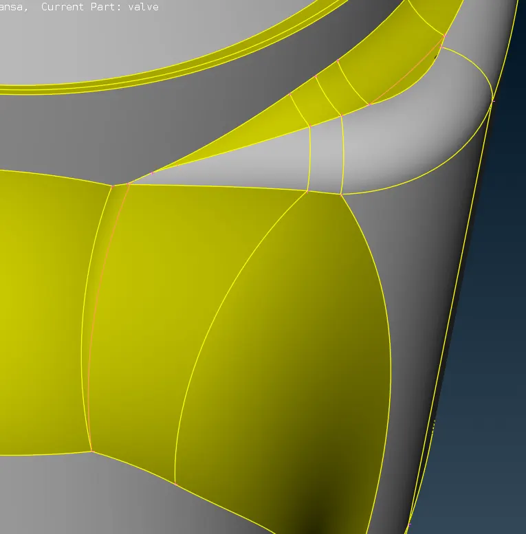
- The CAD model still has some small curves on surfaces (CONS) which will need unnecessary mesh refinements on them to capture their geometry properly.
- Such refinements offer negligible changes in simulation results & insignificant improvement in simulation fidelity.
- The features shown below will be removed.
- Geometry repair
- Setting PIDs
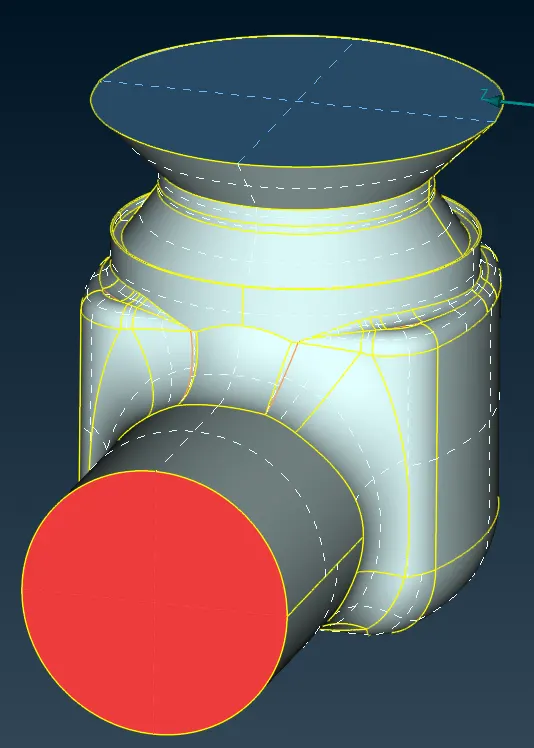
- To simplify meshing, PIDs were assigned to different surfaces of the check valve.
- Body
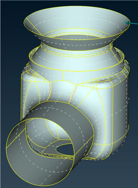
- Inlet & outlet
- Valve head (cyan), valve stem (purple) & spring (green)
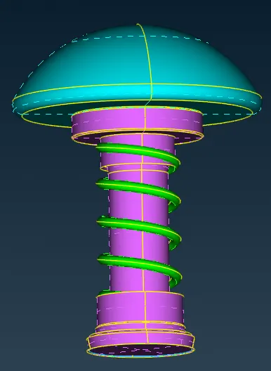
- Meshing
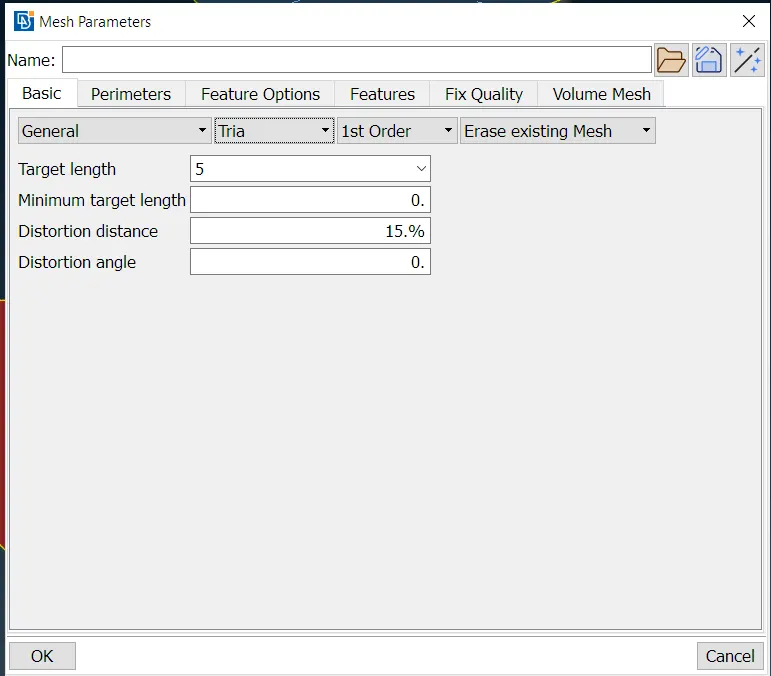
- Mesh parameter settings
- Mesh quality settings
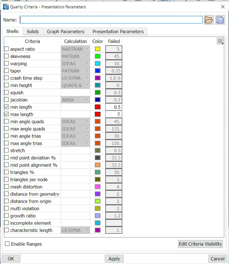
- Mesh parameter settings
RESULTS:
-
- Mesh generated for 5 mm length
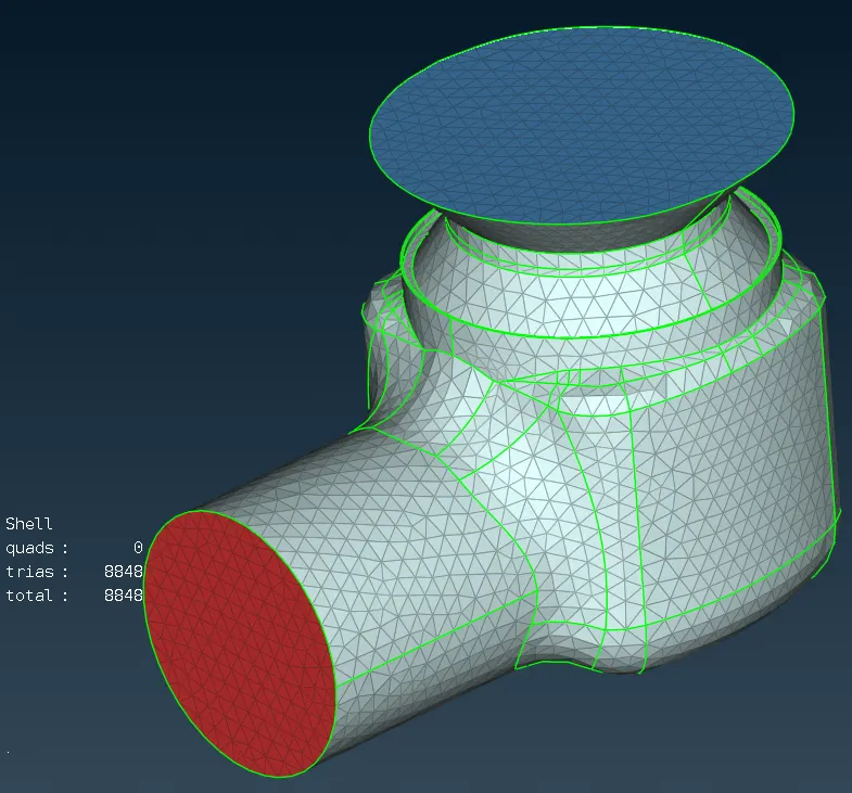
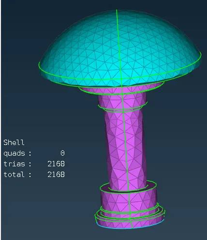
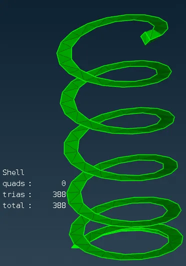
- Mesh generated for 3 mm length
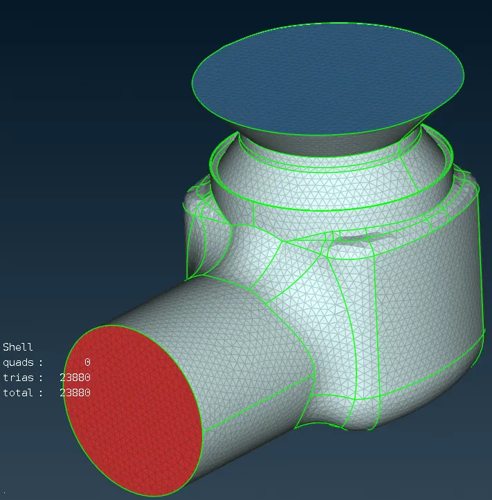
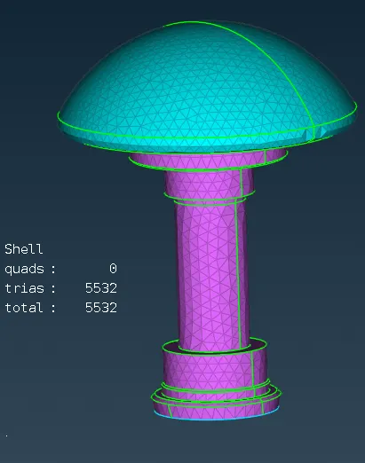
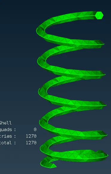
- Mesh generated for 1 mm length
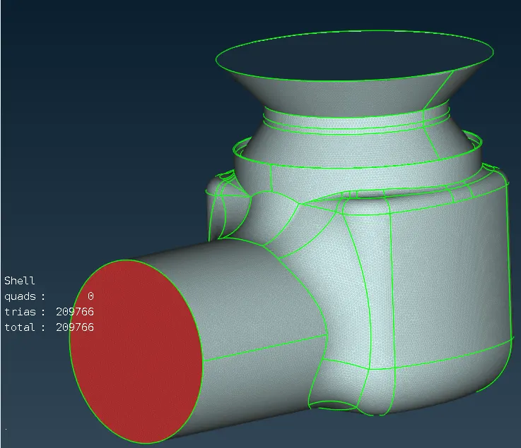
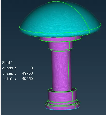
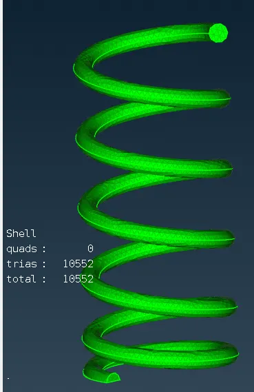
- Mesh generated for 5 mm length
CONCLUSIONS:
- It can be seen that meshes with smaller element sizes capture the geometry better but this comes at increased computation time during simulations.
- From the perspective of capturing the geometry, we can see that from the above results the optimal mesh size for the body, inlet & outlet faces is 5 mm, for the valve head & valve stem 3 mm and for the spring 1mm.
- Following this element sizing scheme will result in the best geometry capture & optimal simulation times.