Week 2 Challenge : Surface meshing on a Pressure valve
Aim
Perform a topology cleanup on the given pressure valve geometry and generate a surface mesh using triangular elements with lengths of 1, 3 and 5mm.
Learning Outcomes
- Perform topological cleanup on the various faces of the model
- Understand and rectify the various errors and warnings shown in the geometric checks.
- Construct a triangular surface mesh on the model using various element sizings
Procedure
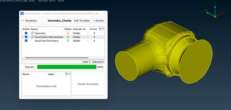
The given pressure valve geometry was opened in ANSA v23 as shown in the image below.
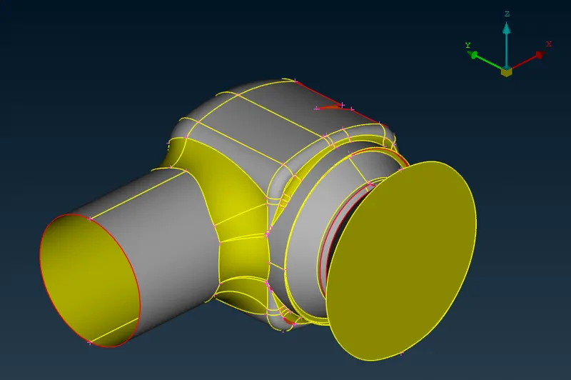
From the image above, a large number of singles CONS (Curves ON Surfaces) can be seen on the model which needs to be addressed during the topological cleanup.
Considering an internal simulation, using the Orient tool all outer faces of the model were flipped to ensure the yellow side faced outward. The resulting model can be seen in the image below.
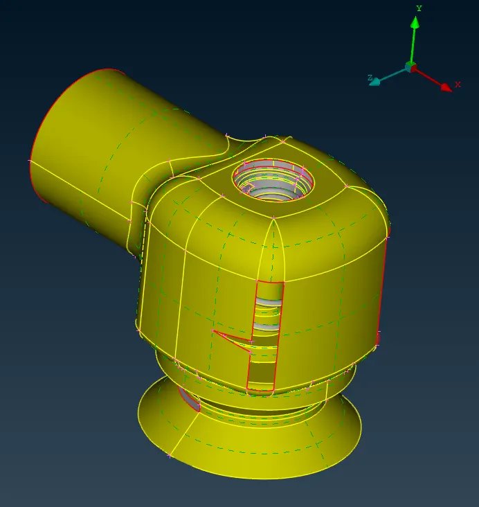
The various holes and broken faces in the model were fixed by creating new faces using the COONS method as shown below.
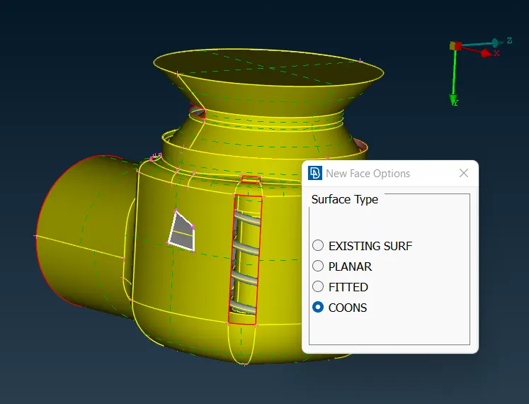
The image below shows the created face over the hole.
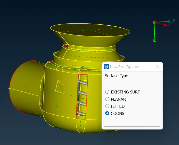
In the image shown below, a curve was created connecting the two points to ease the face creation.
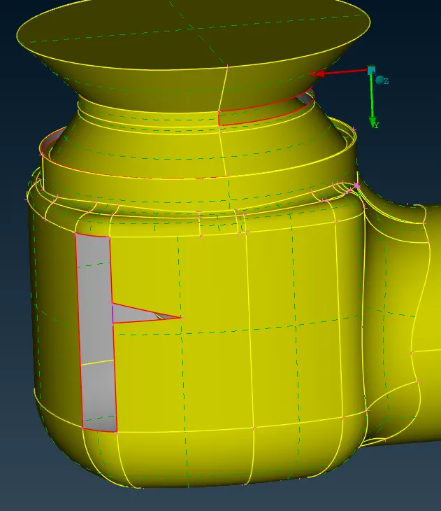
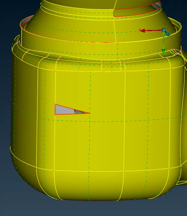
The resulting face can be seen in the image below.
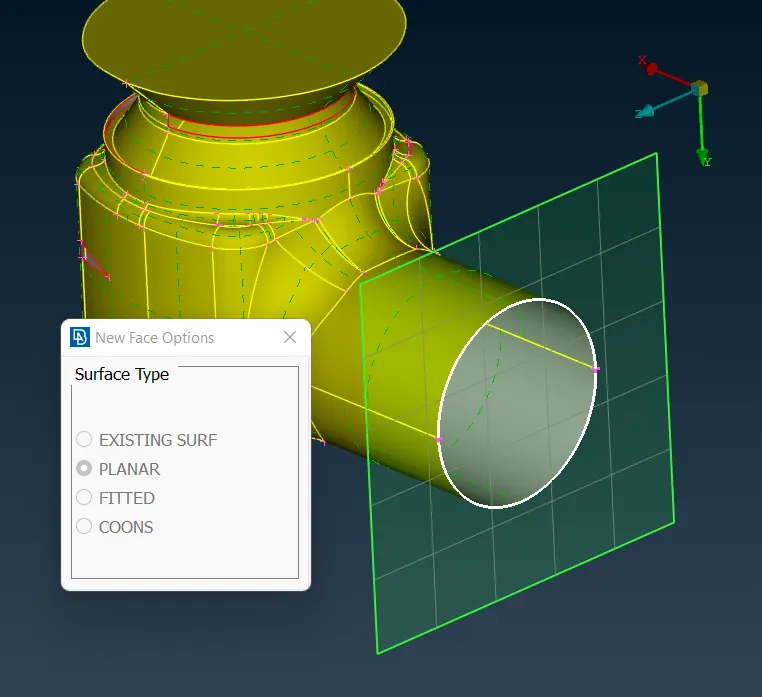
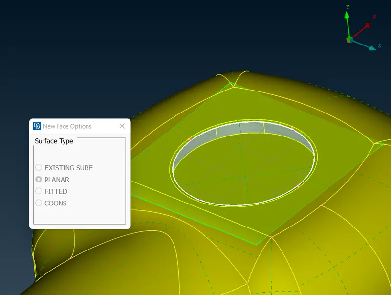
The Planar method was used to create the face at the front of the model as shown in the image below.
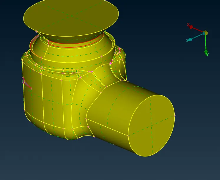
The resulting face can be seen in the image below.
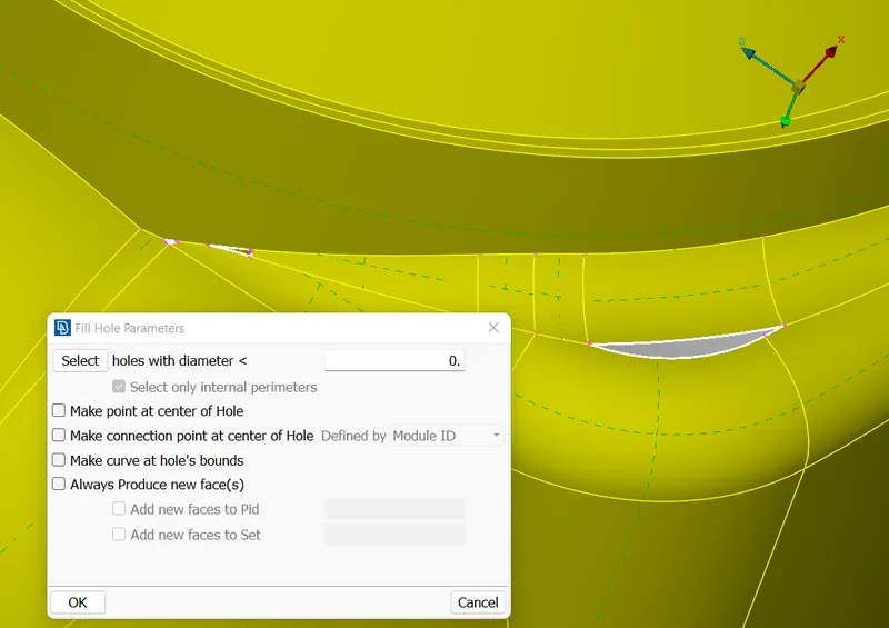
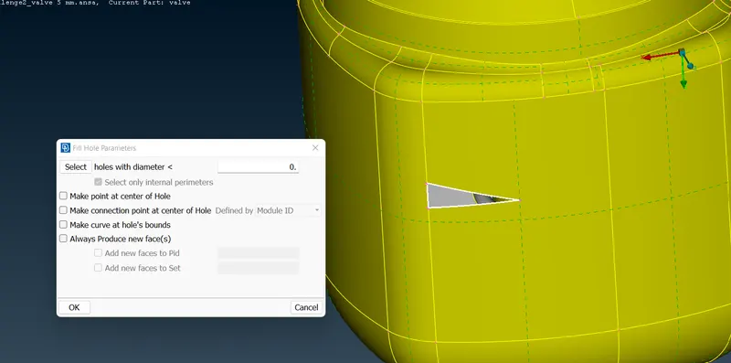
The various small holes in the model were fixed using the Fill Holes tool as seen in the images below.
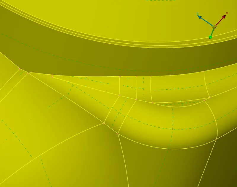
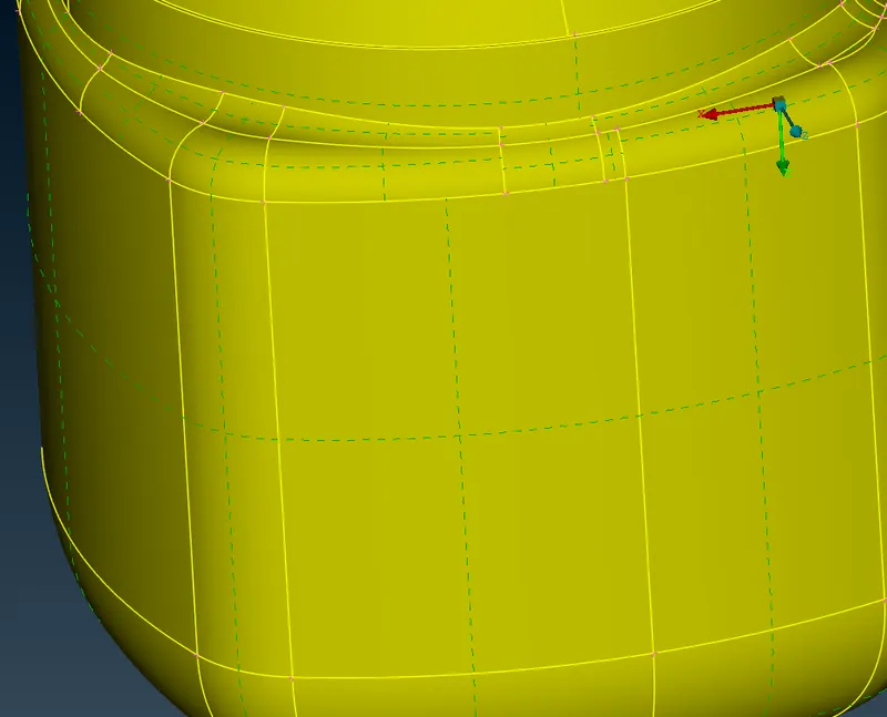
The resulting fixed faces can be seen in the images below.
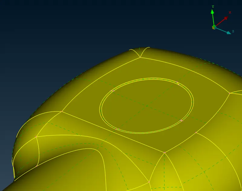
The planar method was used to create the face at the base of the model as seen in the image below.
The resulting face can be seen in the image below.
Now that all the faces in the model are patched up, the unwanted edges in the model are removed using the Modify tool as shown in the images below.
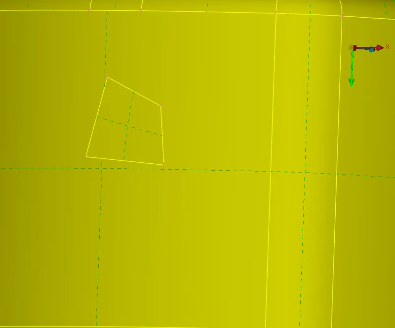
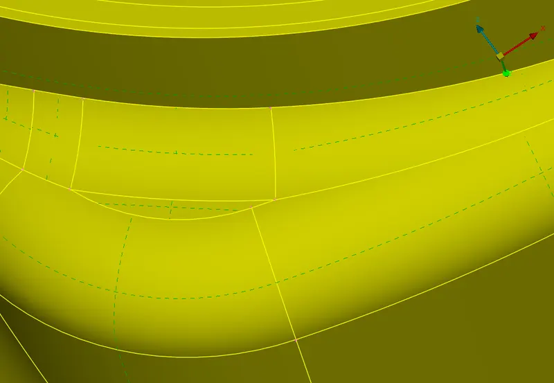
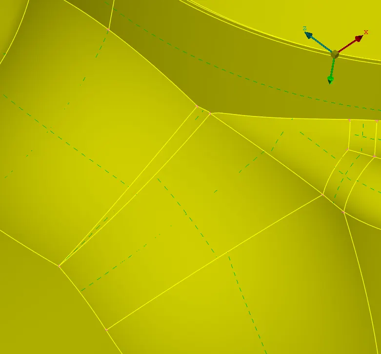
The resulting cleaned faces can be seen in the images below.
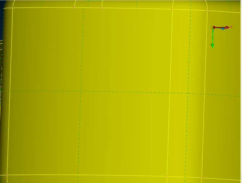
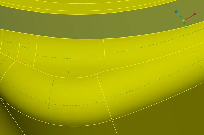
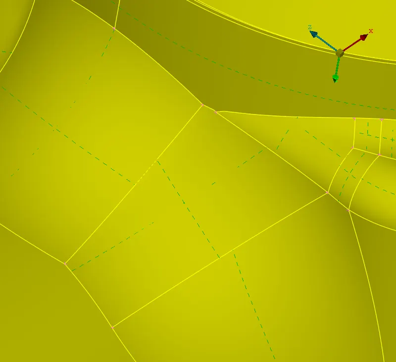
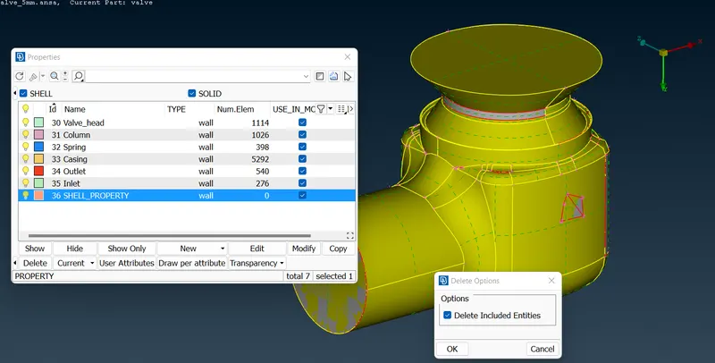
With all the major holes and faces cleaned, PIDs were created and assigned to the respective bodies as shown in the image below.
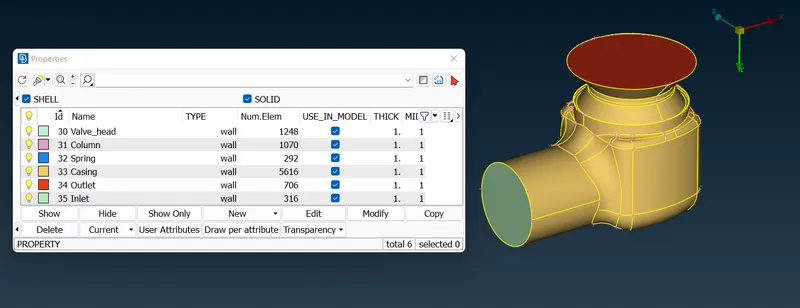
Running the penetration check showed an intersection error between the spring and the column PIDs as seen in the image below.
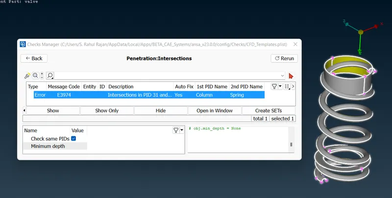
To overcome this error, the intersect tool was used and the PIDS were selected accordingly as seen in the image below.
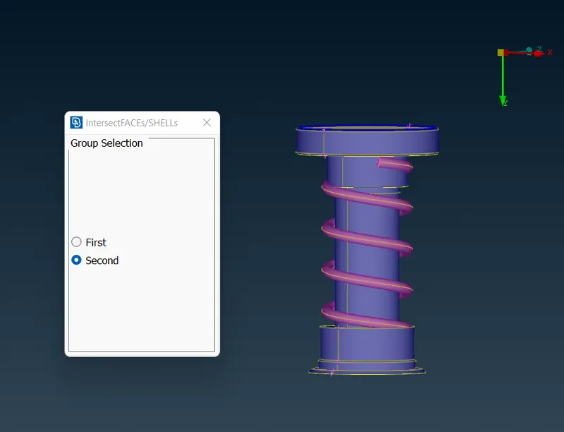
The intersection tool required certain faces to be kept or deleted as shown in the image below.
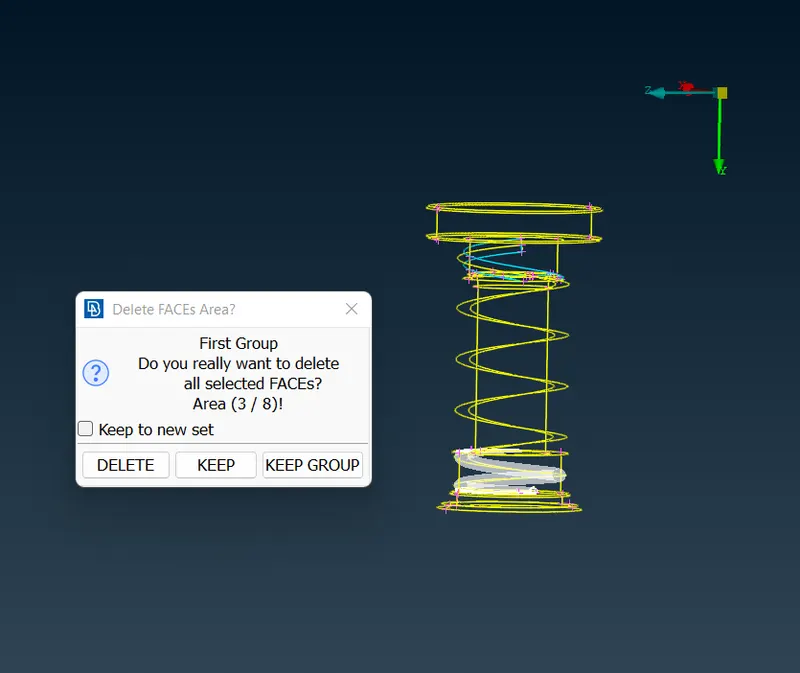
The final clean spring and column geometry can be seen below.
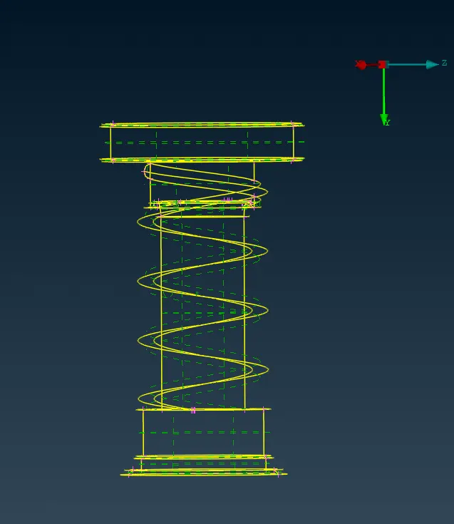
To remove the undeleted faces from the model, the faces were enabled using the undelete tool as seen in the image below.
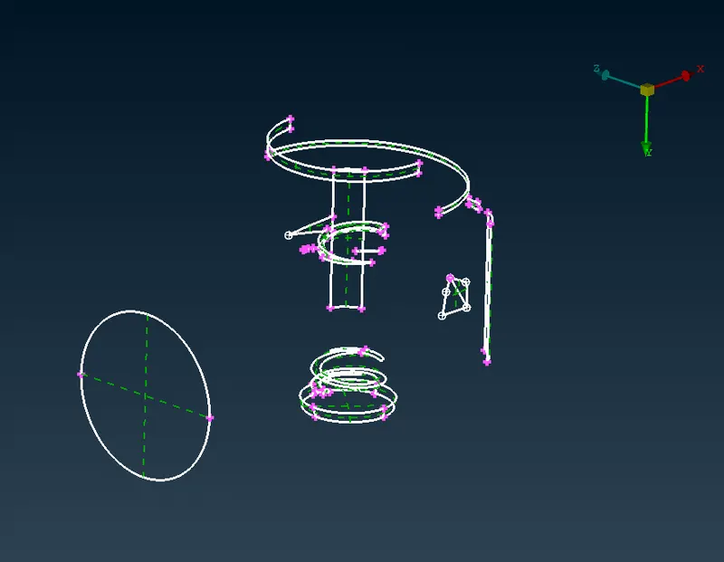
The faces were then selected and deleted as shown in the image below to remove extra faces which were maintained during the clean-up phase.
The final topology cleaned model can be seen in the image below.
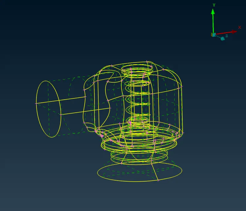
The geometry check was performed to verify the cleanup as shown below.
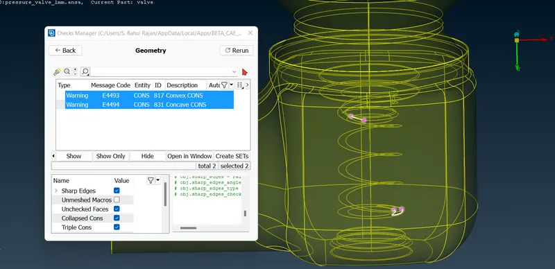
The warnings from the geometry cleanup are shown in the image below. The message displays the creation of convex and concave CONS on the surfaces of the spring. This can be attributed to the intersection conducted between the spring and the column PID. This warning may be ignored for the topological cleanup phase for now as generating a surface mesh over the faces will enable proper definitions of these surfaces. Knowing the location of these warnings is crucial to ensure the surfaces can be meshed appropriately.
With the topological cleanup completed, the triangular surface mesh may now be generated using the sizing lengths of 1,3 and 5mm.
An initial perimeter sizing was conducted on all the edges of the model. The Length tool was used to perform the sizings. The image below shows the perimeter sizing for the respective cases.
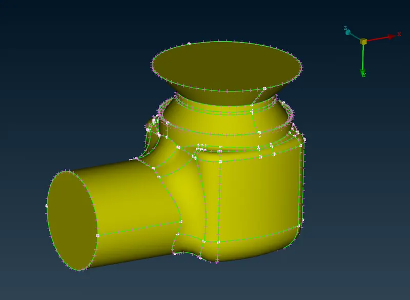
5mm Case
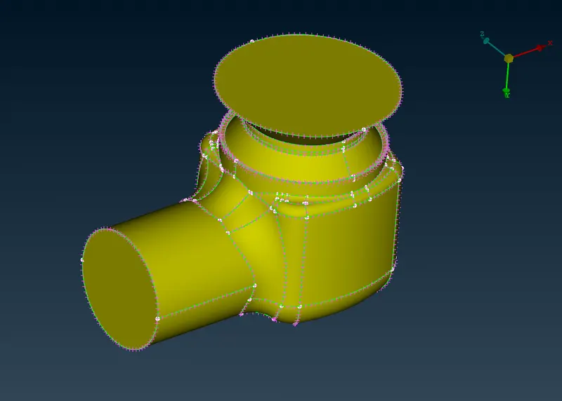
3mm Case
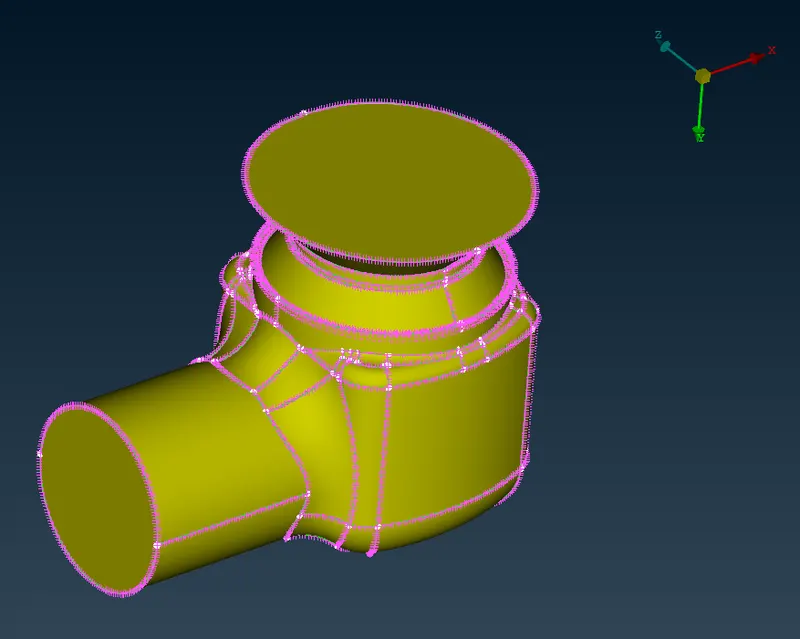
1mm Case
The surface mesh was then generated using the SpotMesh method using the respective element sizings as shown in the images below.
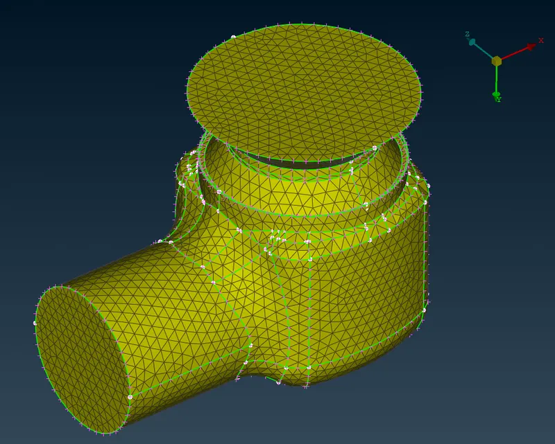
5mm Case
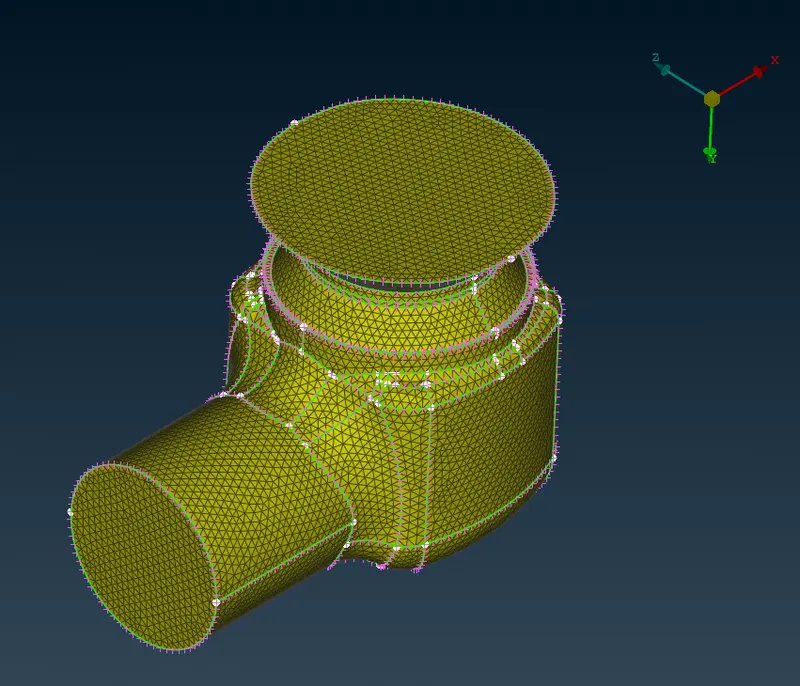
3mm Case
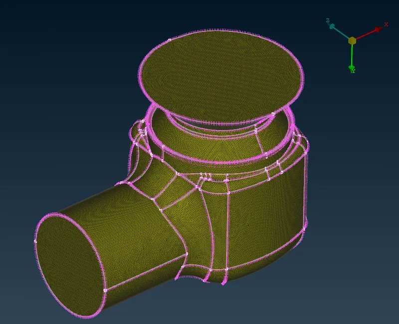
1mm Case
Results
Case 1: 5mm Element Sizings
The image below shows the surface mesh on the 5mm case with edge lengths measured. A total of 9248 triangular cells were generated.
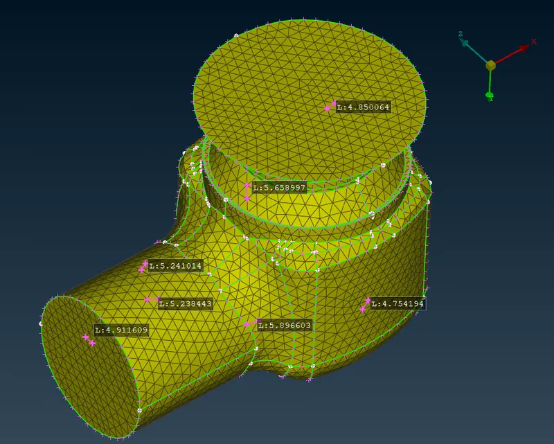
From the image above, the major features of the outer casing have been captured by the mesh. However, the mesh fails to capture the curvatures on the casing and so refinement of the mesh is required in those regions.
The images below show the surface mesh on the column and spring PIDs.
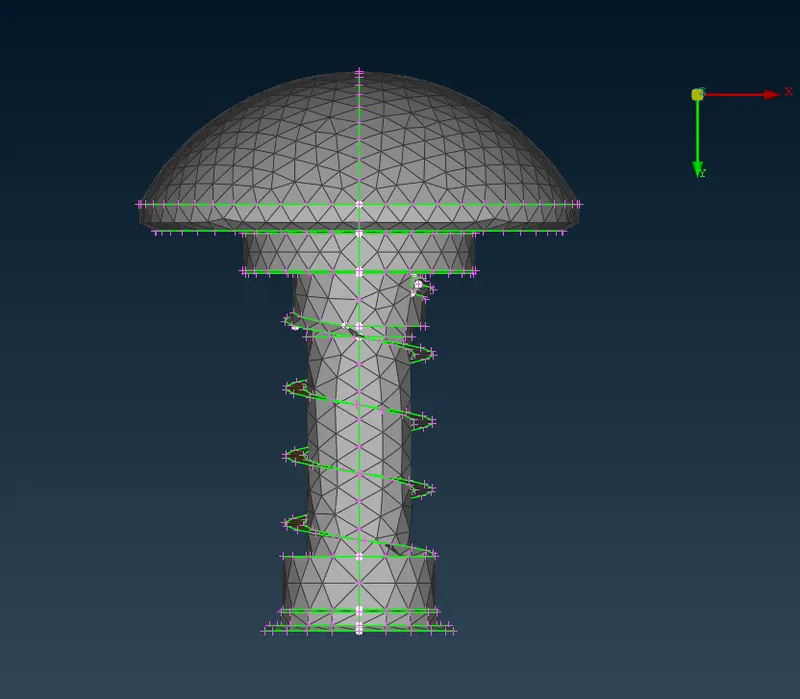
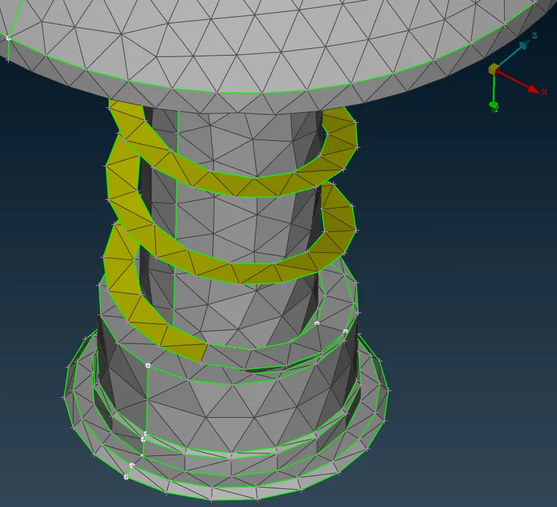
From the images, it is evident that the 5mm sizing is unable to capture the curvature of the springs and leads to a very thin arrangement of mesh elements. Refinement of the mesh is required in these regions.
Case 2: 3mm Element Sizings
The image below shows the surface mesh on the 3mm case with edge lengths measured. A total of 24220 triangular cells were generated.
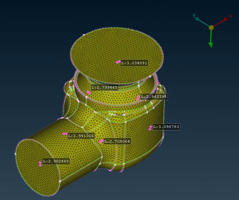
From the above image, the major features and the curvatures on the outer casing have been captured well by the mesh. Additional coarsening may be performed on the flat surfaces of the model where curvatures are not present to reduce the total cell count.
The images below show the surface mesh on the column and spring PIDs.
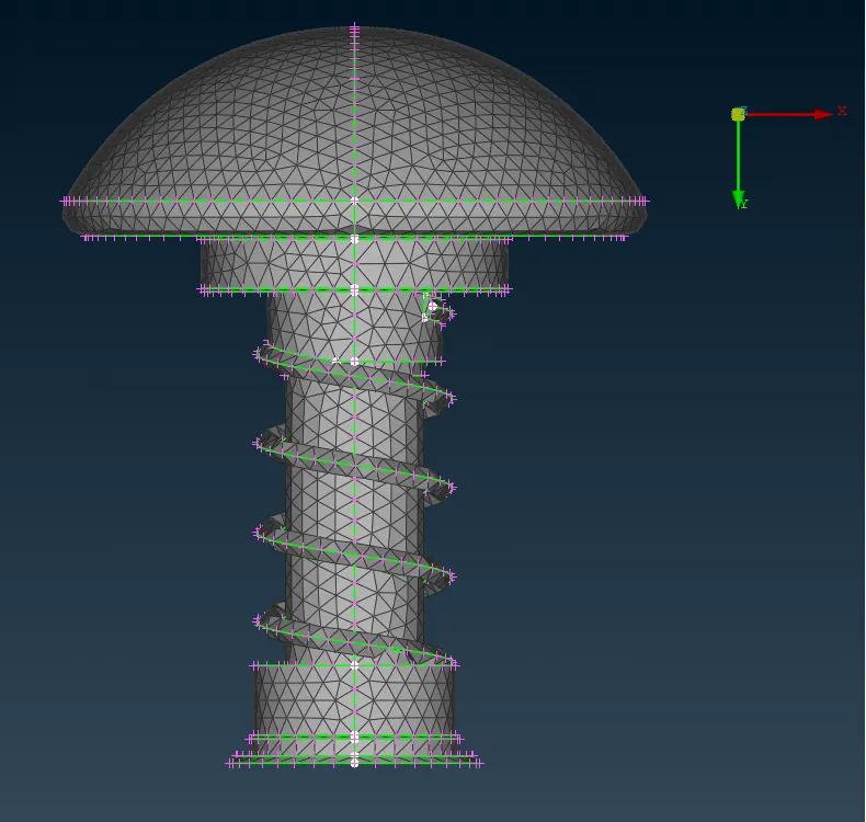
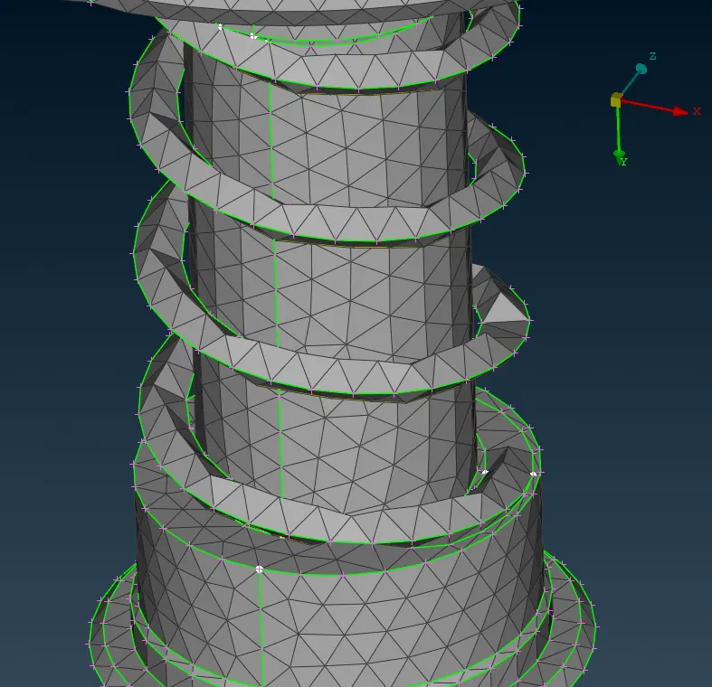
From the images, the 3mm sizing is able to capture the 3-dimensional nature of the springs however fails to resolve its curvature. Further refinement of the mesh is required in these regions.
Case 3: 5mm Element Sizings
The image below shows the surface mesh on the 1mm case with edge lengths measured. A total of 209642 triangular cells were generated.
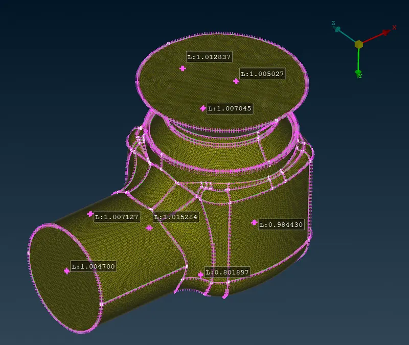
From the above image, the major features and curvatures of the outer casing are well captured. However, a major portion of the outer casing is flat and does not require such refinement. Using such a fine mesh will lead to a vast increase in computational cost with negligible improvement in the results. Hence, coarsening can be done in regions of the model where curvatures are not present to significantly reduce the total cell count.
The images below show the surface mesh on the column and spring PIDs.
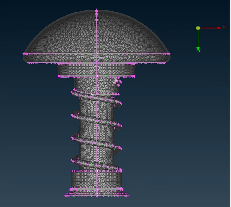
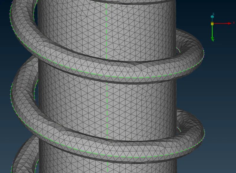
From the images, the 1mm sizing is able to capture the curvature of the springs well. There are still deformations in the curvature which may be fixed upon refinement. Refining this region further is however optional and based purely on the aims of the simulation and desired fidelity.
Conclusion
The given pressure valve geometry was topologically cleaned and surfaced meshed using triangular elements of 1,3 and 5mm sizings. On the outer casing, the 3mm sizing was able to capture the necessary details well. The 5mm sizing under-resolved the curvatures of the casing and the 1mm sizing over-resolved the casing leading to a large cell count. On the spring, the 1mm sizing was seen to sufficiently capture the curvature well. The 3mm sizing was seen to capture the 3D nature of the spring but failed to resolve its curvature and the 5mm sizing was unable to capture neither the 3D nature of the spring nor the curvature leading to a very thin mesh. A mesh with a 3mm sizing on the outer case and 1mm sizings on the inner springs may be a viable option to sufficiently capture the details of the model and have lower computational cost.