Week 2 Challenge
1.BIM stands for "Building Information Modelling"
what is BIM?
BIM is a tool used for the planning, design, construction, and management of the building and other projects.It is a 3D modelling software.
BIM classified into two types;
-->:coordination.
-->:computation.
Coordination helps multiple people work together on the same project simultaneously with effificient time.it also increases accuracy.
Computation majorly involves calculation and schedule planning.the benefits of computaion are energy evaluation,material schedule etc...
The benefits of BIM over 2D CAD are:
1.BIM provides a set of predefined information that can provide useful data for calculating project cost,thermal performance aspects,maintenance,structural,etc...
2.Drastic reduction of errors.
3.Complex models are also easy to generate when compared over 2D CAD.
4.Time saving processes.
5.preconstruction project visualization.
2. Revit Categories, Family, Elements, Instances.
.Category: revit components falls into some categories some of then are pipe fittings,lighting fixtures.
.Family:family in the revit is a group of 2D and 3D information tools.
.Elements:the elements are controlled and defined by familes
.Instances:these are useful for installing families.
AIM:
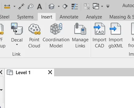
Go to inseret tab and choose a category, pick a family and element.
TOOLS USED:
>Insert tab.
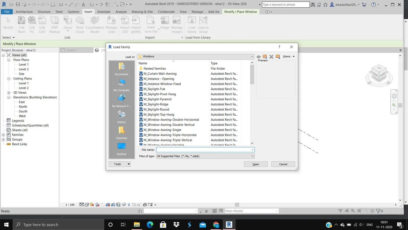
>load family.
>file name.
>open.
PROCEDURE: (Note: Download the families from the chrome to insert)
1.Firstly open revit and select architectual template.
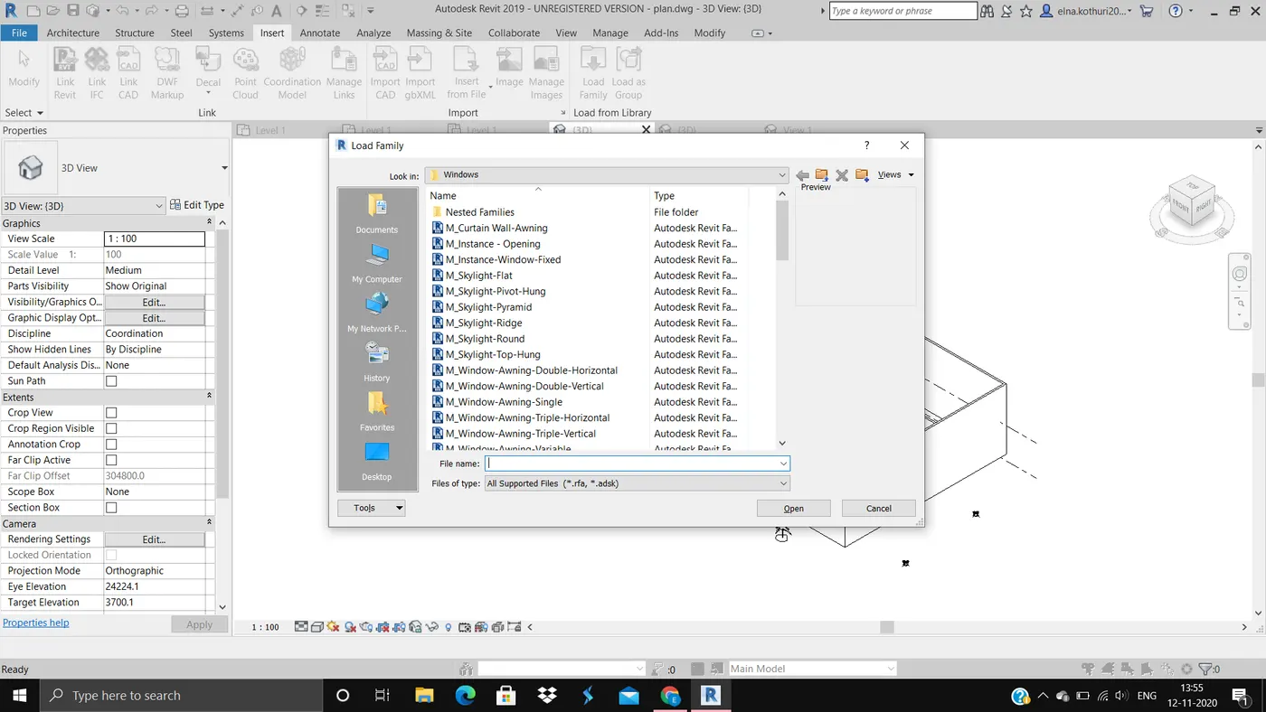
2.Click on the insert menu.
3.Choose the load family.
4.Now you can see the dialog box of load family select an component form it.
5.Now click open.
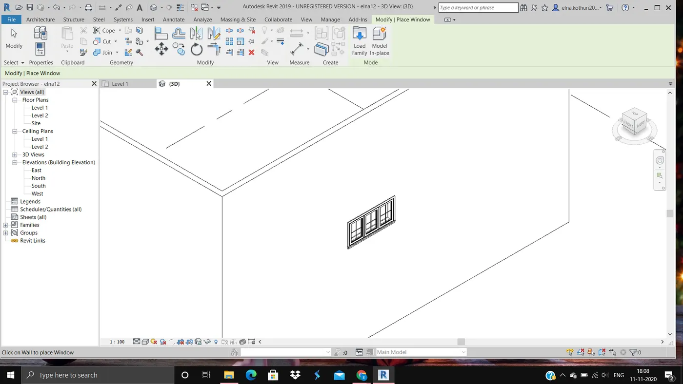
6.Go to architecture window and select the object.
7.Drag and place it on the model where you want.
RESULT:
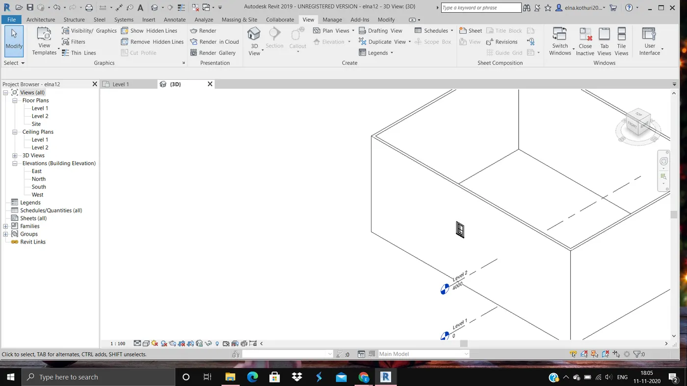
By following the above procedure we can insert the components and families in our model.
3.AIM: To open a project file with architectural template.saving the file with appropriate name.setting up the projet units, completing the project information and setup maximum backups for project file 3.
TOOLS USED:
>Revit 2019
>New
>Save as
>Manage
>Project units
PROCEDURE:
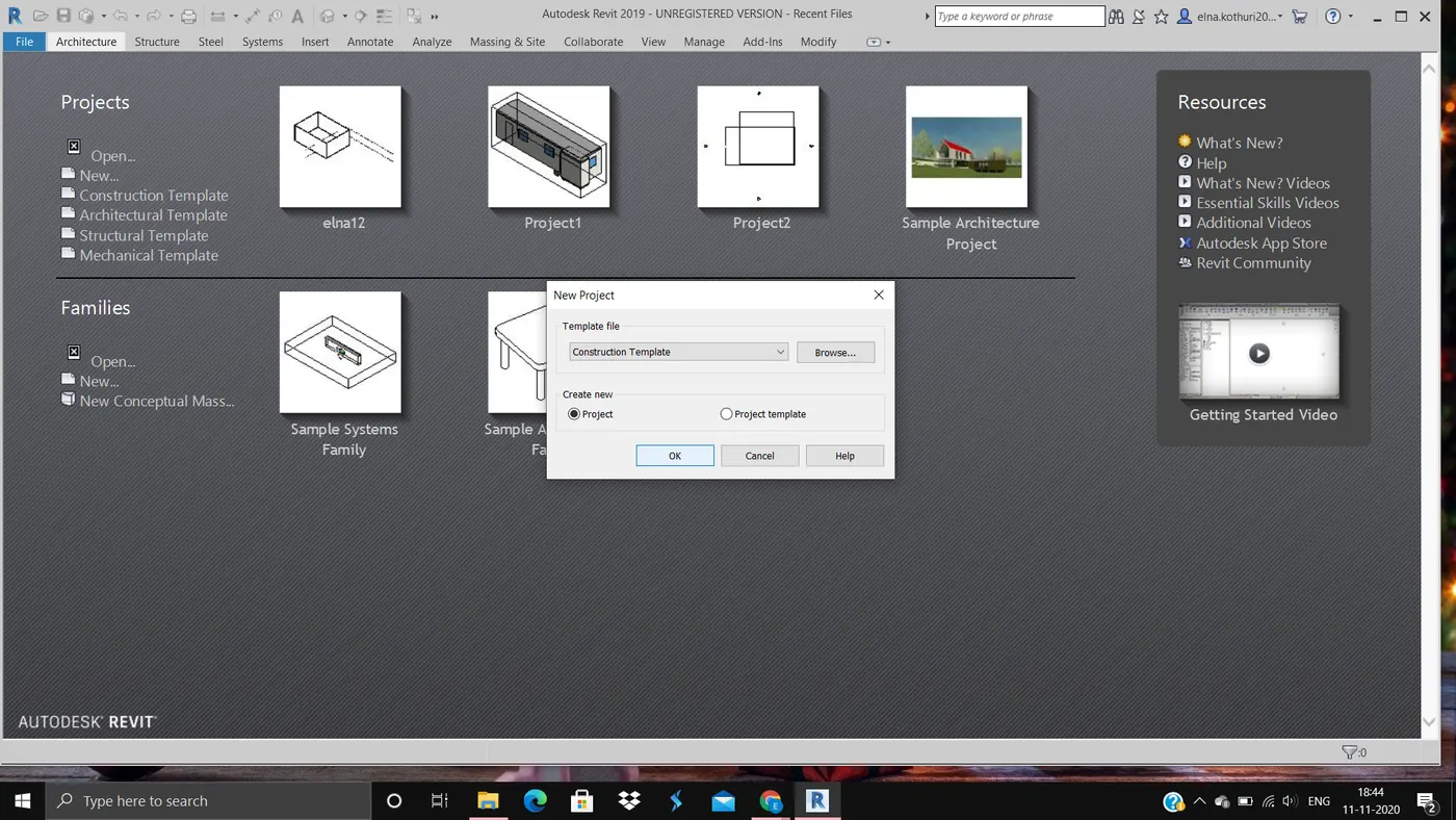
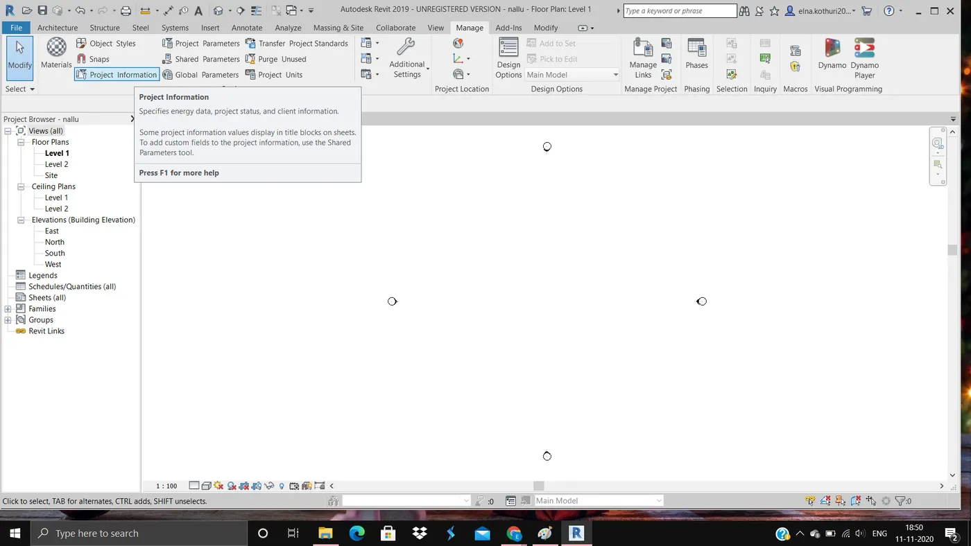
1.Open revit,and click on "NEW tab".
2.Click on architectural template and click ok.
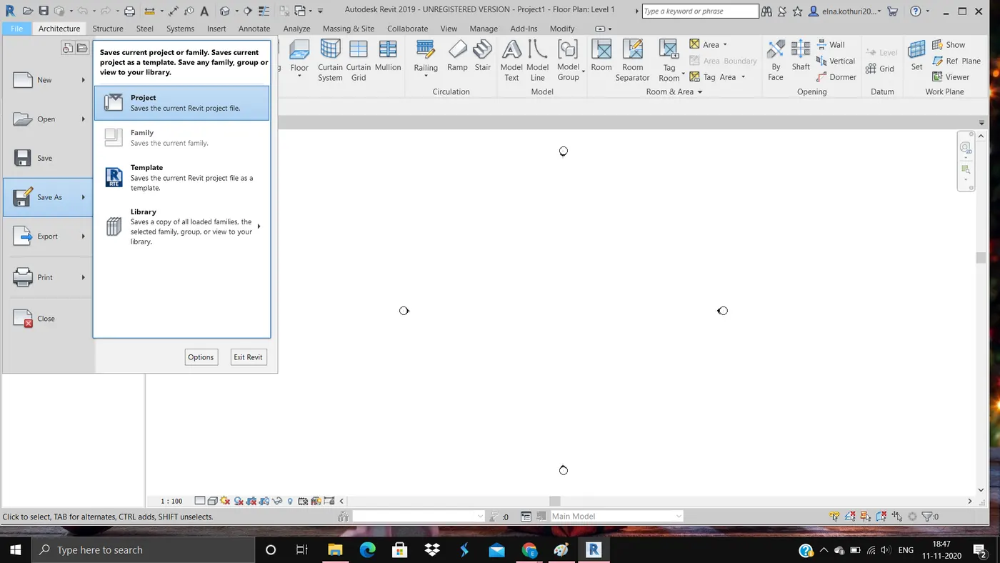
3.click on file menu.
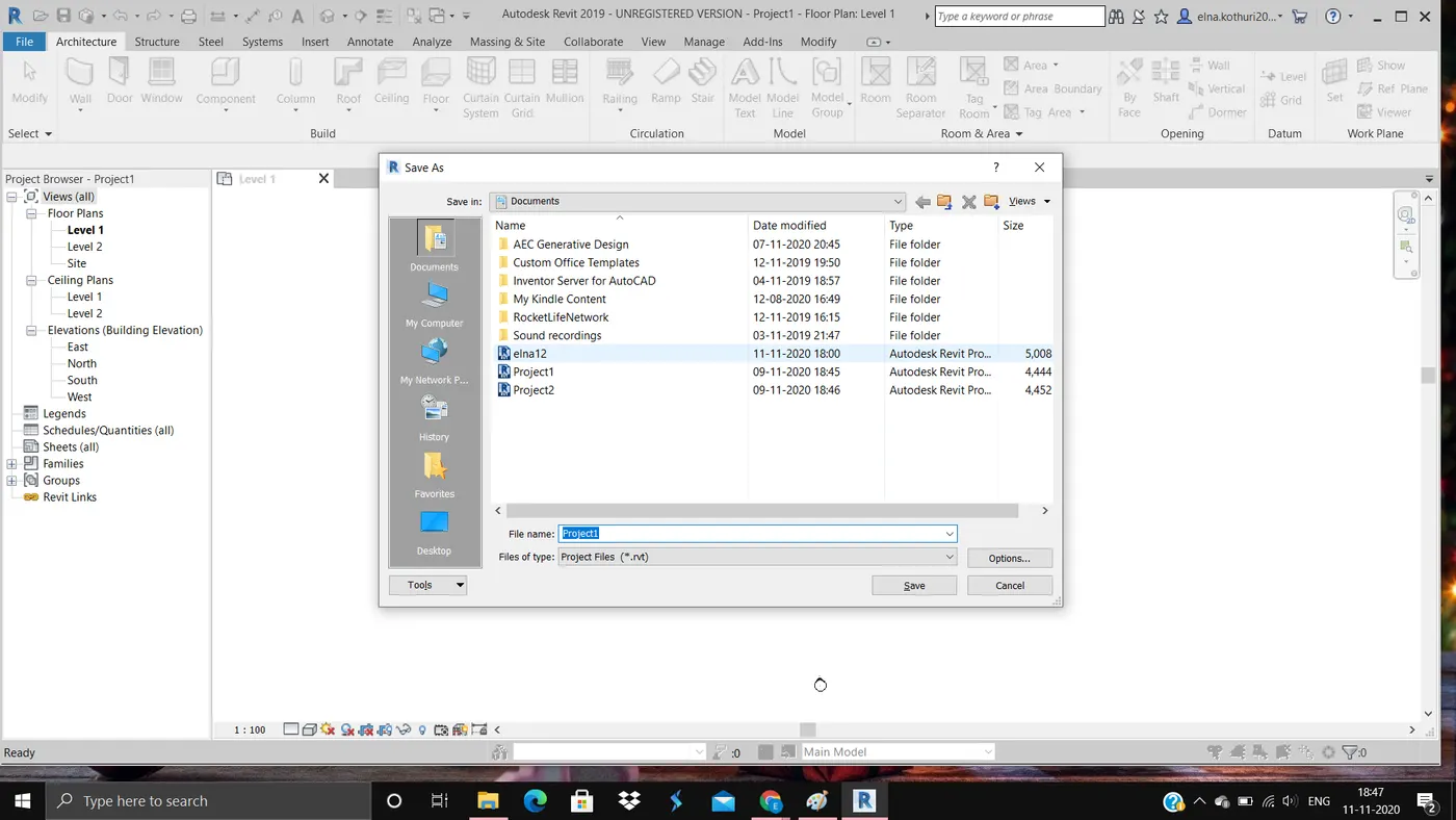
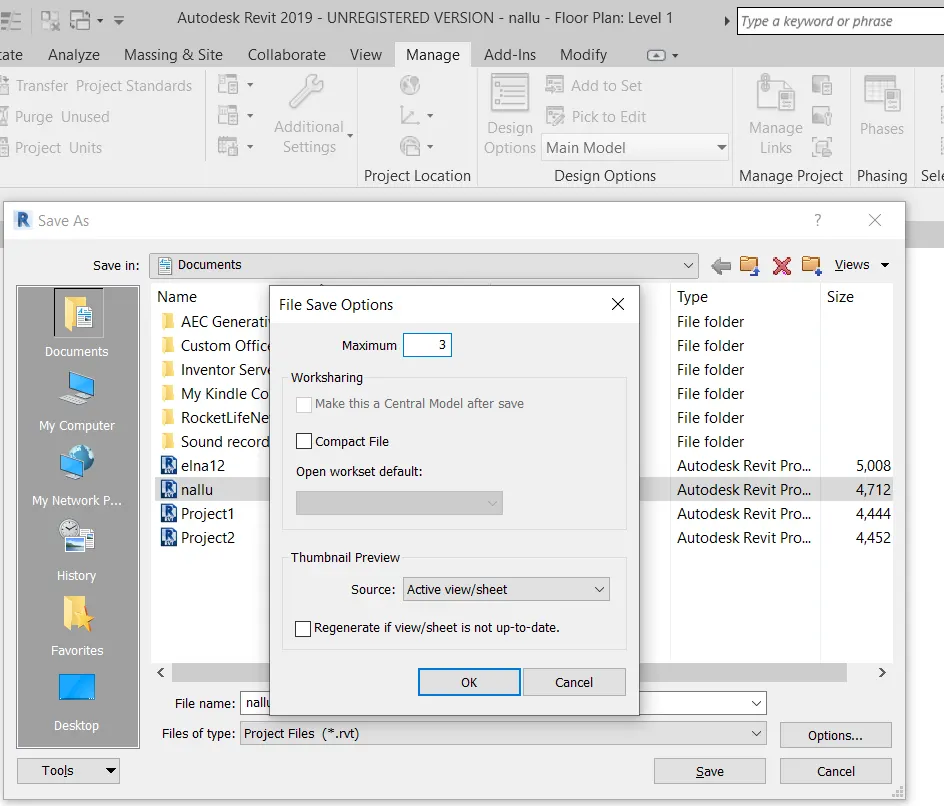
4.Select save as option and click on project and save it.
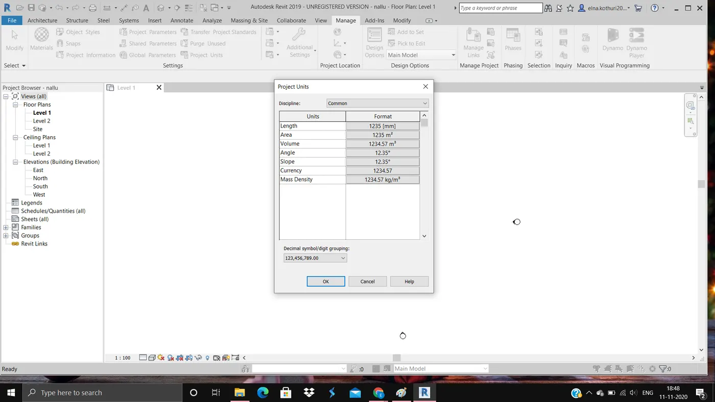
5.Choose the manage menu to change the project units.
6.click on the project information and complete the details and do maximum upto 3 backups.
RESULT:
We can open a project file and save it with a appropriate name and set it upto maximum 3 backups by following the above steps.
4.What are the levels and Grids;
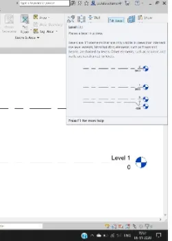
>Levels:Levels are used to represent the floors in the elevation.
>Grids:Grids are used to represent all the walls with the base of horizontal and the vertical lines.
AIM:
>ground floor at 0'
>first floor at 10'
>second floor at 20'
>roof at 30'
Transverse grids A,B,C,D,E @10' spacing.
Longitudinal grids 1 to 10 at 20' spacing.
TOOLS USED:
>Architecture.
>Grid.
>Levels.
PROCEDURE:
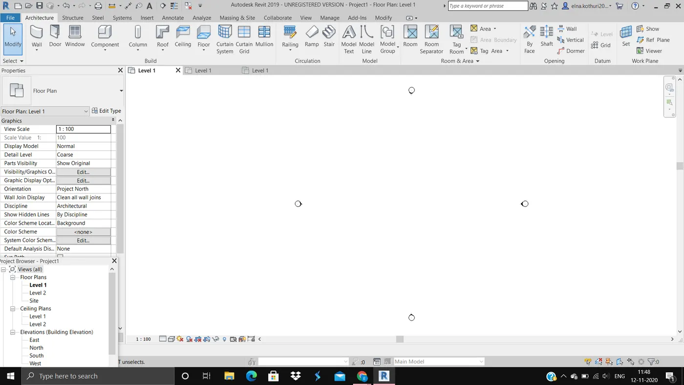
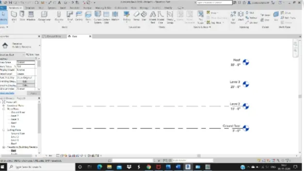
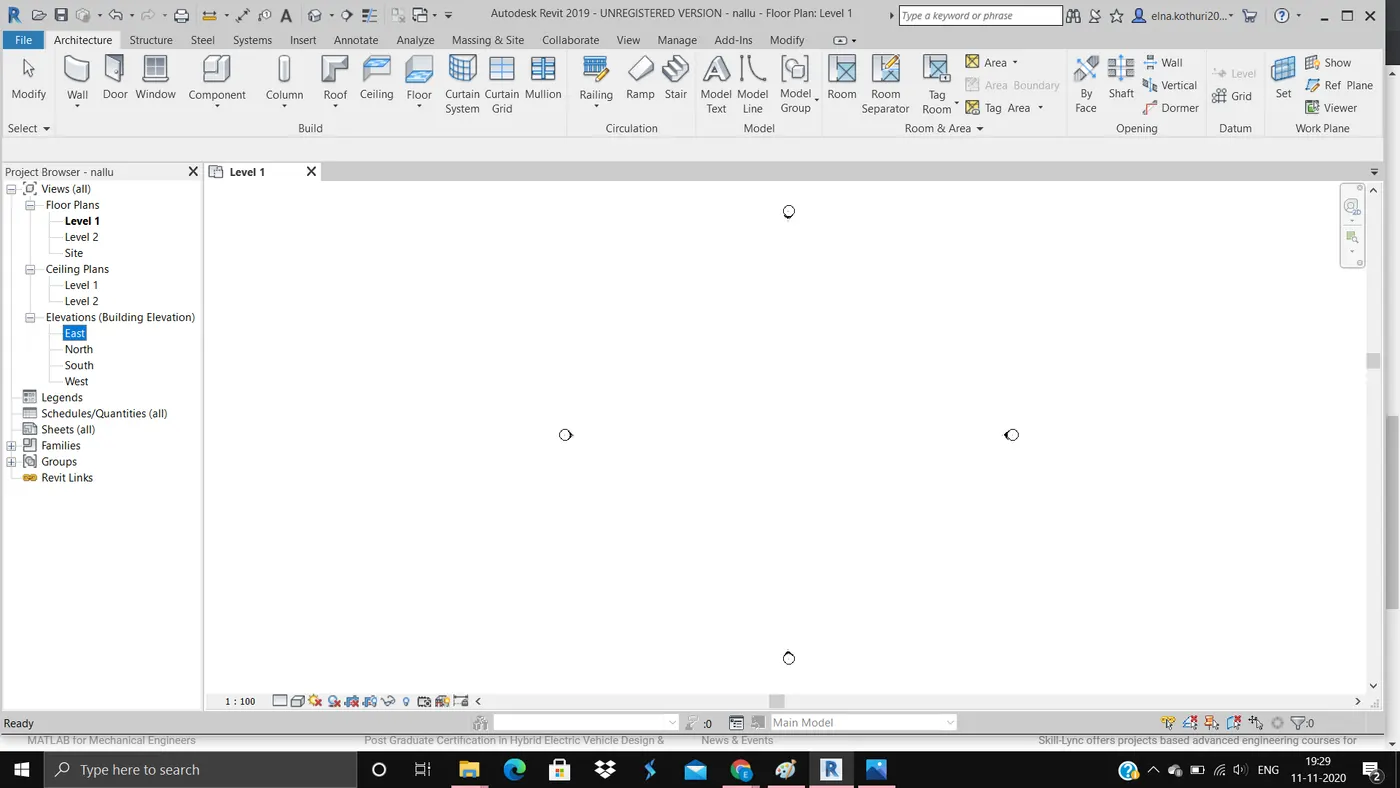
1.Firstly choose the architectural template and click on east option under the elevations.
2.After that we can see the elevation views of the levels then place them with desired distance.
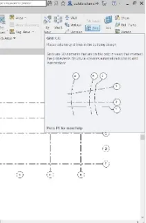
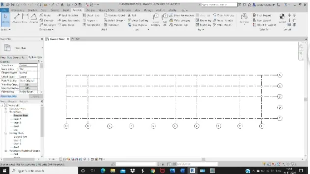
3.Then click on ground floor under floor plans and select the grid option under the architecture menu and start drawing.
4.First draw five horizontal grid lines and name them A,B,C,D and E with giving equal space of 10'
5.After that draw vertical grid lines and name them 1 to 10 giving equal space of 20'.
RESULT:
By the end of the drawing you will be able to create 1st,2nd,ground floor and roof .and also horizontal and vertical grid lines.
5.AIM:3D modelling of a residential house and creating a conceptual layout of the residential unit.
TOOLS REQUIRED:
>Architecture
>wall
>default 3D view
>view
PROCEDURE:
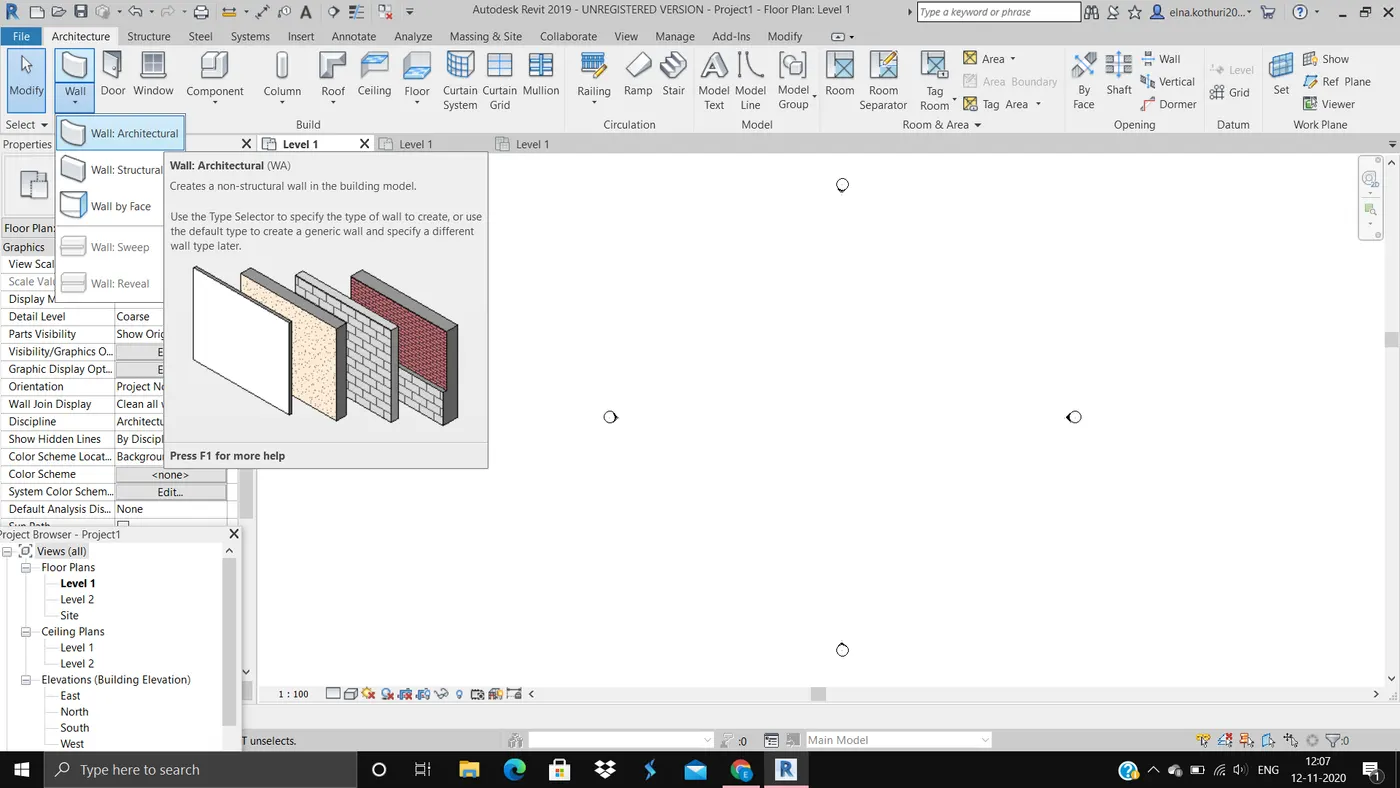
1.Firstly open the revit and choose the architectural template and click OK.
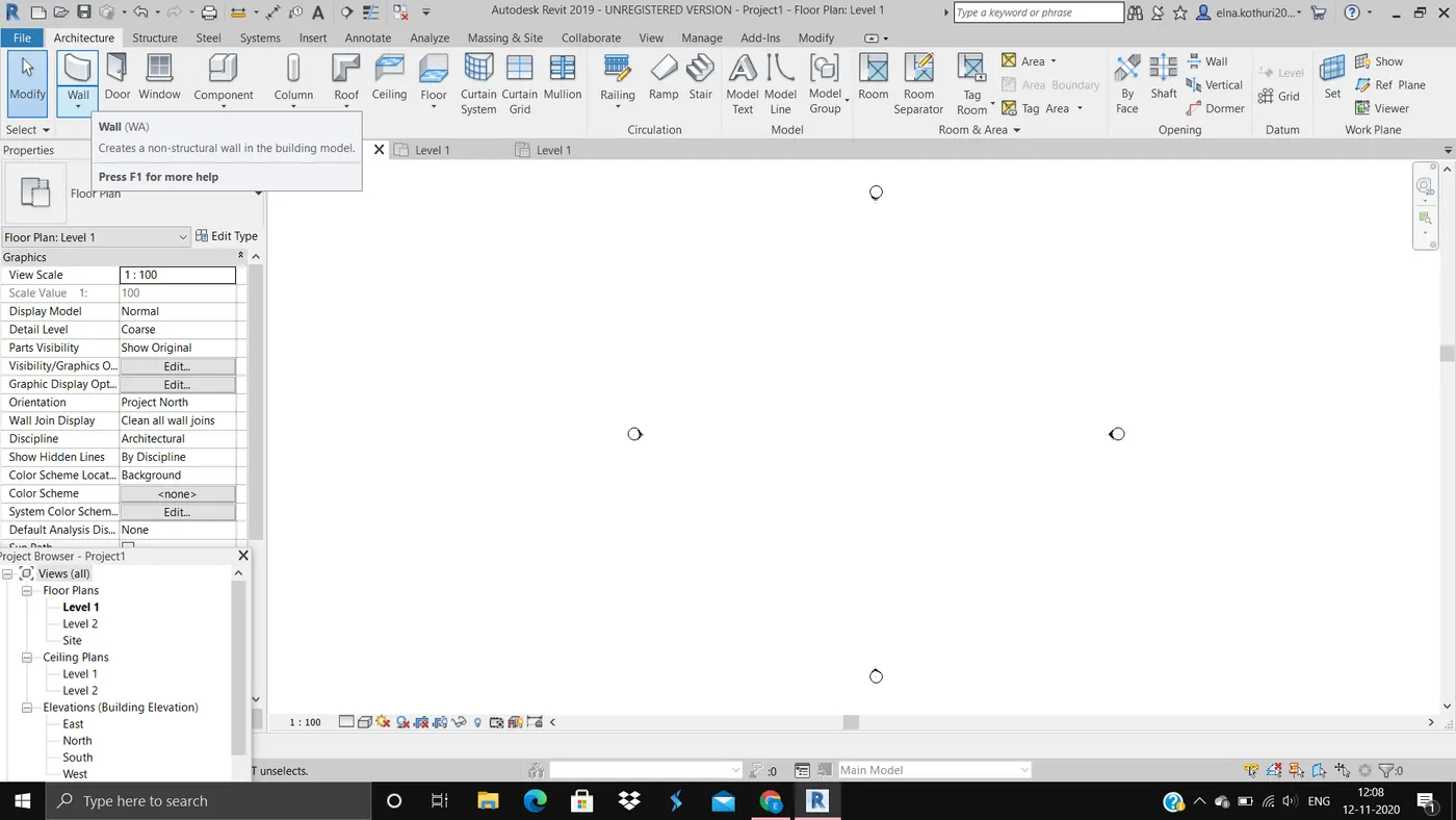
2.Select the wall tab.
3.Start drawing the desired shape of residential building with desired measurements.
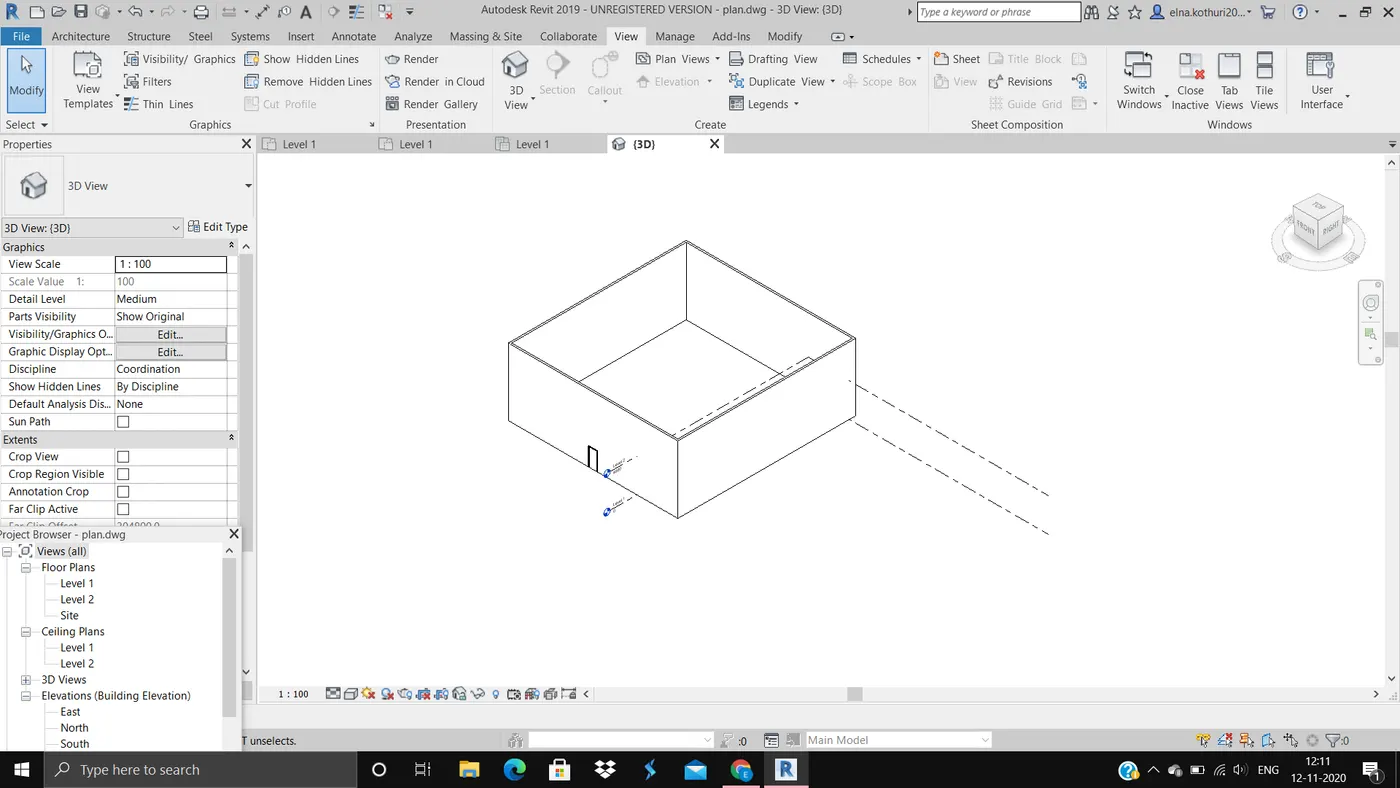
4.After finishing step 3 click on 3D view option.
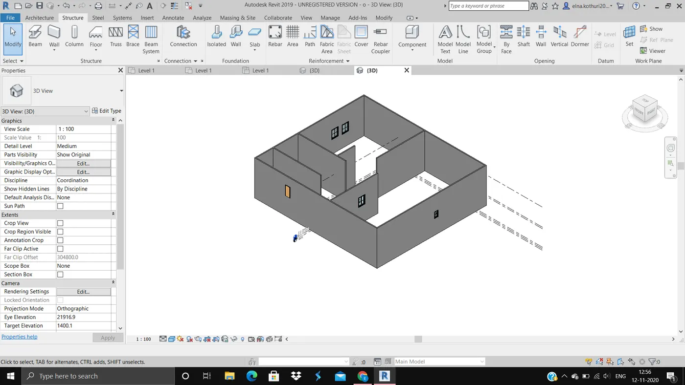
5.By clicking on the 3D view option you can see that your model appears in a 3D model.
RESULT:
By following the above procedure you can create a 3D residential building with desired dimensions.
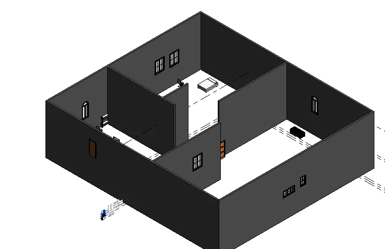
("For the better understanding consider the below pictures")
6.AIM:In the layout created thr draft level of details you are planning to include -Dimensions of the room,components to the residential building.
TOOLS REQUIRED:
>Windows and doors
>archicture
>architecture
>view
>load family
>insert
PROCEDURE:
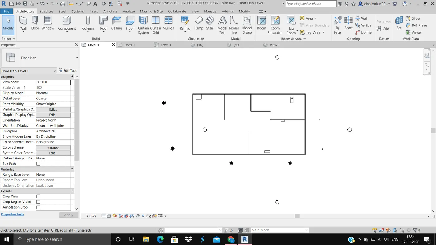
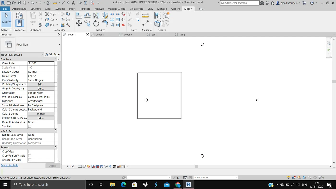
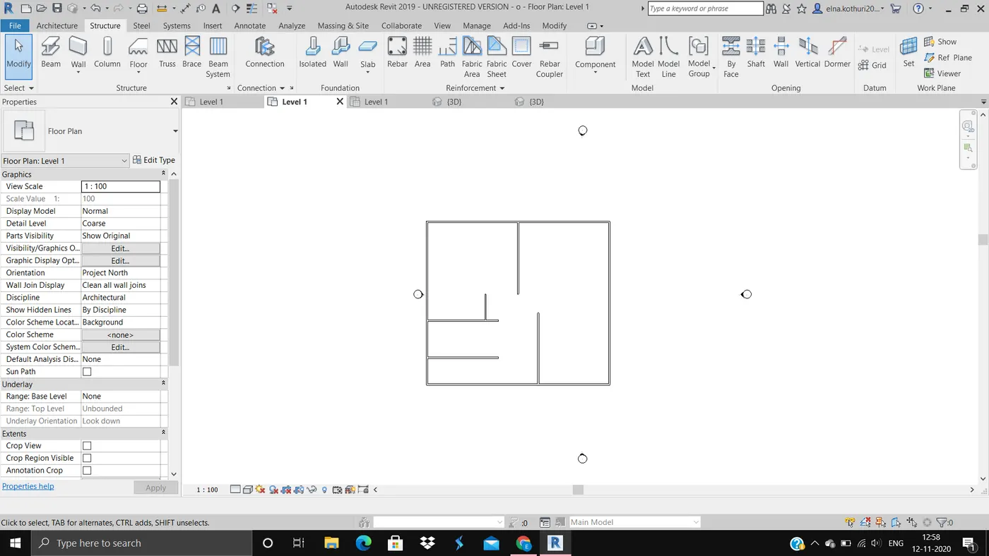
1.Open the architectural template click on the wall option.draw the walls of required dimensions in a square shape.
2.And also finish the inner walls.
3.Click on the insert tab to and tap on the load family to introdure doors, windows etc..
4.Measure the dimensions by aligned measure.
5.Click view tab in that select 3D view.
RESULT :
By following the above steps we can get Our 3D model of residential building with conceptual layout .
7.AIM:Inserting Door, Window, Tables, Chair, Couch, Bed, Lamps in the project.
TOOLS REQUIRED:
>Architecture template
>Insert
>Windows and doors
>Dining table
>Bed
PROCEDURE:
1.Open the architectural template click on the wall tool and make walls.
2.After construction of a closed model with walls make diffrent inner walls inside.
3.Now click on the insert menu and tab on the load family to introudue the doors, windows, chairs,furniture,window panels,bed etc....
4.After selecting an object in load family click ok.
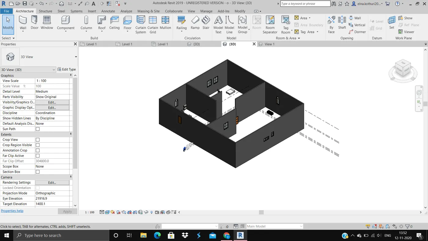
5.Now finally, go to the view tab and click on the default 3D tool.
RESULT:
Adding/inserting the load family contents i.e.,(furniture, doors, windows, chairs, lamps....)is sucessfully done in the project model.