Week 2 Challenge
1.What are workspaces and work sets? List Civil specific variables (min. 5). Where are the workspaces saved on computer (default location).
Ans: A Workspace is a place where the DOTs store their “Department Standards”, resources, libraries, and custom applications such levels, cells, line styles, feature definitions, macros (BAS/VBA/MDL), pen tables/design scripts, color table/book, unit definitions (miles/feet English vs. kilometers/meters Metric), Design Standards, seed files, etc. A Workspace is the “parent” of a Work Set.
A Work Set is the “Project” or plan set using the resources and standards of a Workspace.
Civil-specific variables:
- CIVIL_CIVILTMDGNLIBLIST
- CIVIL_DISALLOW_LOCKCHANGES
- CIVIL_CIVILSETTINGS_READONLY
- CIVIL_SHOW_SHARED_FEATUREDEF_PROPS
- CIVIL_EXAGGERATION_VALUES
- CIVIL_DEFAULTSETTINGS
- CIVIL_DEFAULT_LINEAR_STROKING
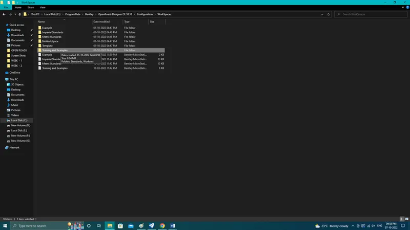
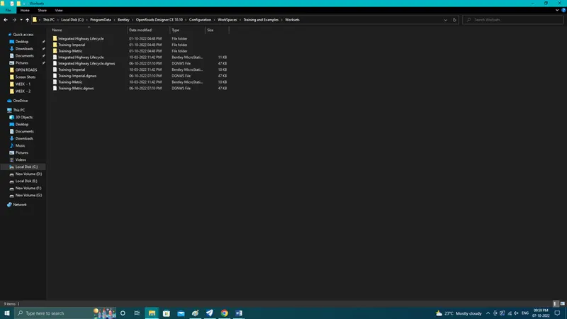
Save Location:
Workspace Folder: C:\ProgramData\Bentley\OpenRoads Designer CE 10.10\Configuration\WorkSpaces
Workset Folder: C:\ProgramData\Bentley\OpenRoads Designer CE 10.10\Configuration\WorkSpaces\Training and Examples\Worksets
2.What are feature definitions? What is broader classification of feature definition types.
Ans: A Feature Definition controls how each feature is displayed and how it interacts with various tasks. The first time you use a Feature Definition it is copied into your active DGN and can then be modified.
- Properties are used to define how a feature is to be displayed, annotated, computed, etc.
- These are normally customized by each organization.
- These are normally created in advance and propagated across an organization in order to standardize designs.
Types of Feature Definitions
3 types of feature definitions are supported depending on its type, a feature definition will have various properties that are available for definition.
Point Feature
- R/W Marker
- Control Point
- Iron Pin
Linear Feature
- Curb & Gutter
- Wall
- Ditch
Surface Feature
- Existing Ground
- Aggregate Base
- Asphalt Pavement
3.Create a dgn file with 2D imperial seed file and 3D imperial seed file. Save it in project data folder, creating new folder named DGN from SEED.
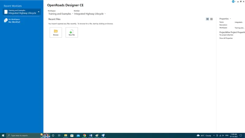
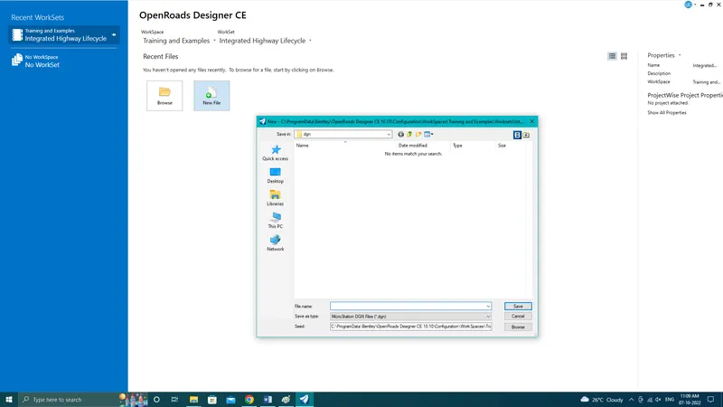
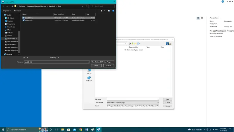
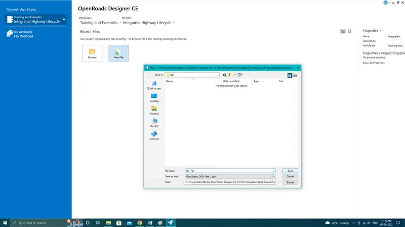
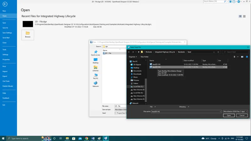
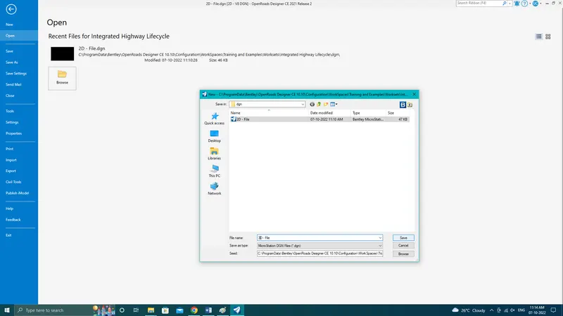
Ans: Opening Open Roads Designer - Click on New File to open a window - Click on the 'Browse Option' adjacent to the Seed file to set the seed file - Select the 2D Imperial Design Seed File and Click open - Click on save to open the DGN file with 2D Imperial Seed File
Click on New File to open a window - Click on the 'Browse Option' adjacent to the Seed file to set the seed file - Select the 3D Imperial Design Seed File and Click open - Click on save to open the DGN file with 3D Imperial Seed File
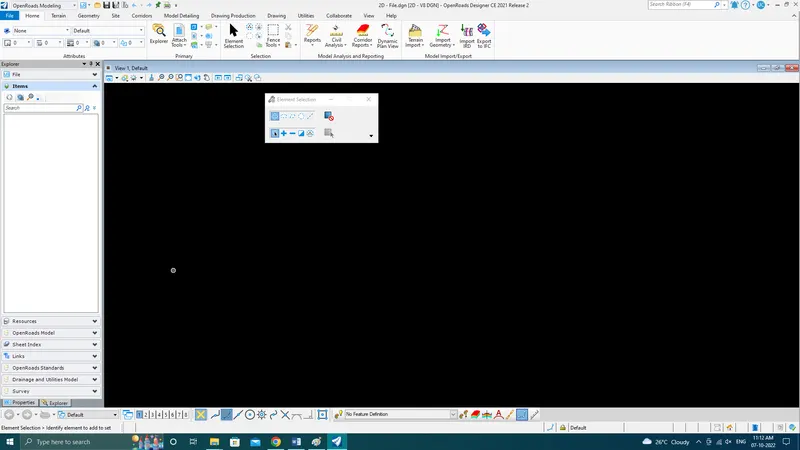
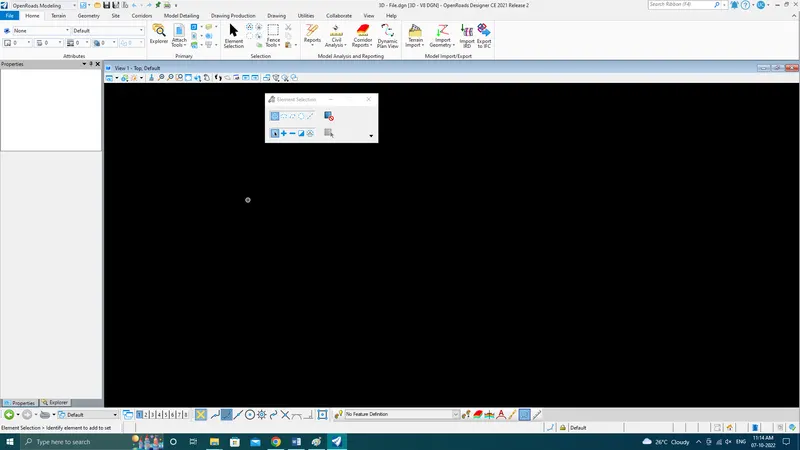
4.Set geographic coordinate system to TX-83, North Central zone, US survey foot. Turn on the background imagery. Save this file with save settings.
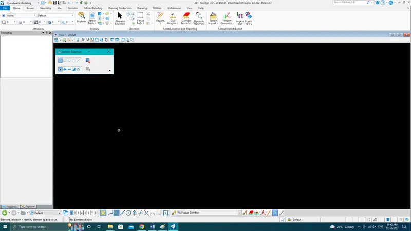
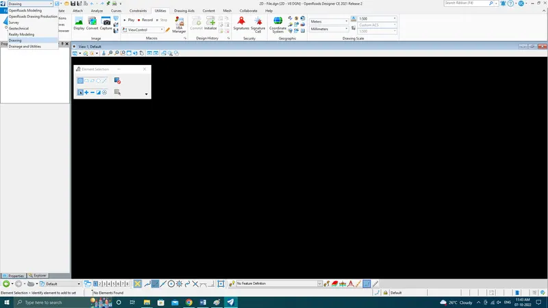
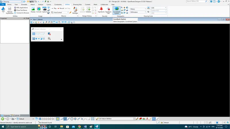
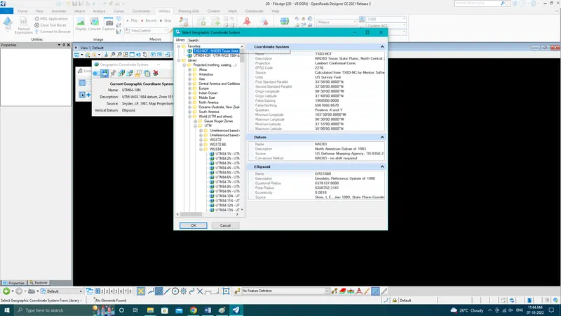
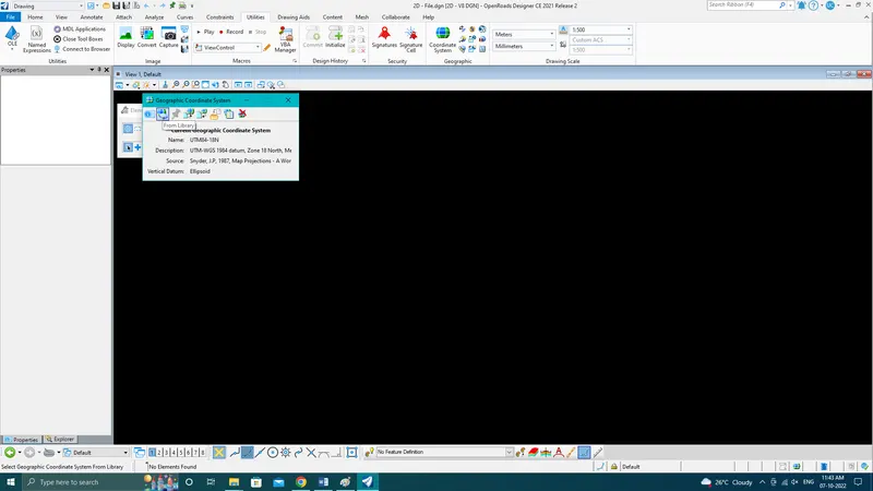
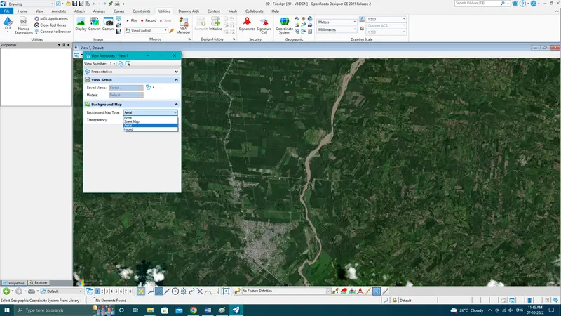
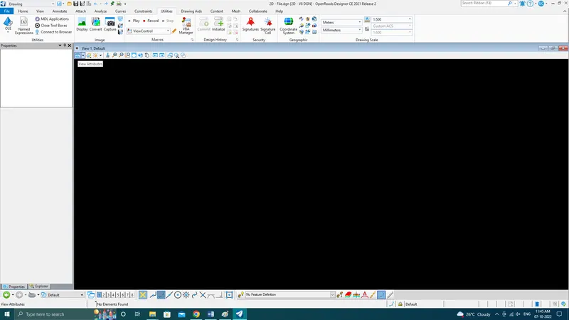
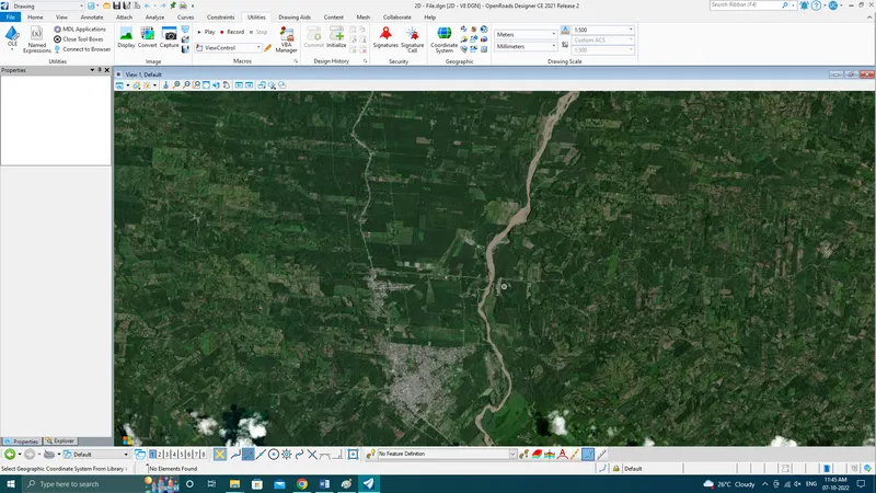
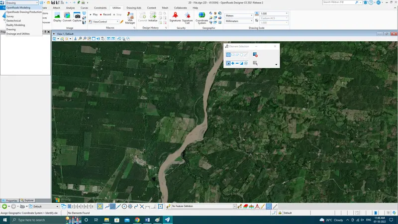
Ans: Opening Open Roads Designer - Open a new file with a 2D seed file as shown below - Go to the 'Utilities' tab - Click on the 'Coordinate system' - Click on From Library and change the coordinate system - From Popup go to the Search tab and search for TX-83, North Central zone - Click ok to set the coordinate system - Go to view attributes - Set the background map as AERIAL - After setting the coordinate system and turning on the Background imagery
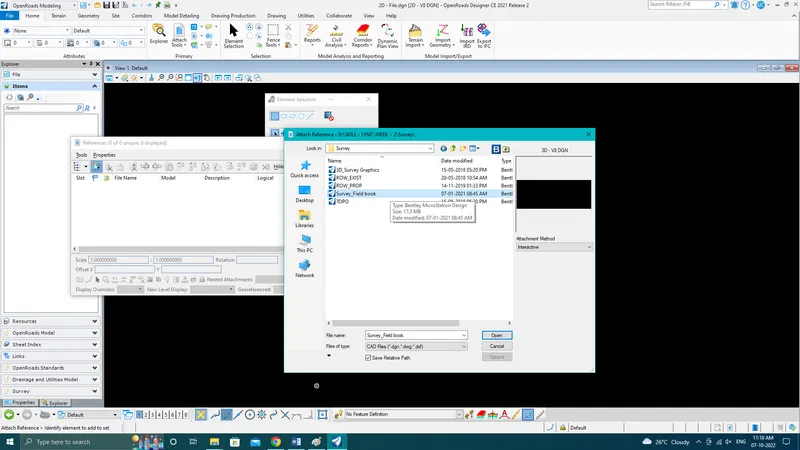
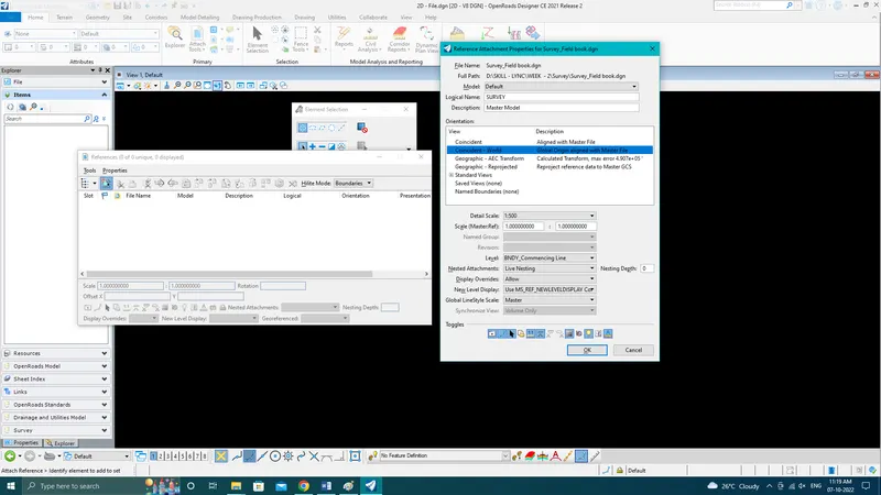
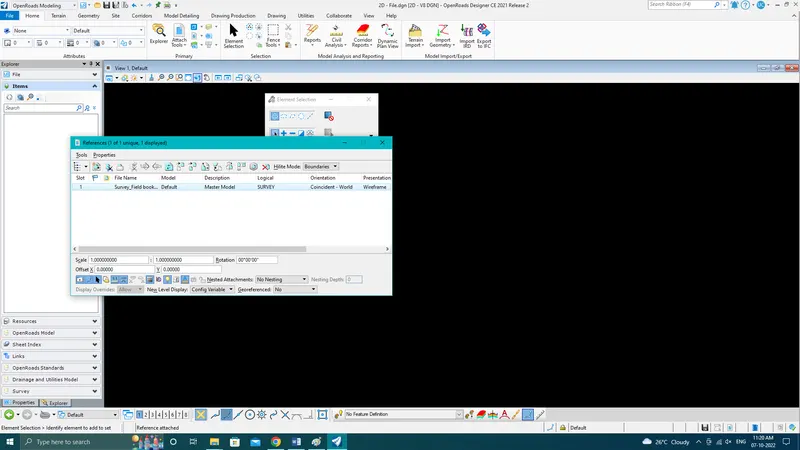
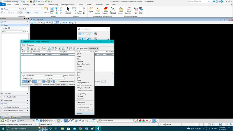
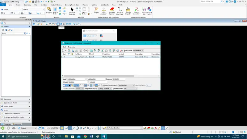
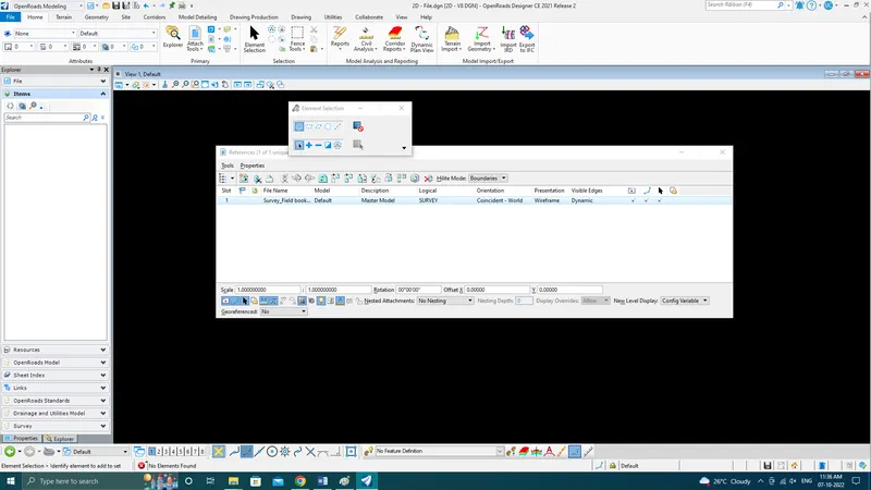
5.Attach the survey file from SURVEY folder to the newly created 2D dgn in above #3.
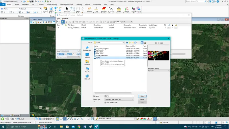
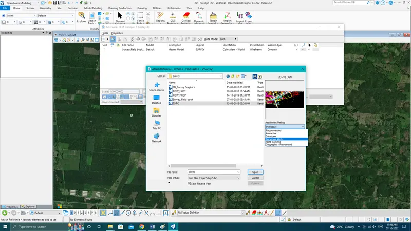
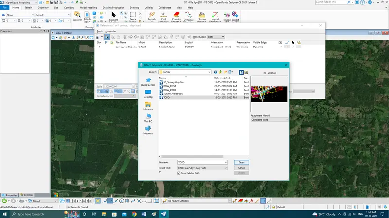
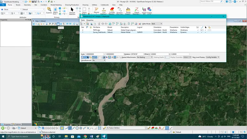
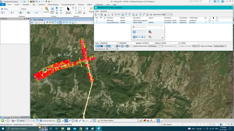
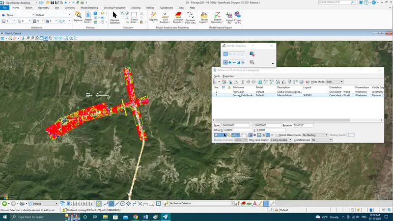
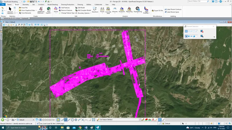
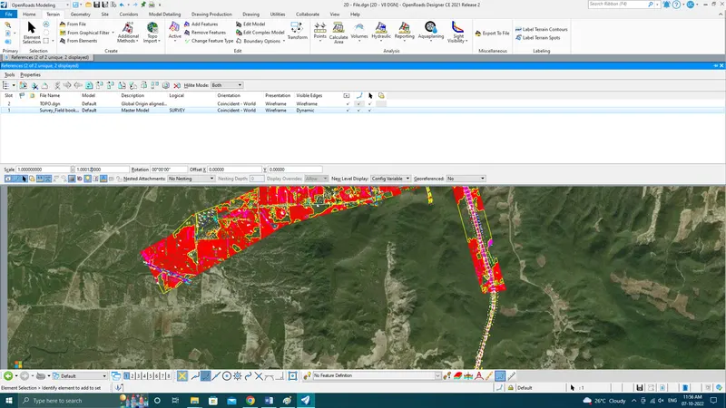
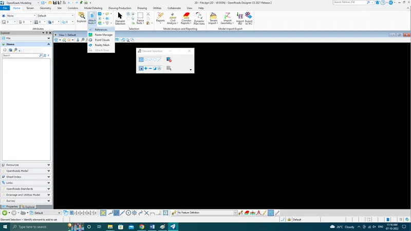
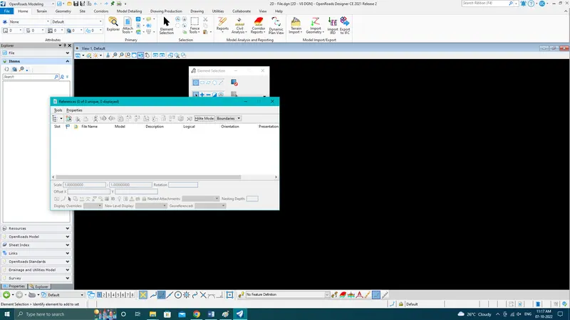
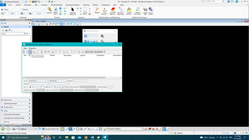
Ans: Opening Open Roads Designer - Open the file created with a 2D seed file - Opening Survey File - Go to the Primary tab and click on 'Attach Tools' - Click on References to attach the survey file - Click on 'Attach Reference' - Select the 'TOPO' file - Set Attachment method as interactive - Click open - Set the Logic name as Topo - Set Nesting as Live Nesting and set Nesting depth as 1 - Click on Fit view to fit the topo data in the screen -
\