Project 1 - Geometric Design Parameter- Prerequisites
Project 1 - Geometric Design Parameter- Prerequisites
INTRODUCTION:
The geometric design of highways deals with the dimensions and layout of visible features of the highway. The emphasis of the geometric design is to address the requirement of the driver and the vehicle such as safety, comfort, efficiency, etc. The features normally considered are the cross-section elements, sight distance consideration, horizontal curvature, gradients, and intersection. The design of these features is to a great extend influenced by driver behavior and psychology, vehicle characteristics, traffic characteristics such as speed and volume. Proper geometric design will help in the reduction of accidents and their severity. Therefore, the objective of geometric design is to provide optimum efficiency in traffic operation and maximum safety at reasonable cost.
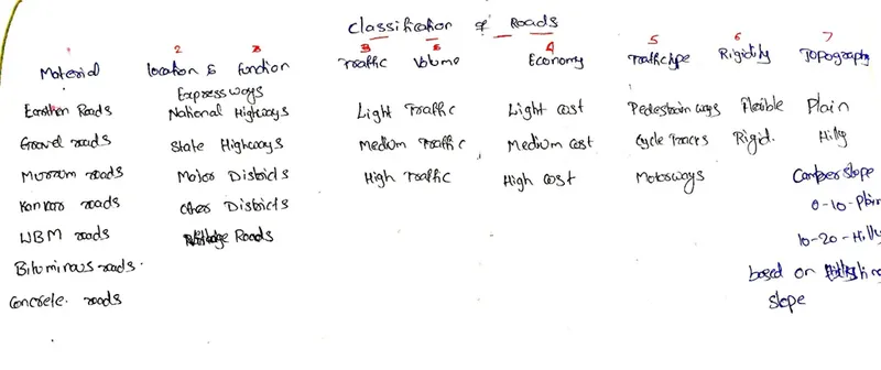
Road classification
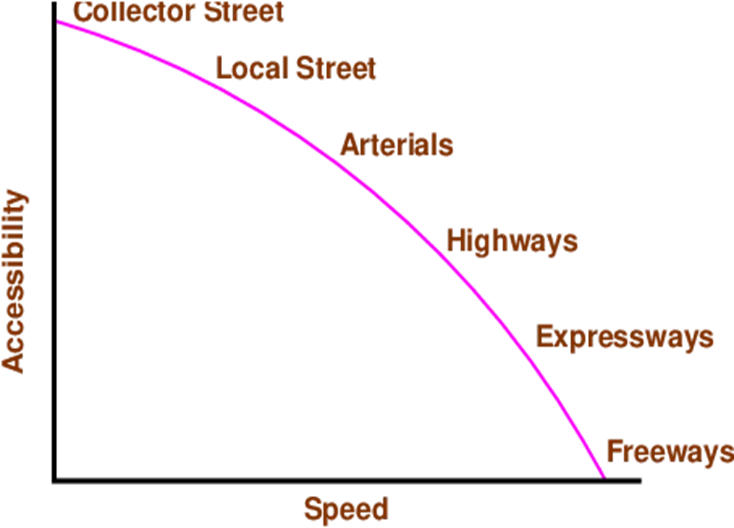
The roads can be classified in many ways. The classification based on speed and accessibility is the most generic one. Note that as the accessibility of road increases, the speed reduces. (See figure 1). Accordingly, the roads can be classified as follows in the order of increased accessibility and reduced speeds.
- Freeways: Freeways are access-controlled divided highways. Most freeways are four lanes, two lanes each direction, but many freeways widen to incorporate more lanes as they enter urban areas. Access is controlled through the use of interchanges, and the type of interchange depends upon the kind of intersecting road way (rural roads, another freeway etc.)
- Expressways: They are superior type of highways and are designed for high speeds ( 120 km/hr is common), high traffic volume and safety. They are generally provided with grade separations at intersections. Parking, loading and unloading of goods and pedestrian traffic is not allowed on expressways.
- Highways: They represent the superior type of roads in the country. Highways are of two types - rural highways and urban highways. Rural highways are those passing through rural areas (villages) and urban highways are those passing through large cities and towns, ie. urban areas.
- Arterials: It is a general term denoting a street primarily meant for through traffic usually on a continuous route. They are generally divided highways with fully or partially controlled access. Parking, loading and unloading activities are usually restricted and regulated. Pedestrians are allowed to cross only at intersections/designated pedestrian crossings.
- Local streets: A local street is the one which is primarily intended for access to residence, business or abutting property. It does not normally carry large volume of traffic and also it allows unrestricted parking and pedestrian movements.
- Collector streets: These are streets intended for collecting and distributing traffic to and from local streets and also for providing access to arterial streets. Normally full access is provided on these streets. There are few parking restrictions except during peak hours.
Factors affecting geometric design
A number of factors affect the geometric design and they are discussed in detail in the following sections.
1 Design speed
Design speed is the single most important factor that affects the geometric design. It directly affects the sight distance, horizontal curve, and the length of vertical curves. Since the speed of vehicles vary with driver, terrain etc, a design speed is adopted for all the geometric design.
Design speed is defined as the highest continuous speed at which individual vehicles can travel with safety on the highway when weather conditions are conducive. Design speed is different from the legal speed limit which is the speed limit imposed to curb a common tendency of drivers to travel beyond an accepted safe speed. Design speed is also different from the desired speed which is the maximum speed at which a driver would travel when unconstrained by either traffic or local geometry.
Since there are wide variations in the speed adopted by different drivers, and by different types of vehicles, design speed should be selected such that it satisfies nearly all drivers. At the same time, a higher design speed has cascading effect in other geometric designs and thereby cost escalation. Therefore, an 85th percentile design speed is normally adopted. This speed is defined as that speed which is greater than the speed of 85% of drivers. In some countries this is as high as 95 to 98 percentile speed.
2 Topography
The next important factor that affects the geometric design is the topography. It is easier to construct roads with required standards for a plain terrain. However, for a given design speed, the construction cost increases multiform with the gradient and the terrain. Therefore, geometric design standards are different for different terrain to keep the cost of construction and time of construction under control. This is characterized by sharper curves and steeper gradients.
3 Other factors
In addition to design speed and topography, there are various other factors that affect the geometric design and they are briefly discussed below:
4.Vehicle: The dimensions, weight of the axle and operating characteristics of a vehicle influence the design aspects such as width of the pavement, radii of the curve, clearances, parking geometrics etc. A design vehicle which has standard weight, dimensions and operating characteristics are used to establish highway design controls to accommodate vehicles of a designated type.
5.Human: The important human factors that influence geometric design are the physical, mental and psychological characteristics of the driver and pedestrians like the reaction time.
6.Traffic: It will be uneconomical to design the road for peak traffic flow. Therefore, a reasonable value of traffic volume is selected as the design hourly volume which is determined from the various traffic data collected. The geometric design is thus based on this design volume, capacity etc.
7.Environmental: Factors like air pollution, noise pollution etc. should be given due consideration in the geometric design of roads.
8.Economy: The design adopted should be economical as far as possible. It should match with the funds allotted for capital cost and maintenance cost.
9.Others: Geometric design should be such that the aesthetics of the region is not affected.
Highway alignment
Once the necessity of the highway is assessed, the next process is deciding the alignment. The highway alignment can be either horizontal or vertical.
Alignment
The position or the layout of the central line of the highway on the ground is called the alignment. Horizontal alignment includes straight and curved paths. Vertical alignment includes level and gradients. Alignment decision is important because a bad alignment will enhance the construction, maintenance and vehicle operating costs. Once an alignment is fixed and constructed, it is not easy to change it due to increase in cost of adjoining land and construction of costly structures by the roadside.
vertical alignment:
The vertical alignment of highway generally defined as the presence of heights and depths in vertical axis with respect to horizontal axis of alignment. These heights and depths in roads may be in the form of gradients (straight lines in a vertical plane) or vertical curves.
cross section:
In the cross section of roads, it is that portion of the roadway between the outer edge of the outer traffic lane and the inside edge of the ditch, gutter, curb or slope. Shoulders are provided for the safe operation and to allow the development of full traffic capacity.
Requirements
The requirements of an ideal alignment are
- The alignment between two terminal stations should be short and as far as possible be straight, but due to some practical consideration’s deviations may be needed.
- The alignment should be easy to construct and maintain. It should be easy for the operation of vehicles. So, to the maximum extend easy gradients and curves should be provided.
- It should be safe both from the construction and operating point of view especially at slopes, embankments, and cutting. It should have safe geometric features.
- The alignment should be economical and it can be considered so only when the initial cost, maintenance cost, and operating cost are minimum.
Factors controlling alignment
We have seen the requirements of an alignment. But it is not always possible to satisfy all these requirements. Hence, we have to make a judicial choice considering all the factors.
The various factors that control the alignment are as follows:
- Obligatory points: These are the control points governing the highway alignment. These points are classified into two categories. Points through which it should pass and points through which it should not pass. Some of the examples are:
- bridge site: The bridge can be located only where the river has straight and permanent path and also where the abutment and pier can be strongly founded. The road approach to the bridge should not be curved and skew crossing should be avoided as possible. Thus, to locate a bridge the highway alignment may be changed.
- mountain: While the alignment passes through a mountain, the various alternatives are to either construct a tunnel or to go round the hills. The suitability of the alternative depends on factors like topography, site conditions and construction and operation cost.
- intermediate town: The alignment may be slightly deviated to connect an intermediate town or village nearby.
These were some of the obligatory points through which the alignment should pass. Coming to the second category, that is the points through which the alignment should not pass are:
- religious places: These have been protected by the law from being acquired for any purpose. Therefore, these points should be avoided while aligning.
- very costly structures: Acquiring such structures means heavy compensation which would result in an increase in initial cost. So, the alignment may be deviated not to pass through that point.
- lakes/ponds etc: The presence of a lake or pond on the alignment path would also necessitate deviation of the alignment.
- Traffic: The alignment should suit the traffic requirements. Based on the origin-destination data of the area, the desire lines should be drawn. The new alignment should be drawn keeping in view the desire lines, traffic flow pattern etc.
- Geometric design: Geometric design factors such as gradient, radius of curve, sight distance etc. also governs the alignment of the highway. To keep the radius of curve minimum, it may be required to change the alignment. The alignments should be finalized such that the obstructions to visibility do not restrict the minimum requirements of sight distance. The design standards vary with the class of road and the terrain and accordingly the highway should be aligned.
- Economy: The alignment finalized should be economical. All the three costs i.e. construction, maintenance, and operating cost should be minimum. The construction cost can be decreased much if it is possible to maintain a balance between cutting and filling. Also try to avoid very high embankments and very deep cuttings as the construction cost will be very higher in these cases.
- Other considerations: various other factors that govern the alignment are drainage considerations, political factors and monotony.
- Drainage:
- Political: If a foreign territory comes across a straight alignment, we will have to deviate the alignment around the foreign land.
- Monotony: For a flat terrain it is possible to provide a straight alignment, but it will be monotonous for driving. Hence a slight bend may be provided after a few kilometers of straight road to keep the driver alert by breaking the monotony.
- Hydrological (rainfall/water table): The pavement should be as high above the water table as possible, so that saturation/submergence and subsequent damage to subgrade are avoided.
Cross Sectional Elements:
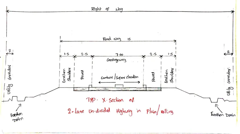
The features of the cross-section of the pavement influences the life of the pavement as well as the riding comfort and safety. Of these, pavement surface characteristics affect both of these. Camber,kerbs, and geometry of various cross-sectional elements are important aspects to be considered in this regard.
Pavement surface characteristics
For safe and comfortable driving four aspects of the pavement surface are important; the friction between the wheels and the pavement surface, smoothness of the road surface, the light reflection characteristics of the top of pavement surface, and drainage to water.
Friction
Friction between the wheel and the pavement surface is a crucial factor in the design of horizontal curves and thus the safe operating speed. Further, it also affects the acceleration and deceleration ability of vehicles. Lack of adequate friction can cause skidding or slipping of vehicles.
Skidding happens when the path traveled along the road surface is more than the circumferential movement of the wheels due to friction Slip occurs when the wheel revolves more than the corresponding longitudinal movement along the road.Various factors that affect friction are:
Type of the pavement (like bituminous, concrete, or gravel),
Condition of the pavement (dry or wet, hot or cold, etc),
Condition of the tyre (new or old), and Speed and load of the vehicle.
The frictional force that develops between the wheel and the pavement is the load acting multiplied by a factor called the coefficient of friction and denoted as f. The choice of the value of f is a very complicated issue since it depends on many variables. IRC suggests the coefficient of longitudinal friction as 0.35-0.4 depending on the speed and coefficient of lateral friction as 0.15. The former is useful in sight distance calculation and the latter in horizontal curve design.
Unevenness
It is always desirable to have an even surface, but it is seldom possible to have such a one. Even if a road is constructed with high quality pavers, it is possible to develop unevenness due to pavement failures. Unevenness affects the vehicle operating cost, speed, riding comfort, safety, fuel consumption and wear and tear of tyres.
Unevenness index is a measure of unevenness which is the cumulative measure of vertical undulations of the pavement surface recorded per unit horizontal length of the road. An unevenness index value less than 1500 mm/km is considered as good, a value less than 2500 mm.km is satisfactory up to speed of 100 kmph and values greater than 3200 mm/km is considered as uncomfortable even for 55 kmph.
Light reflection
- White roads have good visibility at night, but caused glare during day time.
- Black roads have no glare during day, but has poor visibility at night
- Concrete roads have better visibility and less glare
It is necessary that the road surface should be visible at night and reflection of light is the factor that answers it.
Drainage
The pavement surface should be absolutely impermeable to prevent seepage of water into the pavement layers. Further, both the geometry and texture of pavement surface should help in draining out the water from the surface in less time.
Camber
Camber or cant is the cross slope provided to raise middle of the road surface in the transverse direction to drain off rain water from road surface. The objectives of providing camber are:
- Surface protection especially for gravel and bituminous roads
- Sub-grade protection by proper drainage
- Quick drying of pavement which in turn increases safety
Width of carriage way
Width of the carriage way or the width of the pavement depends on the width of the traffic lane and number of lanes. Width of a traffic lane depends on the width of the vehicle and the clearance. Side clearance improves operating speed and safety. The maximum permissible width of a vehicle is 2.44 and the desirable side clearance for single lane traffic is 0.68 m. This requires minimum of lane width of 3.75 m for a single lane road.
Kerbs
Kerbs indicates the boundary between the carriage way and the shoulder or islands or footpaths
Road margins
The portion of the road beyond the carriageway and on the roadway can be generally called road margin. Various elements that form the road margins are given below.
Shoulders
Shoulders are provided along the road edge and is intended for accommodation of stopped vehicles, serve as an emergency lane for vehicles and provide lateral support for base and surface courses. The shoulder should be strong enough to bear the weight of a fully loaded truck even in wet conditions. The shoulder width should be adequate for giving working space around a stopped vehicle. It is desirable to have a width of 4.6 m for the shoulders. A minimum width of 2.5 m is recommended for 2-lane rural highways in India.
Parking lanes
Parking lanes are provided in urban lanes for side parking. Parallel parking is preferred because it is safe for the vehicles moving on the road. The parking lane should have a minimum of 3.0 m width in the case of parallel parking.
Bus-bays
Bus bays are provided by recessing the kerbs for bus stops. They are provided so that they do not obstruct the movement of vehicles in the carriage way. They should be at least 75 meters away from the intersection so that the traffic near the intersections is not affected by the bus-bay.
Service roads
Service roads or frontage roads give access to access-controlled highways like freeways and expressways. They run parallel to the highway and will be usually isolated by a separator and access to the highway will be provided only at selected points. These roads are provided to avoid congestion in the expressways and also the speed of the traffic in those lanes is not reduced.
Cycle track
Cycle tracks are provided in urban areas when the volume of cycle traffic is high Minimum width of 2 meter is required, which may be increased by 1 meter for every additional track.
Footpath
Footpaths are exclusive right of way to pedestrians, especially in urban areas. They are provided for the safety of the pedestrians when both the pedestrian traffic and vehicular traffic is high. Minimum width is 1.5 meter and may be increased based on the traffic. The footpath should be either as smooth as the pavement or more smoother than that to induce the pedestrian to use the footpath.
Guard rails
They are provided at the edge of the shoulder usually when the road is on an embankment. They serve to prevent the vehicles from running off the embankment, especially when the height of the fill exceeds 3 m. Various designs of guard rails are there. Guard stones painted in alternate black and white are usually used. They also give better visibility of curves at night under headlights of vehicles.
Width of formation
Width of formation or roadway width is the sum of the widths of pavements or carriage way including separators and shoulders. This does not include the extra land in formation/cutting.
Right of way
Right of way (ROW) or land width is the width of land acquired for the road, along its alignment. It should be adequate to accommodate all the cross-sectional elements of the highway and may reasonably provide for future development. To prevent ribbon development along highways, control lines and building lines may be provided. Control line is a line which represents the nearest limits of future uncontrolled building activity in relation to a road. Building line represents a line on either side of the road, between which and the road no building activity is permitted at all. The right of way width is governed by:
- Width of formation: It depends on the category of the highway and width of roadway and road margins.
- Height of embankment or depth of cutting: It is governed by the topography and the vertical alignment.
- Side slopes of embankment or cutting: It depends on the height of the slope, soil type etc.
- Drainage system and their size which depends on rainfall, topography etc.
- Sight distance considerations: On curves etc., there is restriction to the visibility on the inner side of the curve due to the presence of some obstructions like building structures etc.
- Reserve land for future widening: Some land has to be acquired in advance anticipating future developments like widening of the road.
Sight Distances:
The safe and efficient operation of vehicles on the road depends very much on the visibility of the road ahead of the driver. Thus, the geometric design of the road should be done such that any obstruction on the road length could be visible to the driver from some distance ahead. This distance is said to be the sight distance.
Types of sight distance
Sight distance available from a point is the actual distance along the road surface, over which a driver from a specified height above the carriage way has visibility of stationary or moving objects. Three sight distance situations are considered for design:
- Stopping sight distance (SSD) or the absolute minimum sight distance
- Intermediate sight distance (ISD) is defined as twice SSD
- Overtaking sight distance (OSD) for safe overtaking operation
- Head light sight distance is the distance visible to a driver during night driving under the illumination of head lights
- Safe sight distance to enter into an intersection.
The most important consideration in all these is that at all times the driver traveling at the design speed of the highway must have sufficient carriageway distance within his line of vision to allow him to stop his vehicle before colliding with a slowly moving or stationary object appearing suddenly in his own traffic lane.
The computation of sight distance depends on:
- Reaction time of the driver
Reaction time of a driver is the time taken from the instant the object is visible to the driver to the instant when the brakes are applied. The total reaction time may be split up into four components based on PIEV theory. In practice, all these times are usually combined into a total perception-reaction time suitable for design purposes as well as for easy measurement. Many of the studies shows that drivers require about 1.5 to 2 secs under normal conditions. However, taking into consideration the variability of driver characteristics, a higher value is normally used in design. For example, IRC suggests a reaction time of 2.5 secs.
- Speed of the vehicle
The speed of the vehicle very much affects the sight distance. Higher the speed, more time will be required to stop the vehicle. Hence it is evident that, as the speed increases, sight distance also increases.
- Efficiency of brakes
The efficiency of the brakes depends upon the age of the vehicle, vehicle characteristics etc. If the brake efficiency is 100%, the vehicle will stop the moment the brakes are applied. But practically, it is not possible to achieve 100% brake efficiency. Therefore, the sight distance required will be more when the efficiency of brakes is less. Also, for safe geometric design, we assume that the vehicles have only 50% brake efficiency.
- Frictional resistance between the tyre and the road
The frictional resistance between the tyre and road plays an important role to bring the vehicle to stop. When the frictional resistance is more, the vehicles stop immediately. Thus, sight required will be less. No separate provision for brake efficiency is provided while computing the sight distance. This is taken into account along with the factor of longitudinal friction. IRC has specified the value of longitudinal friction in between 0.35 to 0.4.
- Gradient of the road.
Gradient of the road also affects the sight distance. While climbing up a gradient, the vehicle can stop immediately. Therefore, sight distance required is less. While descending a gradient, gravity also comes into action and more time will be required to stop the vehicle. Sight distance required will be more in this case.
Stopping sight distance:
Stopping sight distance (SSD) is the minimum sight distance available on a highway at any spot having sufficient length to enable the driver to stop a vehicle traveling at design speed, safely without collision with any other obstruction.
There is a term called safe stopping distance and is one of the important measures in traffic engineering. It is the distance a vehicle travels from the point at which a situation is first perceived to the time the deceleration is complete. Drivers must have adequate time if they are to suddenly respond to a situation. Thus, in highway design, sight distance at least equal to the safe stopping distance should be provided. The stopping sight distance is the sum of lag distance and the braking distance. Lag distance is the distance the vehicle traveled during the reaction time t and is given by vt, where v is the velocity in m∕sec2. Braking distance is the distance traveled by the vehicle during braking operation. For a level road this is obtained by equating the work done in stopping the vehicle and the kinetic energy of the vehicle. If F is the maximum frictional force developed and the braking distance is l, then work done against friction in stopping the vehicle is Fl = fWl where W is the total weight of the vehicle.
Therefore, the SSD = lag distance + braking distance and given by:
SSD = Vt + V2/2gf (when V in m/sec).
where v is the design speed in m∕sec2, t is the reaction time in sec, g is the acceleration due to gravity and f is the coefficient of friction. The coefficient of friction f is given below for various design speed.
2.Intermediate sight distance (ISD) is defined as twice SSD
One definition for this is:
“A distance equivalent to twice the stopping sight distance, a distance where overtaking could be attempted with reasonable safety”
ISD is usually twice the stopping sight distance.
ISD = 2 X SSD
3.Overtaking sight distance:
The overtaking sight distance is the minimum distance open to the vision of the driver of a vehicle intending to overtake the slow vehicle ahead safely against the traffic in the opposite direction. The overtaking sight distance or passing sight distance is measured along the center line of the road over which a driver with his eye level 1.2 m above the road surface can see the top of an object 1.2 m above the road surface.
The factors that affect the OSD are:
- Velocities of the overtaking vehicle, overtaken vehicle and of the vehicle coming in the opposite direction.
- Spacing between vehicles, which in-turn depends on the speed
- Skill and reaction time of the driver
- Rate of acceleration of overtaking vehicle
- Gradient of the road
the overtaking sight distance consists of three parts.
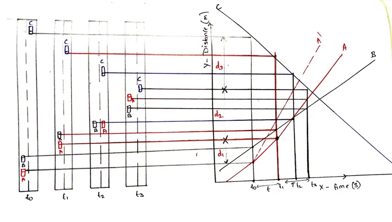
d1 the distance traveled by overtaking vehicle A during the reaction time t = t1 - t0
d2 the distance traveled by the vehicle during the actual overtaking operation T = t3-t1
d3 is the distance traveled by on-coming vehicle C during the overtaking operation (T).
Therefore: OSD = d1 + d2 + d3
It is assumed that the vehicle A is forced to reduce its speed to vb, the speed of the slow-moving vehicle B and travels behind it during the reaction time t of the driver. So d1 is given by:
Assumptions in Calculating Overtaking Sight Distance
- Vehicle A is forced to reduce the speed to that of the vehicle being overtaken (vb) and moves behind it allowing space 's' till there is an opportunity to overtake.
Therefore, d1 = vb * t
- From position a2, vehicle A accelerates, moves to the adjacent lane, overtakes and joins the lane at a distance 's' from the overtaken vehicle in time 'T'
d2 = 2*s + b, where, s - minimum spacing between the vehicles
s = (0.7*vb + 6), in m
b = vb*T, in m
The time 'T' depends on the speed of the overtaken vehicle and the acceleration of the overtaking vehicle. This can be found by equating d2 to equations of motion, vbT + 0.5*a*T^2, where a is the acceleration of vehicle 'A' in m/sec^2
d2 = b + 2s = vbT + 0.5*a*T^2, where, b = vb*T,
Therefore, 2s = 0.5*a*T^2
T = (4s/a)^0.5
- Distance moved from c1 to c3 is the distance moved by vehicle 'C' at design speed 'v m/s' in time 'T'
d3 = v*T, in m
Thus, the overtaking sight distance is given as,
OSD = d1 + d2 + d3 = vb*t + vb*T + 2*s + v*T
4.Head light sight distance is the distance visible to a driver during night driving under the illumination of head lights
It is the distance of the road available under the illumination of head lights of vehicles during night time driving.
H.S.D = S.S.D
- Safe sight distance to enter into an intersection
At intersections where two or more roads meet, visibility should be provided for the drivers approaching the intersection from either side. They should be able to perceive a hazard and stop the vehicle if required. Stopping sight distance for each road can be computed from the design speed. The sight distance should be provided such that the drivers on either side should be able to see each other
Design of sight distance at intersections may be used on three possible conditions:
- Enabling approaching vehicle to change the speed
- Enabling approaching vehicle to stop
- Enabling stopped vehicle to cross a main road.