Week 2:- BiW Fixture Basics Challenge
- What is the process of project execution activity?
Project activity means the steps that involve starting the project and the requirements in the project till up to complete the project. that includes customer requirements.
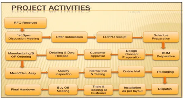
Figure-1 Process Activity
- The above image shows the process involves in process executing activities
- In general, activities which are involved in BIW fixture & Tooling
- It starts with basic requirements /RFQ we receive from the customer
- It is the starting stage of every project.
- As shown in the figure there are various steps involves in the project activities explained below
RFQ-Request For Quotation
RFQ means where the customer gives the requirement/specification in detail for the project in the form of data or document or to work on the information. also, the customer specifies its technical offer, commercial. etc how the project will be executed the timeline of the project also be mentioned in the RFQ
FIRST SPEC.DISCUSSION MEETING
- After RFQ is received, technical offer, commercial offer, TimeLine of project, etc will be discussed and prepared.
- The time required for 3D design, analysis of design, drawing &detailing, manufacturing, assembly & commission will be discussed and prepared in the technical offer
- Based on the technical offer, a commercial offer will be finalized
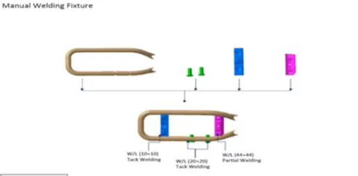
A figure-2 Basic example of a manual fixture
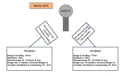
Figure-3 Technical offer for Design & manufacturing of a robotic cell
OFFER SUBMISSION
After finalization in the meeting, the offer will be submitted to the customer end. Then customer will get try to get the other quotations from the different suppliers. based on the technic, cost, quality, standard, and name in the industry the customer will finalizing the offer.
PO/LOI RECEIPT
After an offer has been finalized customer will be releasing the LOI/PO(purchase order). once PO is released we have to start the work. and then we have to prepare the schedule.
SCHEDULE PREPARATION
- In the project each activity depends on the previous activity. so if the previous activity has not been completed on time it will cause a delay in the next activity date is fixed so that it will move according to the date has already fixed on the schedule preparation.
- Schedule preparation is nothing but dividing the different activities like kick-off meeting, design data study, DAP, simulation quality check.2D detailing, Drawing check, Release of BOM, manufacturing, Brought outs of electric &mechanical components, Assembly of fixtures, Plant, Trial run out, installation and commissioning at the customer end, etc.
- Those activities will be traced in the schedule preparation chat
- The date wise schedule should be matching the committed date, otherwise have to revise the schedule and prepare accordingly in the meetings
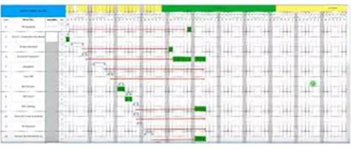
Figure-4 example of schedule chart preparation
BOM PREPARATION
- Bom preparation is listing down parts which include bought-out parts, vendor parts, and consumable items with a quantity of each of them. though Bom preparation material budget will be fixed. B/O parts include motor, gearbox, cylinder, etc. also vendor parts include all machined, fabricated parts, etc. where’s as consumables include ole, grease, glue, Loctite, etc.
DESIGN CONCEPT PREPARATION
- Before the design concept, we have to study the data of consumer requirements thoroughly which is carried out in design data study activities. during the data study, we will be prepared with rough sketches to get a flow while designing concepts
- The concept preparation would include the process like load act on panel, clamping process, which the spot should be welded first, travel of the gun. and it should conceptualize the bae date like spot plan, cycle time, etc.
- The weld gun should not collapse while traveling, by considering this has to make concept preparation. And to avoid collapses of weld guns or robots during traveling, a spot plan will be done at the initial stage
- In design concept preparation, the design of the layout are been prepared at a very initial level which gives the information of placements of robots and fixtures.
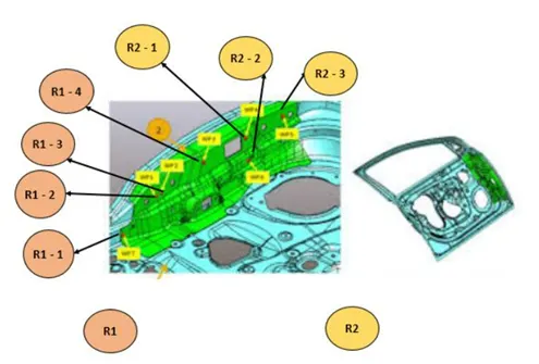
Figure-5 Spot plan
CUSTOMER APPROVAL
- It is also known as design approval process (DAP)or customer approval process in that customer will check that all his specifications consider or not in specifications, whether it is as per technical offer submitted only or not
- If the design needs to be made sample or some other corrections need to be done in concept design will be discussed and after meeting the requirement of the customer they will approve the design to go on with future activities
DETAILING &DRAWING RELEASE
- Once the customer approved the process, the detailing of the fixture pare which is to be manufactured has been done with giving appropriate dimensions and GD&T symbols.
- All the dimensions which are necessary for manufacturing should be included with GD&T in the drawings before releasing the drawing to the manufacturing team.
MANUFACTURING /BOP ORDERING
- The mechanical & Electrical parts like seniors, cylinders, etc, which need fixtures are ordered as per design specifications.
MECHANICAL / ELECTRICAL ASSEMBLY:
- After the material ordered is received to our end the quality will check the working conditions and technical specs. which meets our requirements. After the quality check, the mechanical & the electrical parts are assembled as per design
QUALITY INSPECTION:
- After the assembly again the quality check is done. In this all dimensions positional accuracy. coordinates are checked using CMM.
INTERNAL TRIAL
- After GC checks internal trials are made to check the operation of the fixture.
- It is a first trial taken in-house. So we will see by putting the assembly in the fixture whether the seating of assembly/panel suited correctly, whether the clamping operation is done properly, also whether the pins are getting into the holes. etc...
ONLINE TRIAL
- The trial will be done automatically made through a control panel. The process sequence of operations is checked as by the designed way.
PACKAGING
- To avoid damage occur in fixtures while transportation which may also lead to affect the Aesthetic look & proper function of fixture packaging has been done
- After the trials are taken have to get the QC confirmation whether the panels met the standards/specs given by the customer also whether the fixture meets the customer standards.
- After approval of OC Packaging is been done as per standards. Certain companies follow certain packaging standards. So the packaging should be one as per customer standards
DESPATCH
- After the fixture has been packed for delivery as per standards.
- It is been despatched to the customer.
INSTALLATION AS PER LAYOUT
- As we discussed in design concept preparation, the design of the layout are been prepared at a very initial level which gives the information of placements of robots and fixtures. According to the design, the installation & commissioning team will install the fixtures.
TRAILS & TRAINING AT CUSTOMER
- Production trials will be taken at the customer end.
- . During the technical offer, we will be confirmed that the n-number of assemblies will be produced within 8hrs/12hrs shifts
- .So in customer trial we have to achieve the confirmed quantity of assemblies.
- Once it is achieved training will be given to the operator, staff, engineers who involved in this
BUYOFF MEETING
- After trials and training at customers end buy-off meeting will be held this meeting customer will give reviews about the fixtures. Sometimes customers may need/feels better to do some additional work also it will be discussed and finalize in the meeting
FINAL HANDOVER
- The fixture and the documents support the factures/production will be handed over Documents like poka-yoke documents. Clamp validation document ergo sheets BOMs. Charts will be delivered and handed over to customers.
- . Documents will play a vital role in the industry We should always have proof for our work done. The sequence of quality of work will be seen through the documents
- Every automobile industry will follow some standards to maintain documents as per ISO IATF
- Now every automobile Industries/vendor/supplier are maintaining the documents as per IATF International Automotive Task Force)
- IATF-The International Automotive Task Force is a group of automotive manufacturers that aims at providing improved quality products to automotive customers worldwide
Hence, the process of project execution activities are detailed above
2. What are the types of joining processes?
- Joining process comprises a large number of processes used to assemble individual parts into a larger, more complex component or assembly
- The industry parts of a component meet at the joints
- Joints transmit or distribute forces generated during service from one part to other parts of the assembly
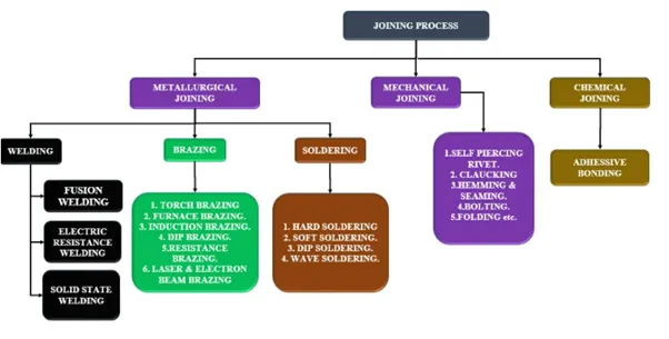
Figure Classifications of joining process
TYPES OF JOINING PROCESS
- The durability & performance of any structure largely depends on the quality & the design of the component joints. the whole structure cannot be mead in one piece.
Two fundamentals’ options for joining materials & components are,
- Metallurgical joining
- Mechanical joining
- Chemical joining
A.METALLURGICAL JOINING
Metallurgical joining is classified into
- Welding
- Brazing
- Soldering
Welding: The process of joining similar metals by the applications of heat is called welding. welding can be obtained with or without applications of pressure and with or without the addition of filler metals. which is known as an electrode. During welding, the edges of these metal pieces are either melted or brought to plastic condition. The welding process is used for making the permanent joint. Which is obtained by a homogeneous mixture of two materials.
Classifications Of Welding process: The types of welding process classified into
- Fusion welding
- Electric resistance welding
- Solid-state welding
- Fusion Welding
In infusion welding, the metal at the joint is heated to a molten state and then it is allowed to solidify
Pressure is not applied during the welding process and hence it is also called ‘non-pressure welding’.
The filler material may be required during this type of welding
Classification of fusion welding is
- Thermit welding
- Arc welding
- Gas welding
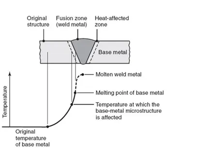
Figure- Fusion Weld Joint
- Thermit Welding
- Welding the part by using liquid thermit steel around the portions to be welded is called thermit welding .since it is a fusion welding process neither arc is produced to heat parts nor flame are used .for getting high temperature the exothermic reaction is used
- Welding principle is the heat of the thermit reaction used for welding in plastic state & mechanical pressure is applied for the joint
- It is depended on the chemical reaction between iron oxide & aluminum.
- The reaction in thermit welding is 8Al+Fe3o4=9fe+4al2o3. These reactions take place about 30sec only and the heat liberation temperature is about 2800 degrees Celcius is twice the melting temperature of steel
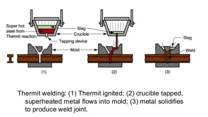
Figure-Thermit welding process
2. Arc Welding:
- In the arc welding process, the heat is developed by an electric arc. The arc is produced between an electrode and the work. This is a process of joining two metal pieces by melting their edges with an electric arc. In arcwelding the electrical energy is converted into heat energy.
- The electrode & the workpiece are brought nearer with similar a small air gap of 3mm approximately. Then the current is passed through the workpiece and the electrode to produce an electric arc. The workpiece is melted by an arc. The electrode is also melted and hence both the workpieces become a single piece without applying any external pressure. The temperature of the arc is about 5000°C to 6000 C The electrode supplies additional filler metal into the joints and is deposited along the joint A transformer or generator is used to supply a current. The depth to which the metal is melted and deposited is called depth of fusion To obtain a better depth of fusion, the electrode is kept at 70 inclination to the vertical
- The electrode used in arc welding is generally coated with a flox The flux is used to prevent the reaction of the molten metal with atmospheric air Also it removes the impurities of the molten metal and forms a slag. This slag gets deposited over the weld metal. This stag protects the weld seam from rapid cooling. The molten metal is forced out of the pool by an electric arc Hence a small depression is formed in the parent metal where the molten metal is oiled up. This is known as "arc carter The distance between the tip of the electrode and the bottom of the arc crater is called "arc length
. The types of arc welding are.
- Manual Metal Arc welding,
- MIG Welding.
- TIG Welding
- Submerged Arc Welding
- Plasma Arc welding,
- Atomic hydrogen arc welding.
- Carbon Arc welding
- Electroslag Welding
- manual Metal Arc Welding:
- Manual metal arc welding (MMA or MMAW) is also known as shielded metal arc welding(SMAW) or informally known as stick welding. • Stick welding is a process where the arc is struck between the metal rod (electrode flux coated) & workpiece, both the rod & the workpiece surface melt to create a weld.
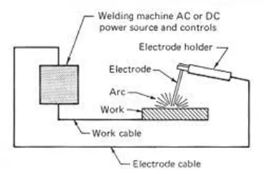
Figure- Arc welding
ii. MIG Welding
- MIG welding -metal insert Gas welding
- It is an arc welding technique in which a consumable electrode is used to weld two or more workpieces
- MIG welding makes use of the following components. Consumable electrode inert gas supply, welding head, AC or DC supply
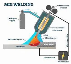
Figure- MIG welding
- Brazing
- Brazing is a metal-joining process in which two or more metal items are joined together by melting and flowing a filler metal into the joint, the filler metal having a lower melting point than the adjoining metal.
- Brazing differs from welding in that it does not involve melting the work pieces and from soldering in using higher temperatures for a similar process, while also requiring much more closely fitted parts than when soldering. The filler metal flows into the gap between close-fitting parts by the capillary. The filler metal is brought slightly above its melting temperature while protected by a suitable atmosphere, usually a flux It then flows over the base metal (known as wetting) and is then cooled to join the workpieces together. A major advantage of brazing is the ability to join the same or different metals with considerable strength.
There are different methods/techniques in brazing They are:
- Torch brazing
- Furnace brazing
- Silver brazing
- Braze welding
- Cast iron welding
- Vacuum brazing
- Dip brazing
I. Torch Brazing;
In this method, acetylene, natural gas & butane, or propane are combined with air, or oxygen is used to supply the required heat to melt the filler rod and diffuse the base metal. It is not used for mass production and flues are used in the form of paste or powder.
Furnace Brazing: In this process, the heat is supplied by gas or electric heating coils. The furnace can be either box type or continuous type. The preformed shape of filler metal is placed on the parts to be joined before entering the furnace. The use of flux can be avoided if an inert atmosphere is maintained in the furnace. It is used for mass production and the flux is used in the form of a paste
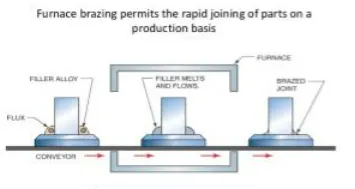
Figure- Furnace Brazing
II. Induction Brazing:
In this process also the filler metal is used in the form of a preformed shape. The parts are heated by placing within the field of a high-frequency induction coil The electric and magnetic resistances of the changing induction field are used to produce the eddy current. This eddy current is used to heat the metal. It is also used for mass production and the flux is used in the form of paste.
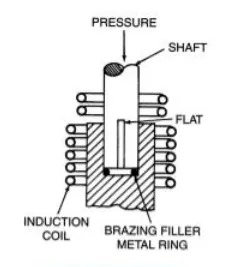
III. DIP Brazing:
Dip brazing is of two types. They are i) Chemical dip brazing: In chemical dip brazing, the parts with preformed filler metal are placed into a molten bath of flux. This method is mainly used for joining large parts. ii) Molten metal bath process: In this process, the assembled parts are first pre-fluxed & then immersed into a molten bath or filler metal. It is used only for joining smaller parts.
Advantages of Brazing
Following are the advantages of brazing:
- Dissimilar metals and parts having a thin section can be easy.
- brazing may avoid metallurgical damage to the base metal.
- The strong joint can be obtained by brazing.
- Properly brazed joints are pressure-tight.
- It is an economical and quick process.
- Less heating is required than for welding.
Disadvantages of Brazing
Following are the disadvantages of brazing:
- Reduction of joint strength compared to a welded joint due to the soft filler metals used.
- The strength of the brazed joint is less than that of base metal but is more likely to be higher than filler metal.
- The brazed joints can be destroyed under high service temperatures.
- Brazed joints need high-metal cleaning when done in an industrial setting.
- The joint color is usually different from the base metal, creating an aesthetic disadvantage.
Applications of Brazing
Following are the applications of brazing:
- It is used in vacuum interrupters.
- It is used in transport applications.
- Used in constructions.
- It is helpful in medical equipment.
- Used in art and jewelry.
3. SOLDERING
- The soldier is melted by using heat from an iron connected to a temperature controller. It is heated up to temperatures beyond its melting point at around 600 degrees Fahrenheit which then causes it to melt, which then cools creating the soldered joint.
- As well as creating strong electrical joints solder can also be removed using a desoldering tool.
- Solder is a metal alloy used to create strong permanent bonds; such as copper joining in circuit boards and copper pipe joints. It can also be supplied in two different types and diameters, lead and lead-free, and also can be between .032” and .062”. Inside the solder, the core is the flux, a material used to strengthen and improve its mechanical properties.
Metals are Used in Soldering
- Filler metals used in soldering were once lead-based (lead solder), however, owing to regulations, lead-based solders are increasingly replaced with lead-free solders, which may consist of antimony, bismuth, brass, copper, indium, tin, or silver.
- Types of Soldering
- There are three types of soldering which use increasingly higher temperatures, which in turn produce progressively stronger joints:
Soft soldering (90 °C - 450 °C) -
- This process has the lowest filler metal melting point of all the soldering types at less than 400°C these filler metals are usually alloys, often containing lead with liquidus temperatures under 350°C. Because of the low temperatures used in soft soldering, it thermally stresses components the least but does not make strong joints and is then therefore unsuitable for mechanical load-bearing applications. It is also not suited for high-temperature use as this type of solder loses strength and melts.
Hard (silver) soldering (>450 °C) –
- Brass or silver is the bonding metal used in this process and requires a blowtorch to achieve the temperatures at which the solder metals.
Brazing (>450 °C) –
- This type of soldering uses metal with a much higher melting point than those used in hard and soft soldering. However, similarly to hard soldering, the metal being bonded is heated as opposed to being melted. Once both the materials are heated sufficiently, you can then place the soldering metal between them which melts and acts as a bonding agent.
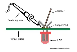
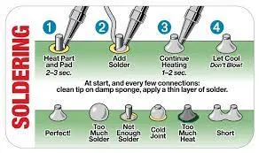
Figure- soldering
2. MECHANICAL JOINING
Mechanical joining includes bolting, riveting, caulking, shrink fitting, hemming, seaming, and folding all the methods are used to join the workpiece by using Mechanical Energy.
- self -Piercing Riveting:
- it is a high-speed mechanical fastening process for joining sheet material, typically steels & aluminum alloys, It is a single-step technique generally using a semi-tubular rivet to clinch the sheet in a Mechanical Joint.
- As the name suggests Pre-Drilling holes are not required, allowing the joint to be made rapidly in one operation.
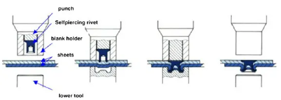
Figure- Self-Piercing
2. Hemming & seaming process
hemming & Seaming are two similar metalworking processes in which a sheet metal edge is rolled over on itself.
Heming is a process in which the edge is rolled flush to itself, while a seam joint the edge of two materials. Hems are commonly used to reinforce an edge, hide burrs and rough edges, and improve appearance. Seams are commonly used in the food industry on canned goods, amusement park cars, metal roofing (with a roof seamer), and in the automotive industry. The process for both hemming and seaming are the same, except that the tonnage requirement is greater for seaming. The process starts by bending the edge to an acute angle. A flattening die is then used to flatten her. The below figure illustrates hem formation.
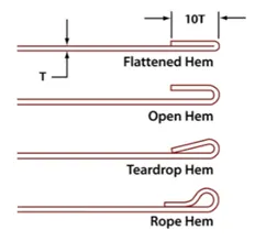
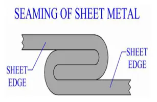
Figure- Heming Figure- Seaming
all. BOLTING
the bolted joint is one of the most common elements in construction and machine design they consist of fasteners that capture and join other parts and are secured with the matting of screw threads.
- There are two main types of bolted joint designs are Tension joint and shear joint
- In the tension joint, the bolt and clamped component of the joint is designed to transfer an applied tension load through the joint by way of the clamping components by the design of a proper balance of joint and bolt stiffness. The joint should be designed such that the clamp load is never overcome by external tension force acting to separate the joint. if the external tension force overcomes the clamping load. the clamped joint component will separate .allowing relative motion of the components.
- The second type of bolted joint transfers the applied load in shear of the bolt shank and relies on the shear strength of the bolt. Tension loads on such a joint are only incidental. A preload is still applied but consideration of joining flexibility is not critical as in the case where loads are transmitted through the joint in tension .others such shear joints do not employ a preload on the bolt as they are designed to allow rotations of the joint about the bolt but use other methods of maintaining bolt/joint integrity .joints that allow rotation includes clevis linkages, and rely on a locking mechanism (like lock washer, thread adhesives, and lock nuts)
C.CHEMICAL BONDING
Chemical joining includes Adhesive Bonding
Adhesive bonding
Adhesive bonding is used to fasten two surfaces together usually producing a smooth bonding
The joining technique involves glues, epoxies, or various plastic agents that bond by evaporation of solvent or by curing a bond agent with heat, pressure, or time
Adhesive bonding (also referred to as gluing or glue bonding) describes a wafer bonding technique with applying an intermediate layer to connect substrates of different types of materials. Those connections produced can be soluble. the commercially available adhesive .especially the well-established SU-8 and benzocyclobutene(BCB).are specialized for MEMS or Electronic Components produced
- Adhesive material
- Coating thickness
- Bonding temperature
- Process time
- Chamber pressure
- Tool pressure
- Adhesive bonding has the advantage of relatively low bonding temperature as well as the absence of electric voltage and current. Based on the fact that the wafers are not in direct contact, this procedure enables the use of different substrates, eg, silicon, glass, metals, and other semiconductor materials. A drawback is that small structures become wider during patterning which hampers the production of an accurate intermediate layer with tight dimension control.
- Further, the possibility of corrosion due to out-gassed products, thermal instability, and penetration of moisture limits the reliability of the bonding process.
- Another disadvantage is the missing possibility of hermetically sealed encapsulation due to the higher permeability of gas and water molecules while using organic adhesives.
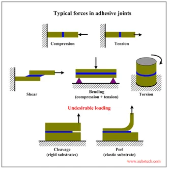
Figure-Typical forces in Adhesive bonding
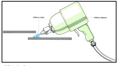
Figure- Glue Bonding
3. What is Resistance Welding & its application in the automotive sector?
ELECTRIC RESISTANCE WELDING
Resistance welding is a welding technique widely used in the manufacturing industry for joining metal sheets & components. This type of welding is very much used in BiW assemblies most commonly. The weld is made by conducting a strong current through the metal combination to heat up & finally melt the metals at localized points predetermined by the design of the electrodes or the workpiece to be welded. A force is always applied before, during, and after the application of the current to confine the contact area at the weld interfaces and in some applications to forge the work pieces. Resistance welding is used in mass production for welding sheet metals, wire & tubes. It is also used in welding bars, boxes, cans. rod pipes & frame metals of medium & high resistance such as steel, stainless steel, Monel metal & silicone bronze which are easy to weld.
Types of Resistance welding are,
- Resistance Spot welding
- Resistance Seam welding
- Resistance Projection welding
- Butt welding
- Precision welding
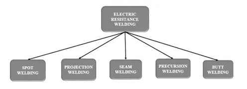
Figure- Classification of resistance Welding
l. Resistance spot Welding (RSW)
- The process is used for joining sheet materials & uses shaped copper-chromium or zinc conium alloy electrodes to apply pressure and convey the electrical current through the workpiece Heat is developed mainly at the interface between two sheets, eventually causing the material being welded to melt, forming a molten pool the weld nugget
- The molten pool is contained by the pressure applied by the electrode tip & the surrounding solid metal
Working Principle of Resistance Spot Welding
The resistance spot welding process uses two copper alloy electrodes to concentrate weld current and forced between work to be welded Produce coalescence in one spot for heat generated from resistance to the electrical current through workpiece held together under pressure by an electrode. It process usually the thickness range of sheet metal is 0.5 to 3,0 mm. the small spot is quickly heated until the melting point in this reason a nugget of welded metal after power supply is removed. When the current is applied too long, which results in molten metal become expelled as-welded splash (or) can be made a have right through the material become welded. This spot welding is used for welding steel sheets.
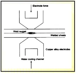
Figure- principle Resistant spot Welding
Advantages of Resistance spot welding:
- Short weld time and hence high weld speed.
- Highly adaptable to automation & Robotics.
- Typical BIW contains 5000 welds.
- The strength & durability of automobile largely depends on the quality of RSW.
Disadvantages of Resistance spot welding
- The electrodes have to be able to reach both sides of the pieces of metal that are being joined together. A particular spot welding machine will be able to hold only a certain thickness of metal-usually 5 to 50 inches--and although the position of the electrodes can be adjusted, there will be only a limited amount I movement in most electrode holders.
- The size and shapes of the electrodes will determine the size and strength of the weld. The join forms only at the spot where the electrodes are in contact with the metal. If the current is not strong enough, hot enough, or the metal is not held together with enough force, the spot weld may be small or weak
- Warping and a loss of fatigue strength can occur around the point where metal has been spot welded. The appearance of the join is often rather ugly, and there can be cracks. The metal may also become less resistant to corrosion.
Applications of Resistance spot welding,
- The most common application of spot welding is in the automobile manufacturing industry, where it is used almost universally to weld the sheet metal to form a car
- Spot welding is also used in the orthodontist's clinic, where small-scale spot welding equipment is used when resizing metal "molar bands used in orthodontics
- Another application is spot welding straps to nickel-cadmium, nickel-metal hydride, or Lithium-ion battery cells to make batteries. The cells are joined by spot welding thin nickel straps to the battery terminals. Spot welding can keep the battery from getting too hot, as might happen if conventional soldering were done.
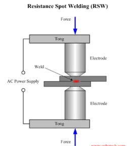
Figure- Resistance Spot Welding
ll. Resistance Seam Welding
Seam welding is a resistance welding process for joining metal sheets in continuous often leak-tight seam joints by directly applying opposing forces with electrodes consisting of rotary wheels
- The current & the heat generation are localized by the peripheral shapes of electrode wheels
Working Principle of Resistance Seam Welding:
- Two electrodes made from copper & in a circular form are used. An impulse current is applied through one of the discs & pressure through the other on the materials that are being joined. When the material passes between electrodes they rotate. In this way, the electrode remains in contact with the material for a long time & forms a weld joint progressively unlike spot welding which forms an entire joint at once.
- Seam welding core principles are similar to that of the Resistance spot welding, Time, pressure & electricity are used to weld metals together. It is a type of electric resistance welding,
If the current is quickly turned OFF & ON a continuous fusion zone of overlapping nuggets is formed then this process is called STICH
WELDING PROCESS
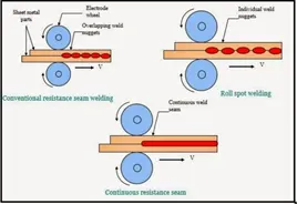
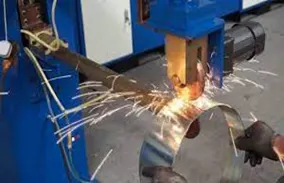
Figure- Resistance Seam Welding Process
Advantages of Resistance Seam Welding
1 This welding is a quicker process than spot welding
- It is a continuous welding technique suitable for gas & liquid tight containers.
- Energy is utilized efficiently in this technique
- This technique is ideal for making gas or liquid-tight vessels
- It doesn't need the use of filler material.
- No pollutions like fumes of gases because filler material is not utilized.
- This technique can produce liquid-tight & gas-tight joints
- Since the joint is forged due to heat & pressure, a durable weld is formed in seam welding
- The welding is easy to operate.
10 Seam welding gives sturdy design & excellent performance.
Disadvantages of Resistance Seam Welding:
- Higher current is required as compared to spot welding.
- For harder alloys, high-strength welding forces are required.
- The electrode may need to be cleaned after one revolution.
- A mechanized cleaning system is necessary for the removal of contaminations.
- This technique is not utilized when the thickness of the sheets increases from 3MM.
- If electrodes & ravel speed are not controlled efficiently then its performance may be decreased.
- Workpieces need to be overlapped to make sure that no overflow of melted metal occurs.
- It requires a greater amount of current.
- Its electrodes are motor-driven as compared to stationary electrodes.
Application of Resistance Seam Welding: Seam welding applications include,
- It is used in the assembly of fuel tanks in the automotive industry.
- Especially used in the case of seam-welded tubing & pipes.
- It is used when the fabrication of gas or liquid-tight metal sheets is needed.
- It is also used in the fabrication of heat exchangers.
- Earlier seam welding was used to produce steel beverages cans but not currently used.
- This welding is used to make leak-proof tanks. drums, radiators, household utensils, automobile bodies, etc
well. RESISTANCE PROJECTION WELDING
In projection welding, as per the name, different projections are formed for effective welding Projection Welding is one of the types of resistance welding and its working principle is quite the same as resistance welding. The only difference here is that projection or embossed joints are used for welding purposes.
- Projection welding is a resistance welding process for joining metal components or sheets with embossments by directly applying opposing forces with electrodes specially designed to fit the shapes of the workpieces. The current & the heat generation are localized by the shape of the workpiece either with their natural shapes or with specially designed projection. Large deformation or collapse will occur in the projection part of the workpieces implying high
Working Principle of Resistance Projection welding:
As per the definition, different projections are formed in this welding technique. Here, the metal pieces that are to be joined are kept in between the two electrodes. A larger pressure force is applied to the electrodes. As current is passed through the system, the heat formation takes place due to the internal resistance of the metal workpieces. One point that you must note down here, is that the heat generation takes place due to the internal resistance of the metal workpieces rather than an electric arc. Those projections concentrate the heat. As the pressure applied to the electrodes increases, this projection collapses and the formation of the fused weld nugget takes place. Thus, a quality weld is formed
The exact working of the projection welding can be understood by referring to the below image.
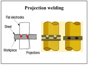
Figure- Resistance Projection Welding
You can see in the above image that the projection means the embossed joints are formed on one of the base metals and then, these base metals are kept in between the two electrodes, and force is applied perpendicular to the electrodes.
But as the applied force increases those sharp projections collapse and the formation of the weld takes place at the weld surface. The above image illustrates the formation of the weld nuggets as well as the collapsing of the sharp projections.
Advantages of Resistance Projection Welding:
- As the above stated, this welding requires a very small supply of current, and thus, it saves electricity usage. So, less electricity requirement and a longer electrode life are the two most prominent benefits of this welding process.
- While doing spot welding there is a limitation on the thickness of the metal that has to be welded. But in this welding, almost all metals of all thicknesses are welded.
- It can be used effectively for welding the joints which are in complicated locations.
- The heat balance is an important part of any welding process and this welding gives a good heat balance while welding.
Disadvantages of Resistance Projection Welding:
- This welding process is not applicable for some types of coppers and brasses. Projection formation is a quite complicated process and it takes time to form the projections. It is very difficult to form the spherical projection and a skilled person is required to form such projections. While making those projections, the height of the projection has to be maintained properly.
- This process does not apply to all types of workpieces. The composition of the metal workpieces has to be considered while this process and it has some limitations.
Application of Resistance Projection Welding
Projection welding is mostly used for mass production. It has many applications such as:
- The automobile industry uses projection welding to a very large extent.
- Used for mechanical fixing of automobile body structures like weld nuts etc.
- This welding process is also used for the fan covers and hollow metal doors.
. It is also used for producing the compressor parts and for the semi-conductors.
- Have you heard about diamond segment welding? In diamond segment welding, projection welding finds its applications.
4. What is fusion welding & types of fusion welding with their application in the automotive sector?
FUSION WELDING:
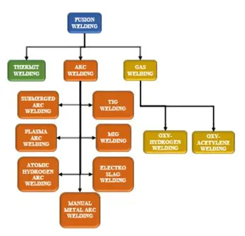
In infusion welding, the metal at the joint is heated to a molten state, and then it is allowed to solidify. Pressure is not applied during the welding process and hence it is also called 'non-pressure welding Filler materials may be required during this type of welding Classification of fusion welding is.
- Thermit welding.
- Arc Welding,
- Gas Welding
A.Thermit Welding:
Welding the parts by using liquid thermit steel around the portions to be welded is called thermit welding Since it is a fusion welding process neither arc is produced to heat parts nor flames are used. For getting a high temperature, the exothermic reaction is used.
- Welding principle is the heat of the thermit reaction used for welding in plastic state & mechanical pressure is applied for the joint.
Advantages of Thermite welding
- It is a simple and easy process.
- Low setup cost.
- The metal joining rate is high.
- Thermite welding can be done at sites where casting is impossible.
- This can be used where a power supply is not available.
Disadvantages of Thermite welding:
- It is used for limited metals like iron and copper
- . It is uneconomical for welding light parts.
- Highly depends on environmental condition like moisture content, workpiece alignment, etc.
Application of Thermite Welding:
It is moused to weld railroad at the site.
- It was used to weld thick plates before introducing electro slag welding
- They are used to repair heavy castings
- It is used to weld cable connectors of copper,
. It is used to make structure joints in large ships etc.
- It is used to joint pipe, thick plate, etc, where a power supply is not available. • Automobile parts are welded by this process.
B.Arc Welding
- The process involves either a consumable or a non-consumable electrode (Rod or Wire). • An arc produced between the tip of the electrode & workpiece to be welded by use of an AC or DC supply.
- Types of arc welding are,
- Manual Metal Arc welding
- MIG Welding.
- TIG Welding.
- Submerged Arc Welding.
- Plasma Arc welding,
- Atomic hydrogen arc welding
- Carbon Arc welding
- Electroslag Welding
- Manual Metal Arc Welding
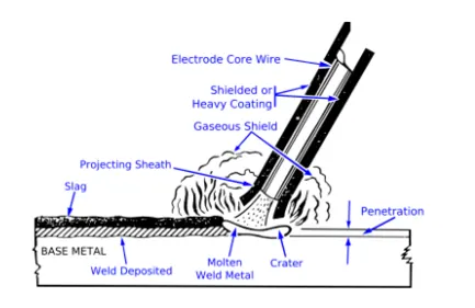
- Manual metal arc welding (MMA or MMAW) also known as shielded metal arc welding (SMAW) or informally known as stick welding
- Stick welding is a process where the arc is struck between the metal rod (electrode flux coated) & workpiece, both the rod & the workpiece surface melt to create a weld
Working Operation of Manual metal Arc welding: To strike the electric arc, the electrode is brought into contact with the workpiece by a very light touch of the electrode to the base metal The electrode is then pulled back slightly. This initiates the arc and thus the melting of the workpiece and the consumable electrode, and causes droplets of the electrode to be passed from the electrode to the weld pool Striking an arc.
which varies widely based upon electrode and workpiece composition can be the hardest skill for beginners. The orientation of the electrode to the workpiece is where most stumble if the electrode is held at a perpendicular angle to the workpiece the tip will likely stick to the metal which will fuse the electrode to the workpiece which will cause it to heat up very rapidly. The tip of the electrode needs to be at a lower angle to the workpiece, which allows the weld pool to flow out of the arc. As the electrode melts, the flux covering disintegrates, giving off shielding gases that protect the weld area from oxygen and other atmospheric gases. In addition, the flux provides molten slag which covers the filler metal as it travels from the electrode to the weld pool: Once part of the weld pool, the slag floats to the surface and protects the weld from contamination as it solidifies Once hardened, it must be chipped away to reveal the finished weld. As welding progresses and the electrode melts, the welder must periodically stop welding to remove the remaining electrode stub and insert a new electrode into the electrode holder. This activity.
combined with chipping away the slag, reduces the amount of time that the welder can spend laying the weld, making SMAW one of the least efficient welding processes in general, the operator factor, or the percentage of operator's time spent laying weld, is approximately 25%
Advantages of Manual Metal Arc welding
- Lower equipment cost than GTAW, FCAW,, and GMAW. (No bottle, gas hose, flowmeter, and tig rig/Wire feeder needed
2 Quick Change from one material to another
- The process lends itself to welding in confined spaces and various positions with few problems.
4 Deposition Rates faster than GTAW Manual
- Easy to move from one location to another. No Wire Feeder and Bottle
6 Some special electrodes are made for cutting/gouging
- Requires no outside t elding gas and can be used outdoors in light to medium wind.
- The ability to bend the electrode and the small space the electrode takes allow the process to be used in comparatively tight spaces.However,, keep in mind that for some jobs one of the other processes may also work or even work better. The FCAW-Self Shielded process can weld with a very long electrode stick out
Disadvantages of Manual Metal Arc welding:
- Low deposition rate compared to GMAW/FCAW.
- Filler metal cost per weld can be greater due to a low deposition efficiency that can vary greatly with stub length.
- Production factor is typically lower (Unless welding on various materials) due to rod changes and chipping slag.
- Needs more hand-eye coordination than GMAW/FCAW.
- Slag must be removed as compared to GTAW/GMAW
Application of Manual Metal Arc welding
Applications of the SMAW process are varied and widespread. Depending upon the matel electrodes available it finds extensive use in all major fabrication industries which may include items of sundry repairs to shipbuilding and pressure vessel fabrication.
- Electrodes for welding low carbon steels
1 Cellulose Coated Electrodes are used in Pipelines, tanks, pressure vessels, structural, and fieldwork where deep penetration is necessary. Especially suited for pressure pipelines that cannot be welded from inside.
- Rutile Coated Electrodes are used in Storage tanks, gear blanks, machinery, steel furniture, truck bodies, foundry equipment, shaft build-up,, etc.
- used in Structures, building construction, tanks pipelines, machinery parts automobile bodies, steel window frames, farm machinery, etc.
- Used in Building construction, vessels, tanks and boilers, pipelines bridges, railway wagons, ships, trailers.Pressure pipelines that cannot be welded from inside, oil storage tanks, railway coach panels Locomotive fire-boxes, scooter frames
- Rutile Plus Iron Powder Coated Electrodes Used for welding pressure pipelines, oil storage tanks, ships, boilers, railway wagons, etc. at high welding speeds. Also well suited for repairing steel castings
- Used for welding of heavy structures like crane and bridge girders, assembly of earthmoving equipment, heavy machinery parts, etc.
- Useful for high-speed welding of heavy structural like crane and bridge girders, assembly of earthmoving equipment, and parts of heavy machinery, etc.
- Acid Coatings Used for welding heavy structural work, bridges, cranes, locomotive fireboxes, truck chassis, and frames, Excellent for continuous down-hand, horizontal fillet welds, and vertical-up welding
- Basic coating Used for welding blast furnace steelwork, atomic reactor shell and pipework, heavy welded fabrications as replacements for castings, bridges, penstocks, root run in heavy and restrained joints. Also used for welding steels designed for service at sub-zero temperatures down to-33 C
- Special coating Used for welding of heavy deck plates, structural, etc. by the deep penetration technique thus it avoids beveling and refilling of groove. It can also be used for depositing sealing run on the backside without the necessity of chipping out the root, and for depositing fillet welds with penetration beyond the root as in plate girders for bridgework
- Electrodes for Welding Low Alloy and High Tensile Steels:
- Cellulose Coatings Used for welding C-Mo piping, road building equipment, boilers, pressure vessels, alloy steel chain links, truck frames and bodies, high tensile steel pipelines for oil and gas transmission. Also recommended for welded fabrication to be used for service at elevated temperature up to 525°C.
- Rutile Coatings Recommended for welding medium-high tensile and low alloy steel of 0-5% Mo, and 1% Cr-0-5% Mo compositions. Also recommended for welding steels used in boilers, power plants, oil refineries,, and chemical plants in the form of structural and pipes for elevated temperature service up to 525 °C.
- Used for welding pipes and structures in boilers, power plants, oil refineries, and chemical plants for elevated temperature service up to 550°C.
- Used for welding pipes and structural in boilers, oil refineries, and chemical plants for service at elevated temperatures up to 600°C.
- Basic Coated Electrodes Used for welding high carbon steel parts, high carbon steel to mild steel, low alloy steels, steels relatively high in sulfur, cast steels, and steels of unknown composition.
- Suitable for welding bridges, heavy machinery, penstocks, heavy parts of earthmoving equipment,, and in general for carbon steel and low alloy steel fabrications where severe service conditions are to be met. Also recommended for welding steels designed for use at sub-zero temperature down to-40°C.
Coated Electrodes for Welding Stainless Steels and Heat-resisting Steels:
- 1 Used for welding of 18Cr-8Ni stainless steels represented by AISI grades 301, 302, 304,, and 308 having very low carbon contents. Welding of utensils, spoon,, and forks, household articles, hospital apparatus, apparatus for handling nitric acid, acetic acid,, and citric acid. Also used for welding components required in the soap industry, dairy industries, chemical,, and fibre industries as well as for fabricating aircraft frame.
- Used for welding 18/8 Cr-Ni, Mo-Nb or Titanium stabilized steels such as AISI 318 grade paper mill equipment, bleaching equipment. chemical plants, dyeing equipment, pickling plant, heat-resisting castings, etc. Can also be used for welding non-stabilised steels of the types AISI 316 and 317 grades.
- Used for welding AISI steel 321 and 347 grades. Generally used for welding 18/8 Cr-Ni sheets of steel stabilised with titanium or niobium. Also recommended in the manufacture of equipment for the chemical, food processing,, and aircraft industries, for welding of gas turbines, and equipment for soap industry. Can also be used for welding un-stabilised stainless steel, for example, AISI 301,302, 304,, and 308 grades.
- Used for welding paper mill equipment, bleaching equipment, chemical plants handling sulphuric, sulfurous, hydrochloric, acetic, formic, citric, tartaric acids, etc. Dyeing equipment, pickling plant, heat-resisting casting, and bakery equipment Also used for welding AISI 316 and 318 grades stainless steels when maximum corrosion resistance is required.S. Used for welding 25/20 Cr-Ni stainless and other grades of heat-resisting steels. For butt-welding spring steels, high-temperature furnace parts, preheater tubes for high-pressure boilers, and annealing boxes. Also used for welding high carbon steels, air-hardening steels, high-Mn steels, cast armor steels, and rolled armor steels.
- 6 Used for welding heavy sections of steel armatures and the repair of cast parts such as in turbine construction and welding similar corrosion-resistant chrome steels and steel castings: for welding low-priced stainless steel cutlery, pump parts, oil refinery equipment. coal washers, etc. Also used for welding s required for general corrosion and heat-resisting applications
- It is specially designed for welding austenitic Mn-steel (12% Mn) to mild steel for producing crack-free joints in difficult to weld steels and high alloy steels including armor plate, repairing cracks in austenitic Mn-steel castings, surfacing parts subject to wear and tear, for example, rail points and crossings, laying buffer layer on difficult to weld steels before hard facing, etc.
II. MIG Welding:
- MIG Welding - Metal Inert Gas Welding.
- It is an arc welding technique in which a consumable electrode is used to weld two or more workpiece.
- MIG welding makes use of the following components: Consumable electrode, Inert gas supply, welding head, AC or DC Supply.
Working Principle of MIG welding:
Its work can be summarized as follow.
- First, a high voltage current is changed into DC supply with a high current at low voltage. This current passes through the welding electrode.
- A consumable wire is used as an electrode. The electrode is connected to the negative terminal and workpiece from the positive terminal.
- A fine intense arc will generate between electrode and workpiece due to power supply. This arc is used to produce heat which melts the electrode and the base metal. Mostly electrode is made by the base metal for making the uniform joint.
- This arc is well shielded by shielding gases. These gases protect the weld from other reactive gases which can damage the strength of the welding joint.
- This electrode travels continuously on the welding area for making proper weld joint. The angle of the direction of travel should be kept between 10-15 degrees. For fillet joints,, the angle should be 45 degrees.
Application of MIG Welding:
- MIG is best suited for the fabrication of sheet metal.
- Generally,, all available metals can be weld through this process.
- It can be used for deep groove welding.
Advantages of MIG welding:
- It provides a higher deposition rate.
- It is faster comparing to arc welding because it supplies filler material continuously.
- It produces a clean weld with better quality.
- There is no slag formation.
- Minimize weld defects.
- This welding produces very little slag.
- It can be used to make deep groove welds.
8. It can be easily automated.
Disadvantages of MIG welding:
- It cannot be used for welding in difficult-to-reach portions.
- Higher initial or setup cost.
- It cannot be used for outdoor work because wind can cause damage to the gas shield.
- It required high skilled labor.
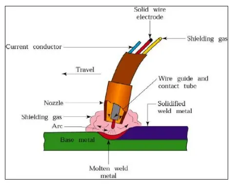
Figure-MIG Welding
III. TIG Welding
.TIG Welding - Tungsten Inert Gas welding.
It is an arc welding method that uses a non-consumable tungsten electrode to weld two or more workpieces
- It is very much similar to MIG Welding
- The following components are required to perform TIG welding They are Power supply,Non-consumable tungsten electrodes, Inert gas supply Filler rod(depends on nature of workpiece), welding head.
Principle of TIG Welding:
TIG welding works on the same principle of arc welding In a TIG welding process, a high intensity arc is produced between a tungsten electrode and workpiece. In this welding mostly the workpiece is connected to the positive terminal and the electrode is connected to the negative terminal. This arc produces heat energy which is further used to join metal plates by fusion welding. Shielding gas is also used which protect the weld surface from oxidization
Working process of TIG welding
The working of TIG welding can be summarized as follow.
- First, a low voltage high current supply is supplied by the power source to the welding electrode or tungsten electrode. Mostly, the electrode is connected to the negative terminal of the power source and the workpiece to the positive terminal.
- This current is supplied form a spark between the tungsten electrode and workpiece. Tungsten is a non-consumable electrode, which gives a highly intense arc. This arc produced heat which melts the base metals to form a welding joint.
- The shielded gases like argon, helium are supplied through a pressure valve and regulating valve to the welding torch. These gases form a shield that does not allow any oxygen and other reactive gases into the weld zone. These gases also create a plasma which increases the heat capacity of the electric arc thus increases welding ability.
. For welding thin material no filler metal is required but for making a thick joint some filler material is used in form of rods which are fed manually by the welder into the welding zone.
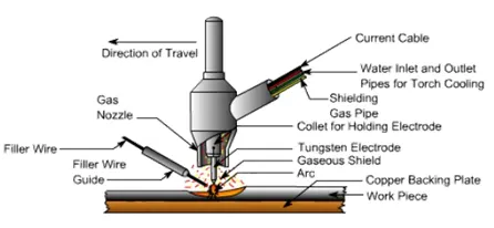
Figure-TIG Welding
Application of TIG Welding:
- Mostly used to weld aluminum and aluminum alloys.
- It is used to weld stainless steel, carbon base alloy, copper base alloy, nickel base alloy, etc.
- It is used to welding dissimilar metals.
- It is mostly used in aerospace industries.
Advantages of TIG Welding:
- TIG provides a stronger joint compare to shield arc welding.
- The joint is more corrosion-resistant and ductile.
- A wide verity of joint designs can form.
- It doesn't require flux.
- It can be easily automated.
- This welding is well suited for thin sheets.
- It provides a good surface finish because negligible metal splatter or weld sparks that damage the surface.
- The flawless joint can be created due to non-consumable electrodes.
- More control on welding parameters compare to another welding.
- Both AC and DC can be used as a power supply.
Disadvantages of TIG Welding:
- Metal thickness to be weld is limited to about 5 mm. It required high-skill labor.
- Initial or setup cost is high compare to arc welding
- It is a slow welding process
IV Plasma arc welding:
The Plasma arc welding (PAW) is similar to GTAW or gas tungsten welding. In this kind of welding process, the arc will generate among work part as well as the tungsten electrode. The major dissimilarity among plasma arc welding and gas tungsten welding is that the electrode is located within the torch of Plasma arc welding. It can be heated the gas at the temperature of 30000'F & changes it into the plasma to attack the welding region. Below figure show working principle of plasma arc welding.
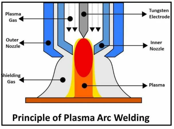
Figure-Plasme Arc Welding
Advantages of Plasma Arc Welding:
- Penetration is uniformed.
- Arc stability is good.
- High accuracy weld can be produced.
- High speed weld can be obtained.
Disadvantages of Plasma Arc Welding:
- Huge noise occurs during welding.
- Chnace of electric hazards during welding.
- It is limited to high thickness application.
- UV radiations can affect humans.
- Gas consumption is high.
Applications of Plasma Arc Welding:
- Used in aerspace application.
- used for melting titanium plates.
- used for welding nickel alloys.
- used for tube millapplications
V. Submerged Arc Welding:
The Submerged arc welding (SAW) can be extensively utilized within an automatic welding method. In this kind of welding process, an electrode is completely submerged by the granular coating of flux, and this flux can be an electric conductor which will not oppose the electric supply. The solid coating of flux stops the melted metal to ultra-violate radiation and atmosphere. Below fig, show
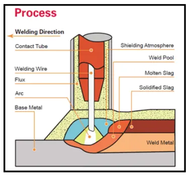
Automotive application of arc welding technology:
- Arc welding is used to weld the chassis parts in automotive industry.
- Arc welding is used to weld body parts in automotive industry. Low heat input welding of thin steel sheets prevention of burn through due to excessive heat input is important in the welding of car body parts of thin sheets. For this reason thin welding wire with a diameter of 0.9 mm, which enable welding at low currents & low heat input welding power source.
- TIG welding is used to join thin stainless steel parts & various piping parts in automobile industry. TIG welding can work on both AC and DC power sources. One of the greatest strengths of TIG welding is that it can be used for welding non-ferrous metals like aluminum, copper, magnesium, copper, nickel, titanium, etc.Rebuilding MIG welding is used for repairing work in automobile industry. To repair especially to dismantle & reassemble with new parts.Example to rebuild an old car. When it comes to fixing broken parts in the field, there are three steps to master cutting & removal of the failed component, preparation of the new joint/ part, welding & cleanup. Worn parts can be repaired using MIG welding in variety of coatings (stainless steel, bronze, nickel, aluminum or hard surfacing) & in a range of hardness, for a fraction of the cost of purchasing a new part.
VI.Gas Welding:
- Gas welding is one type of welding process in which the edges of the metals to be welded are melted by using gasflame. No pressur is applied during welding except pressure gas welding.
- The flame is produced at the tip of the welding torch.
- The gases commonly employed for gas welding are acetylene, hydrogen, propane & butane.
- Metal 2mm to 50mm thick are welded by gas welding.
There are three types of welding process used in industries such as,
- Oxy-acetylene welding.
- Oxy - hydrogen welding.
- Air-acetylene welding
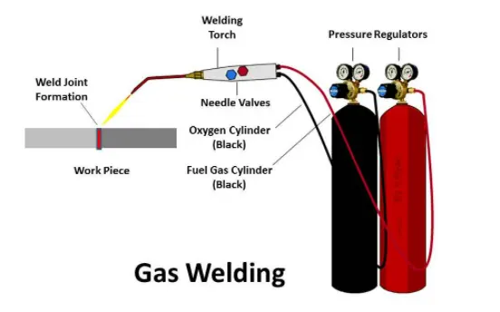
- Air-acetylene welding.
In this welding the heat obed by baminga mature of ongen & combushble gas. The gases are moved in the required proportion in a welding tech which provides control for the welding fame. The most common form of gas welding as Oxy-acetylene welding
The fame andy willme the men Saisonal metal to the weld is supplied by the filer rod A flux is used during weldingto prevent The temperature of oxy-acrylene fame in its homest regions about 3200C
The cost of acrylene alow The gases O2C28H2 can be stored at high pressure in separate steel cylinders But the acetylene is very There are two types al sy-acetylene systems employed depending upon the manner in which acetylene is supplied for welding They are High pressure system & Low pressure system.
In High pressure system, both cygen & acetylerse are supplied from high pressure cylinders
- In Low pressure system, the acetylene produced at the place of welding by interaction of calcium carbide & water in acetylene generator.
2.Chry-hydrogen welding
This process is similar to Oxy-acetylene welding process. Hence the oxygen & hydrogen gases are mixed with the required proportion for In this process. Special regulator is used to metering the hydrogen gases
. It was once used extensively to weld the low temperature metals such as aluminium, lead, magnesium but it is not use in today because more versatile & faster welding process has been developed.
3. Air Acetylene Welding
. This process also similar to that of oxy-acetylene welding process. Here air is used instead of oxygen.
- The air taken from the atmosphere is compressed in a compressor & mixed with acetylene to the required poportion in the torch
- This type of weiding is in limited use as temperature is lower than that obtained by other gas process.
- Itis sucessfully used in lead welding & many low melting terriperature metals & alloy.
Advantages of Gas welding
- temperature of flame can be easily controlled.
- The flame can be used for welding & cutting
- All types of metals can be welded
- Cost of equipment is less
- Maintainance cost is less
Disadvantages of Gas welding
Lit is not suitable for joining thick plates
- Strength of weld a not so good as arc welding
- Handing & storing of gas cylinders needs more care
Applications of Gas welding
- Repair works: One of the most common applications of gas welding is for repair works
- Fabrication of sheet metal Thin to medium sheet metals are easily weld using gas welding
- Arcrait industry: Ory-Acetylene wedding as used in joining various aircraft parts
- Automotive industry Used to weld parts of the frame and the chassis
- Joining High carbon Steel Gas welding is very effective in melting high carbon steel
FUSION WELDING APPLICATIONS IN AUTOMOTIVE SECTORS
- Fusion welding is used in the manufacturing of automobiles and construction equipment
- Gas welding-Used to weld parts of the frame and the chassis
- Manual metal arc welding truck frames and bodies Heavy machineries, two-wheelers frames, earth moving equipments etc.
- used to join vanous autobole parts
Hence, The Fusion welding & its types are discussed in deatail with their working principles, advantages, disadvantages & Applications. Also
the application of Fusion welding in automotive sectors are explained in detail
5. What is the 3-2-1 principle?
Degrees of freedom: The degree of freedom defines as the capability of a body to move. Consider a rectangular box, in space the box is capable of moving in twelve different directions (six rotational & six axial).
6 translational degrees of freedom: -X, -X, Y.-Y. Z.-Z.
And 6 rotational degrees of freedom:
Clockwise around the X-axis (CROT-X).
-Anticlockwise around the X-axis (ACROT-X).
Clockwise around the Y-axis (CROT-Y).
- Anticlockwise around the Y-axis (ACROT-Y).
- Clockwise around the Z-axis (CROT-Z)
- Anticlockwise around the Z-axis (ACROT-Z).
Each direction of movement is counted as one degree of freedom. i.e. a body in space has twelve degrees of freedom.
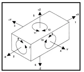
The above figure shows a body in space & its possible direction of movement. The body can move two directions along each as of three mutually perpendicular also can rotate about this axis either clockwise or antidote. There are twelve degrees of freedom for a body in the machining process to attain specific results, the degrees of freedom are constrained by using work holding devices, JG & feature & locating devices. There must be a definite relationship between the cutting tool & the surface of the workpiece to perform the accurate cutting operation. To achieve high precision in machining the workpiece must be located accurately it is called locating of workpiece Location of components is significant to the design of JG & fixture so that it influences the accuracy of the final product. The locating device is designed so that each successive workpiece loaded must occupy the same position in work handling devices
Locating the positional & dimensional relationship between workpiece & cutting tool.
Locator, the device to establish & maintain the position of the workpiece in work holders such as Jg & fixture to ensure repeatability of work
The best & most effective method of part location is the 3-2-1 principle Holding fixtures used in assembly operations often follow a 3-2-1 locating scheme to position parts Under this scheme, three locators position a part in a primary plane or direction leg, highlow). Two locators thems position the part in the second direction. not, leaving one locator for the tertiary direction (eg, fore/aft). This approach fixes the part in 3-dimensional space and satisfies the six degrees of freedom constraint
3) minimum plane. The locator blocks to establish the part plane. The locator or supports are placed under the workpiece Three locators are usually portioned on the primary locating surface. This restricts one coal movement downward & 4 radial movements Together, the three locations
(2) Round locating pin in a round hole that defines the location in four directions 14 ways perpendicular to the plane previously established. This
(1) Round locating pin in a dot that defines two of the other pin (2-way). restricts two axial movements
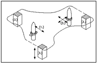
The better way of understanding of 3-2-1 principle considers 12 degrees as of 6 degrees of freedom. It includes clockwise & anticlockwise as one rotation. Movement in +ve & -ve direction as one translation motion. So we have three translation motions in x, y, z-axis & three rotational motions about x, y, z-axis
- In this, (3) means restricting three degrees of freedom as translation motion in z-axis i.e. upward & downward, two rotational motion about x & y-axis.
- Secondly, (2) means restricting two degrees of freedom. Translation motion in x (i.e. +ve or -ve) & y direction i.e. (-ve or-ve) & (1) means restricting one degrees of freedom i.e. rotational motion about z-axis clockwise or anticlockwise. So car panel or body cannot move
- in any direction with or without application of external force so properly fixed in the fixture. This is the basic concept of designing fixtures.
Conclusion:
The jig and fixture are tools used for holding the workpiece in a correct location for mass production. Various types of fixtures (like drilling fixtures, milling fixtures, and welding fixtures) are used in industry. The 3-2-1 method is the fundamental principle for all types of fixture design.
6. Define Body coordinate system?
BODY COORDINATE SYSTEM (Part Locating System)
The body coordinate system has been widely used in the automotive industry for drawing body parts, product & process design. A coordinate system is a reference system consisting of a set of points, lines & surfaces, used to define the positions of points in space in either two or three dimensions. In general, BCS is also called a car line & body line.
Carlines are the (grid lines) shown on the fixture, which virtually represent the same location in BIW. All the car line on fixture displays the coordinate at a corner for reference. With these lines, one can easily relate the location in BIW.
Sometimes a single coordinate hole is given in a fixture that also represents the car line coordinates, from that reference point fixture is made & can be inspected. Body coordinates are mentioned near the hole. The below figure shows the car line on a fixture.
Automotive sheet metal components are designed in CAD (Computer-aided Design) software eg. CATIAV4-V5, UG. ProE, Ideas In any cad tool, there is a default axis system X Y Z
Lets us consider if every designer starts the design of the BIW Door Assembly part a default axis system, then it will be difficult to assembly or position the part concerning each other Due to avoid this issue B/W car panels are designed concerning car axis means at their Original position of the final car built.
The reference axis system of the software is used for the design of the various features of the parts (an eg. hole, fillet, threads.) To correlate the position of all the automotive components during the final assembly the axis system of the vehicle is used Most of the time vehicle axis system and software as system as the same eg in most European OEM, The X-axis represents the length of the vehicle Y-axis represents the width of the vehicle Z-axis presents the height of the vehicle. Y-axis is considered to be located at the front axle All BIW welding fixtures are designed regarding the car line
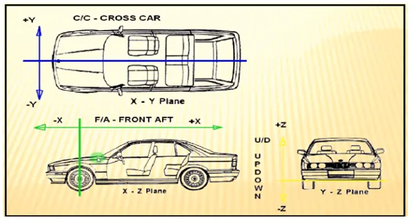
These datum schemes provide a reference system for all part surfaces and features using body coordinates. The figure below illustrates a typical body coordinate system. This system replaces the traditional X, Y., and Z directional designations with fore/aft 00, in/out (Y), and up/down or high/low (Z). The 0.0.0 point of the car is the front, lower, and center position
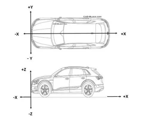
. X= Longitudinal direction [Fore & After- F/A] or [Front 'O' Line - FOL].
. Y Transverse direction [Cross Car-C/C] or [Centre 'O' Line].
. Z Vertical direction [Up & Down - U/D] or [Bottom 'O' Line].
- The origin of the body coordinate system (OX) is defined at the front center of the vehicle. It indicates the length
- The coordinate system (OZ) below its underbody indicates the height of the car.
- The coordinate system (OY) is its starting point is the center of the car body indicates the width of the car.
. The origin will have differed from carmakers to carmakers. Of the car.
7. Elaborate Body plane system & its essentials.
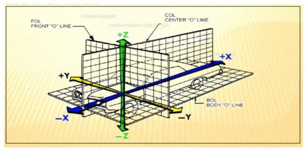
Body planes are the reference plane in an automotive car. These planes are used to define the GD&T of all car parts in an automotive
Body planes are three mutually perpendicular imaginary planes. These are generally considered to be present at the driver's position or sometimes at the engine location or the front end of the car depending on the customer.
The measurements from the body planes to the parts are called body line dimensions.
These body planes are called as
FOL Front "O" line.
COL Centre "O" line
BOL Body "O' line
The measurement along FOL or X-axis is called as F/A Front aft.
The measurement along COL or Y-axis is called a C/C Cross car.
The measurement along BOL or Z-axis is called U/DUP down.
In the below figure origin is somewhere below the driving sheet as it depends or changes from customer to customer. But axis system is commonly the same
Bodyline dimensions are essential for the reasons stated below,
- It defines the exact position of each product in the vehicle w.rt. a fixed origin.
- It ensures flawless design for assembly.
- While designing lines, all the designs are carried out relative to the bodyline, viz, fixture, turntable, etc.
- It assists in the easy location of different parts in a vehicle.
. It aims in creating a standardized system.
- It assists in quality checks.
These are the basic essential things that the body line dimension would help in BIW. It could help in designing lines like welding lines, assembly lines, or car bodies through fixtures & turntables, etc. This helps in designing every tool. Particular assembly or parts are designed w.r.t body lines or an axis system or car line also helps in quality while doing CMM of that system. CMM is basically done with the help of coordination. It has related particular fixture with that car part, because that dimension, coordinates of hole & pin should match so it will help in quality check also. We just give coordinates that belong to that hole both coordinates should match. With this matching means quality is approved. Below figure shows
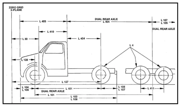
The below fig shows the use of an X-plane to define the length of the car
Below Fig Show the use of Y-Plane to define the width of the car.
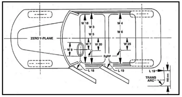
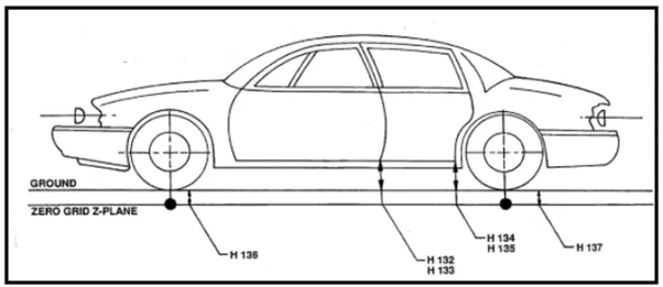
Below Fig Show the use of Z-Plane to define the width of the car.