Week 2:- BiW Fixture Basics Challenge
1.What is the process of project execution activity?
Project activities are those basically are being processed or being practiced in general project of BIW begins. Project activities are task from start to end of project. There are various steps involved in project. Below fig. show flow chart of project activities.
1. RFQ:
- RFQ – Request for Quotation.
- In this where the customer gives the requirement/specifications in detail for the given projects in the form of data or documents.
- Also, the customer specifies its technical offer, commercial offer, etc, how the project will be executed & the timeline of the project will be mentioned.
2. FIRST SPEC: DISCUSSION MEETING:
- In a project, the first specification discussion meeting typically involves stakeholders gathering to define and discuss the project's requirements, goals, and scope. It's crucial for aligning everyone's expectations and setting a clear direction for the project.
- After RFQ received, Technical offer, commercial offer, a timeline of the project, etc, will be discussed and prepared from outside.
- In this time required for data study, 3D design concept, simulation validation, quality check, 2d drawing release, bought-outs, manufacturing, assembly, installation & commissioning will be discussed and prepared in the technical offer.
- Based on the technical offer, the commercial offer will be finalized.
3. OFFER SUBMISSION:
- For an offer submission in a project context,typically compile and present a formal proposal detailing products, services, or solutions along with pricing, timelines, and any other relevant terms and conditions to a potential client or stakeholder. This is often done in response to a request for proposal (RFP) or as part of a competitive bidding process.
- After the finalization in the meeting, the offers will be submitted to the customer end. The customer will arrange to get an offer from other suppliers too.
- Based on the technical, cost, quality, standard, and name in the industries, the customer will be finalizing the offer.
4. LOI/PO RECEIPT:
•LOI stands for "Letter of Intent," which is a document outlining the preliminary understanding between two or more parties. It expresses a commitment to proceed with negotiations in good faith. PO stands for "Purchase Order," which is a commercial document issued by a buyer to a seller, indicating types, quantities, and agreed prices for products or services. A receipt is a document acknowledging that something has been received.
In the context of a project or business transaction, a receipt could be issued upon receiving a Letter of Intent (LOI) or a Purchase Order (PO) from a client or customer, confirming the receipt of their commitment to proceed with the project or purchase. This receipt serves as documentation of the transaction and can be used for record-keeping purposes.
•Schedule preparation in a project involves creating a timeline or plan that outlines the sequence of activities, milestones, and deadlines necessary to complete the project successfully. This process typically includes:
1. Identifying project tasks and activities: Break down the project scope into manageable tasks and activities that need to be completed.
2. Sequencing tasks: Determine the order in which tasks need to be executed, considering dependencies and constraints.
3. Estimating task durations: Estimate the time required to complete each task or activity, taking into account resources, dependencies, and other factors.
4. Allocating resources: Assign resources (such as personnel, equipment, and materials) to each task based on availability and requirements.
5. Developing a timeline: Create a timeline or schedule that outlines when each task will be started and completed, as well as key milestones and deadlines.
6. Reviewing and adjusting: Review the schedule to ensure it is realistic and achievable, and make adjustments as needed to accommodate changes or unexpected challenges.
By effectively preparing a schedule, project managers can better manage resources, track progress, and ensure that the project stays on track to meet its objectives and deadlines.
6. BOM PREPARATION:
BOM preparation is listing down of part list which includes bought out parts, vendor parts, and consumable items with qty. of each item. Through BOM preparation material budget will be fixed. B/O parts include motor, gear box, cylinder, pneumatic & hydraulic valves etc. Also vendor parts include all machined, fabricated parts etc. whereas consumable includes like oil, grease, glue, loctite etc.
7. DESIGN CONCEPT PREPARATION:
- Before design concept, we have to study the data of consumer requirements thoroughly which is carried out in design data study activities.
- During the design data study, we will proceed with rough sketches to get a flow while designing concepts.
- The concept preparation would include the process like load act on panels, clamping process, which spot should be welded first, travel of the gun.
- In this concept preparation, we should conceptualize the basic data like spot plan, cycle time, etc,
- The weld gun should not collapse while traveling, so by considering this have to make a concept preparation.
- To avoid collapses of weld guns or robots during traveling, a spot plan will be done at the initial stage.
- In design concept preparation, the design of the layout is been prepared at a very initial level which gives the information of placements of robots and fixtures.
- Spot plan should be taken into consideration during concept design preparation
- The spot plan clears us that how many robots are to be used and the sequence of the spot will be decided along with which robot will be cover certain spot places.
- Also, the cycle time should be considered while preparing the concept design. To calculate the cycle time, we should go to the cycle time study.
- Cycle time study includes min per shift, No. of shifts, No. of days per year, No. of component per year, the total number of minutes.
- Cycle time study includes min per shifts, no. of shifts, no of days per year, no of component per year, the total number of minutes, efficiency, Total no of seconds, take time seconds, average time per spot, total no of spot, no of robots placed. From the cycle time study, we can get time taken per spot, time is taken for a single component, efficiency of production. If the efficiency is not satisfied, we have to do some reconsideration in the design.
8. CUSTOMER APPROVAL:
- It is also known as the Design Approval Process (DAP).
- After design concepts, the customer will review the design concepts.
- If the design needs to be made simple or some other correction needs to be done in concept design will be discussed and after meeting the requirement of the customer, they will give approval to the design to go on with further activities.
9. DETAILING & DRAWING RELEASE:
- Once the customer approved the process, the detailing of the fixture parts which is to be manufactured has been done by giving appropriate dimensions and GD&T symbols.
- All the dimensions which are necessary for manufacturing should be included with GD&T in the drawing before releasing the drawing to the manufacturing team.
10. MANUFACTURING/BOP ORDERING:
- The mechanical & electrical parts like sensors, cylinders, etc, which needs for a fixture are ordered as per design specifications.
11. MECHANICAL / ELECTRICAL ASSEMBLY:
- After the materials ordered received to our end. The quality will check the working conditions and technical specs, which meets our requirement.
- After the quality check, the mechanical & electrical parts are assembled as per design.
12. QUALITY INSPECTION:
- After the assembly again the quality check is done.
- In all dimensions, positional accuracy, coordinates are checked using CMM.
13. INTERNAL TRIAL:
- After QC check, internal trials are made to check the operation of the fixture.
- It is the first trial taken in-house, so we will see by putting the assembly in the fixture whether the seating of assembly/panel suited correctly, whether the clamping operation is done properly, also whether the pins are getting into the holes, etc.
14. ONLINE TRIAL:
- The trail will be done automatically made through the control panel. The process sequence of operation is checked as by the designed way.
15. PACKAGING:
- To avoid damage, occur in the fixture while transportation which may also lead to affect the Aesthetic look & proper function of fixture packaging has been done.
- After the trials taken have to get the QC confirmation whether the panels met the standards/specs, given by the customer also whether the fixture meets the customer standards.
- After approval of QC, the packaging is been done as per standards. Certain companies follow certain packaging standards, So the packaging should be one as per customer standards.
16. DESPATCH:
- After the fixture has been packed for delivery as per standards. It’s been despatched to the customer.
17. INSTALLATION AS PER LAYOUT:
- As we discussed in design concept preparation, the design of the layout are been prepared at a very initial level which gives the information of placements of robots and fixtures.
- According to the design, the installation & commissioning team will install the fixtures.
18. TRAILS & TRAINING AT CUSTOMER:
- Production trials will be taken at the customer end.
- During the technical offer, we will be confirmed that the n-number of assemblies will be produced within 8hrs/12hrs shifts. So in customer trial, we have to achieve the confirmed quantity of assemblies.
- Once it is achieved training will be given to the operator, staff, engineers who involved in this process. The sequence of the working process by the fixture will be explained in detail.
- The checkpoints which have to be done after placing the panels into the fixture will be made clear to them.
19. BUYOFF MEETING:
- After trials and training at the customers' end, the buy-off meeting will be held.
- In this meeting customer will give reviews about the fixtures, sometimes a customer may need/feels better to do some additional work also. It will be discussed and finalize in the meeting.
20. FINAL HANDOVERS:
- The fixture and the documents support the fixtures/production will be handed over.
- Documents like clamp validation documents, ergo sheets, BOMs, charts will be delivered and handed over to customers. Documents will play a vital role in the industry. We should always have proof of our work done. The sequence of quality of work will be seen through the documents.
- Every automobile industry will follow some standards to maintain documents as per ISO, IATF.
- Now every automobile industry/vendor/supplier is maintaining the documents as per IATE (International Automotive Task Force).
- IATE – The international Automotive Task Force is a group of automotive manufactures which aims at providing improved quality products to automotive customers worldwide
2.What are the types of joining processes?
The durability and performance of any structure is largely depending on the quality & design of components joints. The whole structure can’t be made in one piece. Two fundamental options for joining material & components.
- Metallurgical joining
- Mechanical joining.
1. Metallurgical joining:
Metallurgical joining includes resistance welding,fusion welding, pressure welding and brazing/soldering which use different energies.
Resistance Welding
Resistance welding can be defined as; it is a liquid state welding method where the metal-to-metal joint can be formed within a liquid state otherwise molten state. It is a thermo-electric process in which heat is generated at the edge planes of welding plates because of electric resistance and a weld joint can be created by applying low-pressure to these plates. This type of welding uses electric resistance to generate heat. This process is very efficient with pollution free but the applications are limited because of the features like equipment cost is high, and material thickness is limited.
Types of Resistance welding
Different types of resistance welding are discussed below.
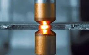
Spot Welding
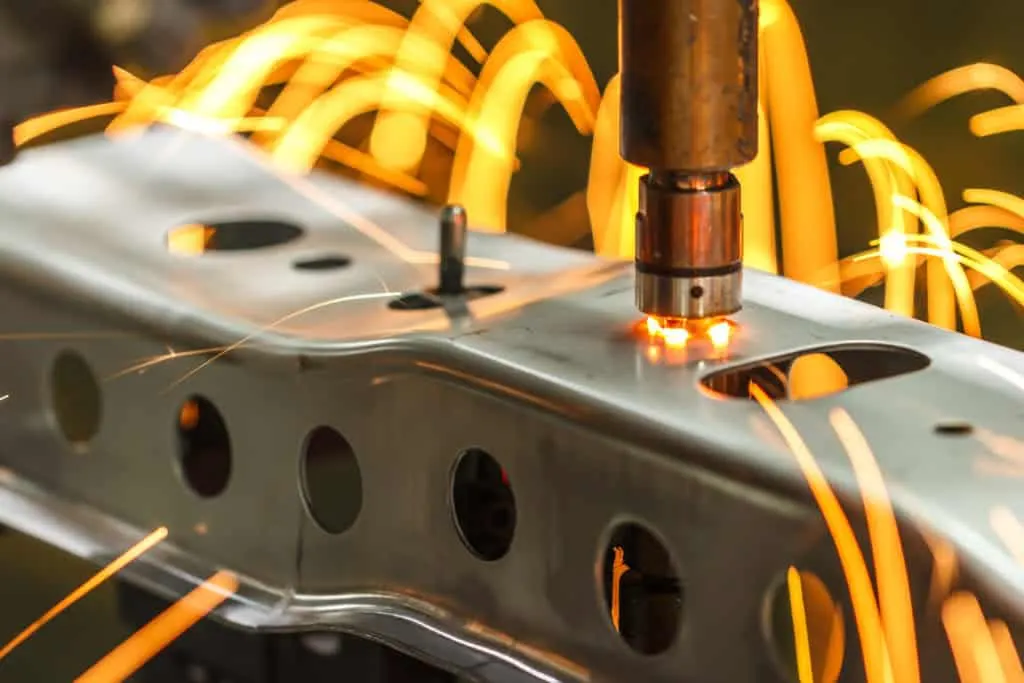
Spot welding is the simplest type of welding where the work portions are held jointly below the force of anvil face. The copper (Cu) electrodes will make contact with the work portion & the flow of current through it. The work portion material applies a few resistances within current flow which will cause limited heat production. The resistance is high at the edge surfaces because of the air gap. The current begins to supply through it, then it will reduce the edge surface.
The current supply & the time must be enough for the correct dissolving of edge faces. Now the flow of current will be stopped however the force applied with electrode continued for a second, whereas the weld quickly cooled. Later, the electrodes eliminate as well as get in touch with new spot to create a circular piece. The piece size mainly depends on electrode size (4-7 mm).
Seam Welding
This type of welding is also known as continuous spot welding where a roller form electrode can be utilized to supply current throughout work parts. Initially, the roller electrodes are getting in touch with the work part. High current can be supplied through these electrode rollers to melt the edge surfaces & shape a weld joint.
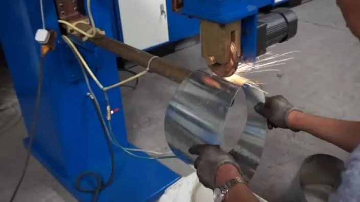
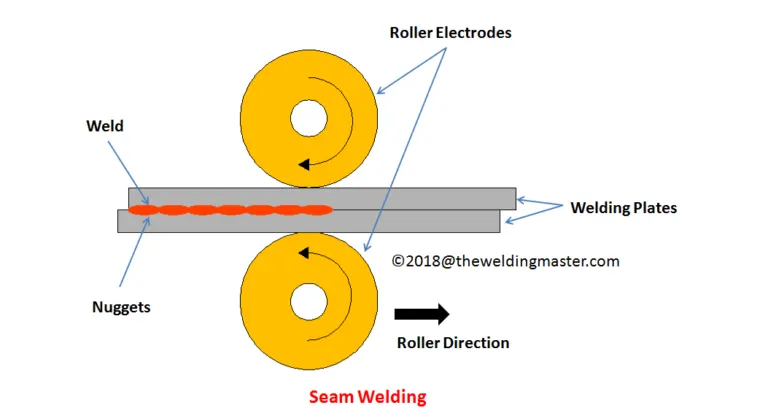
At present, the electrode rollers will begin rolling on work plates to make a permanent weld joint. The weld timing & electrode movement can be controlled to guarantee that the weld overlap & work part doesn’t acquire too warm. The speed of the welding can be about 60 in per min within seam welding, which is used to make airtight joints.
Projection Welding
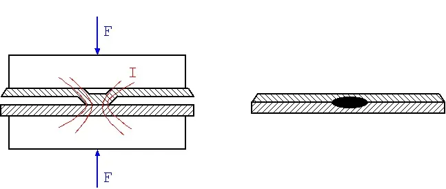
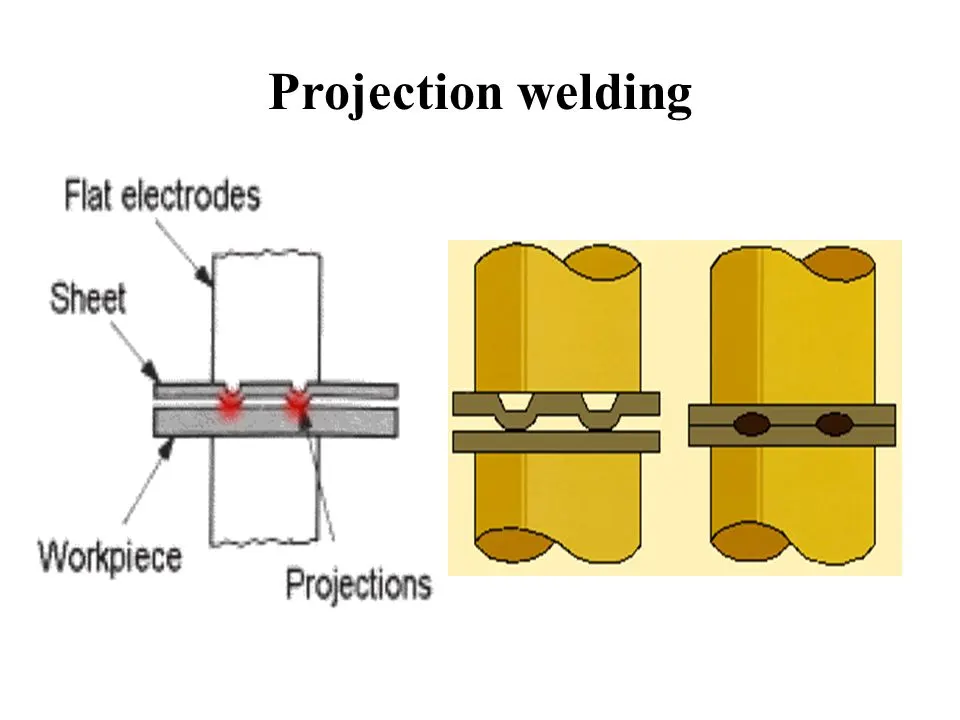
Projection welding is similar to spot welding apart from a dimple can be generated on work parts at the place wherever weld is preferred. At present the work parts held among electrode as well as a huge quantity of current flow through it. A little quantity of pressure can be applied throughout the electrode on welding shields. The flow of current throughout dimple which dissolve it & the force reasons the dimple level & shape a weld.
The advantages & disadvantages of resistance welding include the following
Advantages
- This method is simple and does not necessary high expert labor.
- The resistance welding metal thickness is 20mm, & thinness is 0.1 mm
- Automated simply
- The rate of production is high
- Both related, & different metals can be weld.
- Welding speed will be high
- It does not need any flux, filler metal & protecting gases.
Disadvantages
- Tools cost will be high.
- The work section thickness is limited because of the current requirement.
- It is less proficient for high-conductive equipment.
- It consumes high electric-power.
- Weld joints contain small tensile & fatigue power.
#1 MIG welding
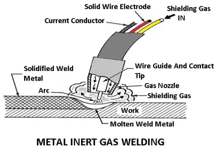
MIG welding holds for metal inert gas welding. This MIG welding process is also identified as gas metal arc welding (GMAW), which you can also call wire welding.
In this types of welding, a thin wire works as the electrode, which is fed from a spool attached to a gun through a flexible tube and comes out of the nozzle on the welding gun or torch. The wire is fed continuously when the trigger is pulled on the welding gun.
#2 TIG welding
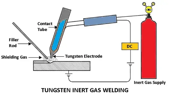
TIG welding stands for tungsten inert gas arc welding, from the American welding society, it is also identified as (GTAW). This welding process is likewise called gas welding.
TIG welding employs a tungsten electrode because tungsten has a high melting point. When we take the tig weld electrode gets hot, but it doesn’t melt we say that is a non-consumable electrode. Non-consumable electrodes do not mean that it does not last forever, but it does not melt and becomes part of the weld.
#3 Shielded Metal Arc Welding (SMAW)
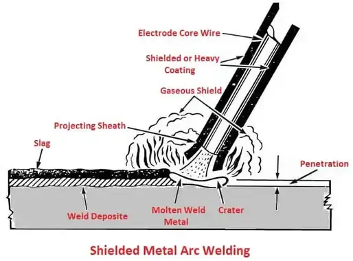
It is also identified as hand-operated metal arc welding, flux-shielded arc welding, or stick welding. In this type of welding process, in which the arc is struck between the metal rod or electrode (flux coated) and the workpiece, the surface of both the rod and the workpiece melt to create a weld pool.
The simultaneous melting of the flux coating on the welding rod will produce gas and slag, which shields the weld joint from the environment. Shielded metal arc welding is a process ideal for joining ferrous and non-ferrous materials with the thickness of the material at all positions.
Flux Cored Arc Welding (FCAW)
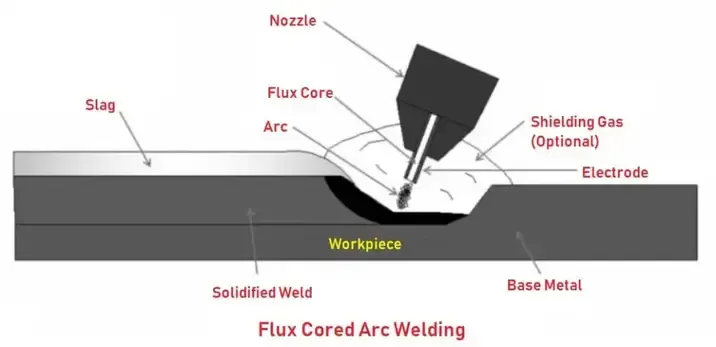
This type of welding is almost similar to MIG welding. In fact, MIG welders can often perform flux-cored arc welding. In this welding, the wire has a core of flux that forms a gas shield around the weld. This reduces the demand for external gas supply.
FCAW is better suited for rough, heavy metals because it is a high-heat welding process. It is usually used for heavy equipment repair for this purpose. It is a process that does not produce too much waste. Because there is no need for external gas, it also costs less.
Plasma arc welding (PAW)
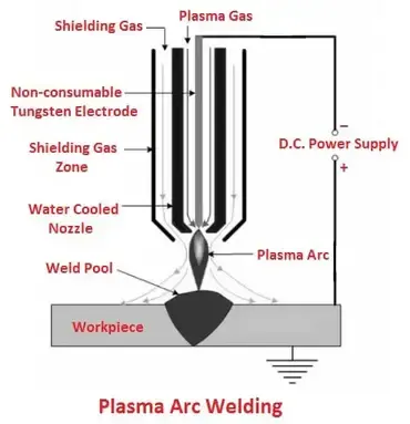
Plasma arc welding (PAW) is an arc welding process utilizing heat generated by a compressed arc between a tungsten non-consumable electrode and workpiece (transferred arc process) or water-cooled constricting nozzle (non-transferred arc process).
The plasma is a gaseous mix-up of positive ions, electrons, and neutral gas molecules. The transferred arc process creates plasma jets of high energy density and can be used for high-speed welding and cutting ceramics, copper alloys, steels, aluminum, nickel alloys, and titanium alloys.
Electron beam welding
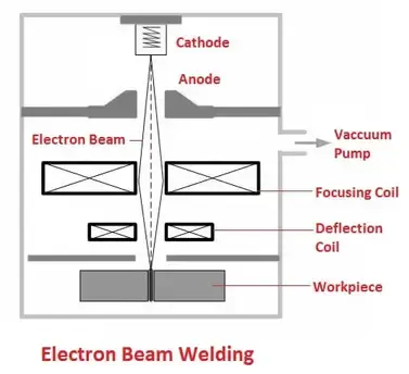
Electron beam welding is a welding process that applies the heat created by a beam of high-energy electrons. The electrons hit the workpiece, and their kinetic energy is converted into thermal energy, heating the metal so that the edges of the workpiece can be connected and a weld is formed after freezing.
EBM is also a liquid state welding process. The metal-to-metal joint is made in a liquid or molten state. It is also described as a welding process because it accepts electron’s kinetic energy to join two metal workpieces.
Laser Beam Welding (LBW)
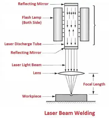
Laser Beam Welding (LBW) is a welding process in which heat is formed by a high-energy laser beam targeted on the workpiece. The laser beam heats and melts the ends of the workpiece, making a joint.
In laser welding (LBM), the joint is formed as a sequence of overlapped spot welds or as a continuous weld. Laser welding is employed in the electronics, communications, and aerospace industries, to manufacture medical and scientific equipment incorporating small components.
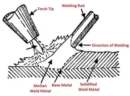
Gas welding is performed by melting the sides or surfaces connected by gas flame and providing the molten metal to flow together, thus creating a solid continuous joint upon cooling.
Oxygen-acetylene mixtures are used much more often than others and hold a prominent position in the welding industry. The temperature of the oxy-acetylene flame in its hottest area is about 3200°C, while the temperature reached in the oxy-hydrogen flame is about 1900°C.
2. Mechanical joining:
Mechanical joining is a process for joining parts through clamping or fastening using screws, bolts, or rivets. Advantages of mechanical joining include versatility, ease of use, and the option to dismantle the product in cases where regular maintenance requires it. The ability to join dissimilar materials is another benefit. A drawback of using mechanical joining is the lack of a continuous connection between parts because the joint is achieved through discrete points. Also, holes created for joining are vulnerable to fractures and corrosion.
Mechanical joining – also called joining by forming – has become interesting for the automotive industry due to the request to reduce fuel consumption and thereby emissions. To reduce weight on the car body, the usage of lightweight materials in the body-in-white application has increased. This includes aluminum, high-strength steel alloys, polymers, and composites. Here the different types of mechanical joining become important. All mechanical joining methods are cold forming techniques. One general benefit for all mechanical joining methods is the mobility of the material after joining. At the same time, mechanical joining offers an impressive strength.
a)Mechanical fastening:
The joining of material combinations which cannot be easily welded such as pre-painted steel or very dissimilar metal. Ex. AI application in autobody makes use of mechanical fastening to overcome the poor inherent weldability of AI.
The joining of materials in applications where high fatigue life is critical compared to static strength.
The joining of materials where high tool life is of relative importance
E.g. screw, bolts, etc
b) Self-piercing riveting:
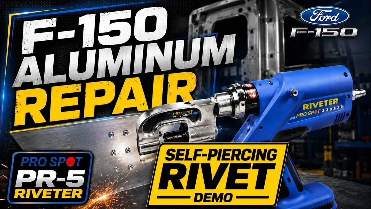
Self-piercing riveting is high-speed mechanical fastening for point joining sheet material, typically steel & aluminum alloys. It is a single-step technique generally using a semi-tubular rivet to clinch the sheet in the mechanical joint. There is also a process variant that utilizes solid rivets.
As the name suggest pre-drilled hole are not required, allowing the joint to be made rapidly in one operation. The process cycle is shown in the cross-section below.
c. Hemming & seaming process:
Hemming & seaming are two similar metalworking processes in which a sheet metal edge is rolled over onto itself. Hemming is a process in which the edge is rolled flush to itself, while the seam joins edges of two materials. Hems are commonly used to reinforce an edge, hide burrs and rough edges, and improve appearance. Seams are commonly used in the food industry on canned goods, amusement park cars, metal roofing (with a roof seamer), and in the automotive industry. The process for both hemming and seaming are the same, except that the tonnage requirement is greater for seaming. The process starts by bending the edge to an acute angle. A flattening die is then used to flatten the hem. The below figure illustrates hem formation.
3.What is Resistance Welding & its application in the automotive sector?
Resistance welding can be defined as; it is a liquid state welding method where the metal-to-metal joint can be formed within a liquid state otherwise molten state. It is a thermo-electric process in which heat is generated at the edge planes of welding plates because of electric resistance and a weld joint can be created by applying low-pressure to these plates. This type of welding uses electric resistance to generate heat. This process is very efficient with pollution free but the applications are limited because of the features like equipment cost is high, and material thickness is limited.
Types of Resistance welding
Different types of resistance welding are discussed below.
Spot Welding
Spot welding is the simplest type of welding where the work portions are held jointly below the force of anvil face. The copper (Cu) electrodes will make contact with the work portion & the flow of current through it. The work portion material applies a few resistances within current flow which will cause limited heat production. The resistance is high at the edge surfaces because of the air gap. The current begins to supply through it, then it will reduce the edge surface.
The current supply & the time must be enough for the correct dissolving of edge faces. Now the flow of current will be stopped however the force applied with electrode continued for a second, whereas the weld quickly cooled. Later, the electrodes eliminate as well as get in touch with new spot to create a circular piece. The piece size mainly depends on electrode size (4-7 mm).
Seam Welding
This type of welding is also known as continuous spot welding where a roller form electrode can be utilized to supply current throughout work parts. Initially, the roller electrodes are getting in touch with the work part. High current can be supplied through these electrode rollers to melt the edge surfaces & shape a weld joint.
At present, the electrode rollers will begin rolling on work plates to make a permanent weld joint. The weld timing & electrode movement can be controlled to guarantee that the weld overlap & work part doesn’t acquire too warm. The speed of the welding can be about 60 in per min within seam welding, which is used to make airtight joints.
Projection Welding
Projection welding is similar to spot welding apart from a dimple can be generated on work parts at the place wherever weld is preferred. At present the work parts held among electrode as well as a huge quantity of current flow through it. A little quantity of pressure can be applied throughout the electrode on welding shields. The flow of current throughout dimple which dissolve it & the force reasons the dimple level & shape a weld.
The advantages & disadvantages of resistance welding include the following
Advantages
- This method is simple and does not necessary high expert labor.
- The resistance welding metal thickness is 20mm, & thinness is 0.1 mm
- Automated simply
- The rate of production is high
- Both related, & different metals can be weld.
- Welding speed will be high
- It does not need any flux, filler metal & protecting gases.
Disadvantages
- Tools cost will be high.
- The work section thickness is limited because of the current requirement.
- It is less proficient for high-conductive equipment.
- It consumes high electric-power.
- Weld joints contain small tensile & fatigue power.
Applications
Resistance spot welding (RSW) is a widely used welding technique in the automotive and aeronautical industries. Here are some key points about its applications in the automotive sector:
-
Body-in-White Assemblies: RSW is commonly used to join various parts of the car body, ensuring structural integrity and stability.
-
Air Reservoirs: In air brake systems, RSW is employed to create leak-proof welds in air reservoirs.
-
Oil Pans: RSW helps assemble oil pans, which are critical components for lubricating the engine.
-
Shock Absorbers: RSW is used to join components of shock absorbers, ensuring their functionality and safety.
-
Exhaust Systems: RSW plays a role in assembling exhaust systems, which need robust and durable welds to withstand high temperatures and vibrations.
4.What is fusion welding & types of fusion welding with its application in the automotive sector?
Fusion welding involves joining two or more objects by heating. When performing fusion welding, one could use filler materials, depending on the work’s nature. Welders do not apply external pressure when joining the parts.
Fusion welding is different from non-fusion welding. Non-fusion welding takes place under low heat intensity. During this process, the base metal does not undergo any melting process. Welders do not use filler materials when performing non-fusion welding. The best examples of non-fusion welding include soldering, pressure, and brazing welding.
Types of Fusion Welding Processes
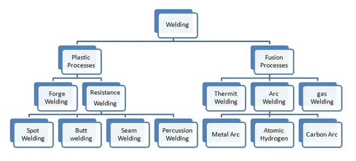
After finding the full definition of fusion welding, it is crucial to understand fusion welding types. The different types of fusion welding are categorized based on the heat source. below are some of the main types of fusion welding:
Arc Welding
Fusion arc welding is the most common type of fusion welding. Arc welding involves connecting two or more parts using an electric art. The electric arcs produce high levels above 6000 degrees Fahrenheit using the machines like YESWELDER Digital MIG-205DS MIG welder. This feature makes fusion arc welding ideal for joining hard materials. Welders can also perform arc welding underwater. The most common types of arc welding include:
Shielded metal arc welding is used for welding ferrous and non-ferrous materials regardless of the position.
Tungsten inert gas welding uses non-consumable tungsten to create the arc between the electrode and the base plate. The TIG welders for aluminum use an inert shielding gas to prevent contamination and oxidation.
Metal gas arc welding involves the formation of an electric arc between the wire electrode and the material using the MIG welders. The use of shielding gas prevents contamination.
Submerged arc welding is the method that involves using flux and a consumable electrode. The flux prevents the sparks and spatters and conducts electricity while in the molten state.
Plasma arc welding involves the formation of an electric arc between the nozzle and the electrode. The electric arc ionizes the argon gas found in the chamber.
Flux cored arc welding is an alternative to shielded Metal Arc Welding. The whole process involves feeding consumable electrodes with flux using the flux core welders for the thickest metals.
Gas Welding
This process involves using a blowpipe held in the hand that combines both oxygen and acetylene gas to produce a flare. It is a solvent-based fusion welding that requires a flame to meltdown and connects the surface. Oxygen acts s the primary fuel source for the flame.
This welding type bases its foundation that there must be oxygen to produce fire. The oxygen allows it to create an extremely hot flame that surpasses 4500 degrees Fahrenheit.
High Energy Welding
High energy welding is a type of fusion welding that uses light radiation to produce heat. Welders blast the radiation on the material’s surface, turning them into a molten state. The two pieces will join once they cool down. The two types of high-energy fusion welding include:
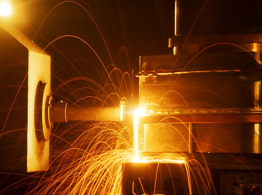
Electron Beam Welding
This high-energy welding uses high-velocity electrons to join two different materials. The process takes place under normal atmospheric pressure, and the electrons produce heat in the material as they enter. The welts are mostly deep and narrow.
Laser Beam Welding
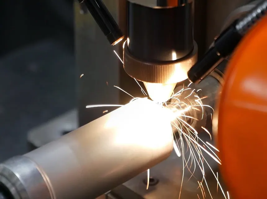
Laser beam welding utilizes a laser beam as the primary source of heat. The use of the laser beam helps maintain a highly focused energy source that is used to join different metal pieces of plastics. It uses light energy to produce heat. The rig produces dissipated light that warms the surface with every single blast.
Resistance Welding
Resistance welding is one of the fastest fusion welding types. The speed makes it best for use in the automotive industry.
This type of resistance welding involves creating a persistent joint with alternating nuggets. It uses shifting disks to replace the traditional spot welding electrodes as the process goes on.
Applications of Fusion Welding
Several processes involve the use of fusion welding. Structural engineers use fusion welding when manufacturing large structures such as:
Airplanes
Bridges
Ships
Pressure vessels
Welded pipes
Shielding explosives
Since it produces high heat levels, one can use fusion metals to combine different materials regardless of their thickness. Some of the main applications include:
Joining Metals
Fusion welding involves using high heat levels in joining two or more separate parts. Unlike soldering, fusion welding melts the base metal and may require a filler material to make a joint. High heat exposure turns the metal part into a molten state. These parts join together to form a weld bead as it cools down. The result is always stronger than the base material.
When joining metals, one may need to exert pressure to make welds with a heat source. When joining two metals, shielding gas helps prevent the filler material or joint from contaminating or oxidizing.
Joining Plastics
Fusion welding is also applicable when joining plastics. Solvent welding uses adhesives instead of heat. Joining plastics using fusion welding takes place in 3 states which include;
Preparing the surfaces by cleaning and drying
Applying heat and exerting pressure on the molten part.
Cool down the molten parts to create a strong bond between the two plastics. The process might require a cooling room. However, this may not be important since the process is also fast.
In the context of the automotive sector, fusion welding plays a crucial role in creating strong and durable connections between various components. Let’s explore some of its applications:
- Roofs, Window, and Door Openings: Fusion welding is commonly used to join metal parts in the construction of car roofs, window frames, and door openings. These welds ensure structural integrity and weather resistance.
- Exterior Panels: Automotive body panels, such as fenders, hoods, and doors, are often fusion-welded. The welds provide a seamless appearance and maintain the overall strength of the vehicle.
- Exhaust Systems: Fusion welding is essential for joining exhaust pipes, mufflers, and catalytic converters. These components must withstand high temperatures and corrosive gases, making robust welds crucial.
- Chassis and Frame: Welding techniques are used extensively in assembling the chassis and frame of vehicles. Proper fusion welds ensure stability, safety, and load-bearing capacity.
- Suspension Components: Fusion welding is employed to connect suspension arms, control arms, and other critical components. These welds withstand dynamic forces during vehicle operation.
- Fuel Tanks: Welding is crucial for fabricating fuel tanks. Properly welded seams prevent leaks and ensure fuel containment.
- Transmission and Engine Mounts: Fusion welding secures transmission and engine mounts to the vehicle’s frame. These welds absorb vibrations and maintain alignment.
- Roll Cages: In high-performance and racing cars, roll cages are fusion-welded for occupant safety during accidents or rollovers.
- Spot Welding: A specific type of fusion welding called spot welding is commonly used to join sheet metal parts in automotive assembly lines. It creates localized welds at specific points, ensuring efficient production.
- Repair and Maintenance: Fusion welding is also essential for repairing damaged automotive components. Whether fixing a cracked exhaust pipe or reinforcing a damaged frame, skilled welders play a vital role.
5.What is the 3-2-1 principle?
The 3-2-1 principle is a fundamental concept used in jig and fixture design.
-
Locating Principle:
- The 3-2-1 principle is also known as the six-pin or six-point location principle.
-
Clockwise around X-axis (CROT-X)
Anticlockwise around X-axis (ACROT-X)
Clockwise around Y-axis (CROT-Y)
Anticlockwise around Y-axis (ACROT-Y)
Clockwise around Z-axis (CROT-Z)
Anticlockwise around Z-axis (ACROT-Z)
- It provides a systematic way to position and secure a workpiece within a fixture.
- The goal is to restrict the degree of freedom of the workpiece, ensuring it stays in the desired position during machining or assembly.
-
How It Works:
- Imagine a rectangular workpiece with three axes: X-axis, Y-axis, and Z-axis.
- The 3-2-1 principle achieves this by using a combination of pins and external forces:
- Three adjacent locating surfaces of the workpiece rest against 3, 2, and 1 pin, respectively.
- These pins prevent 9 degrees of freedom (movement along the three axes and rotation).
- The remaining three degrees of freedom are arrested by external clamping forces.
- These forces are usually provided directly by clamps.
- Three adjacent locating surfaces of the workpiece rest against 3, 2, and 1 pin, respectively.
-
Methodology:
- Let’s break it down step by step:
- The workpiece rests on three pins (A, B, and C) inserted in the base of the fixture.
- This prevents rotation about the X-axis and Y-axis and downward movement.
- Two additional pins (D and E) are inserted in a plane perpendicular to the one containing pins A, B, and C.
- Now rotation about the Z-axis and leftward movement is restricted.
- Finally, pin F in the second vertical face of the fixture arrests the ninth degree of freedom.
- The workpiece rests on three pins (A, B, and C) inserted in the base of the fixture.
- Let’s break it down step by step:
-
Summary:
- A workpiece is completely confined when it is blanked against:
- Three points in one plane (3 locators on the primary locating surface).
- Two points in a plane perpendicular to the first one.
- One point on a plane mutually perpendicular to the first two planes.
- A workpiece is completely confined when it is blanked against:
6.Define Body coordinate system?
The body coordinate system has been widely used in the automotive industry for the drawing of body parts, and product & process design. A coordinate system is a reference system consisting of a set of points, lines & surfaces, used to define the positions of points in space in either two or three dimensions. In general, BCS is also called a car line & body line.
Car lines are the (grid lines) shown on the fixture, which virtually represent the same location in BIW. All the car line on the fixture displays the coordinate at the corner for reference. With these lines, one can easily relate the location in BIW.
Sometimes a single coordinate hole is given in the fixture that also represents the car line coordinates, from that reference point fixture is made & can be inspected. Body coordinates are mentioned near the hole. The below figure shows the car line on the fixture.
Automotive sheet metal components are designed in CAD (Computer-aided Design) software e.g. CATIAv4-v5, UG, ProE, and Ideas, In any cad tool, there is a default axis system X, Y, Z.
Lets us consider if every designer starts the design of the BIW Door Assembly part with a default axis system, then it will be difficult to assemble or position the part with respect to each other.
Due to avoid this issue, BIW car panels are designed with reference to car axis means at their Original position of the final car built.
The reference axis system of the software is used for the design of the various features of the parts (e.g. hole, fillet, threads,) To correlate the position of all the automotive components during the final assembly the axis system of the vehicle is used. Most of the time vehicle axis systems and software axis systems are the same. e.g. In most European OEMs, The X-axis represents the length of the vehicle Y-axis represents the width of the vehicle Z-axis presents the height of the vehicle. Y-axis is considered to be located at the front axle. All BIW welding fixtures are designed with reference to the car line
These datum schemes provide a reference system for all part surfaces and features using body coordinates. The figure below illustrates a typical body coordinate system. This system replaces the traditional X, Y, and Z directional designations with fore/aft (X), in/out (Y), and up/down or high/low (Z). The 0,0,0 point of the car is the front, lower, and center positions.
VEHICLE ORIENTATION:
All vehicle product drawings are identified numerically relative to the three vehicle planes described and shown below.
X= longitudinal direction (fore & after-F/A) or (Front O line-FOL). Y= transverse direction (Cross car-C/C) or (Centre O line-COL).
Z= Vertical direction (Up & down- U/D) or (Bottom O Line-BOL).
The origin of the body coordinate system (OX) is defined at the front center of a vehicle. It indicates the length of the car & the coordinate system (OZ) is below its underbody indicates the height of the car & the coordinate system (OY) whose starting point is the center of the car's body indicates the width of the car.
Maintaining X, Y & Z coordinates in the fixture is a very important factor.
We should try that the coordinates of locating & clamping points should not be in three decimal (e.g. X=100.124, Y=245.127, Z=450.458)
They should be in the whole nos or max up to 1 decimal. Once these coordinates are maintained automatically the BIW base structure is maintained.
7.Elaborate Body plane system & its essentials.
Body planes are the reference plane in an automotive car. These planes are used to define the GD & T of all car parts in the automotive domain.
Body planes are three mutually perpendicular imaginary planes. These are generally considered to be present at the driver position or sometimes at the engine location or at the front end of the car depending on the customer.
The measurements from the body planes to the parts are called body line dimensions.
These body planes are called as
FOL Front “O” line.
COL Centre “O” line
BOL Body “O’ line
The measurement along FOL or X-axis is called a F/A Frontaft.
The measurement along COL or Y-axis is called a C/C Cross car.
The measurement along BOL or Z-axis is called U/DUP down.
In the below figure, the origin is somewhere below the driving sheet as it depends on or changes from customer to customer. But the axis system is commonly the same.
Bodyline dimensions are essential for the reasons stated below,
It defines the exact position of each product in the vehicle w.r.t. a fixed origin.
It ensures flawless design for assembly.
While designing lines, all the designs are carried out relative to the bodyline, viz, fixture, turn table, etc.
It assists in the easy location of different parts in a vehicle.
It aims in creating a standardized system.
It assists in quality checks.
These are basic essential things that body line dimension would help in BIW. It could help in designing lines like welding lines, assembly lines, or car bodies through fixtures & turntables, etc. This help in designing every tool. Particular assemblies or parts are designed w.r.t body lines or an axis system or car line also helps in quality while doing CMM of that system. CMM is basically done with the help of coordination. It has related to a particular fixture with that car part because the dimension and coordinates of the hole & pin should match so it will help in the quality check also. We just give coordinates that belong to that hole both coordinate should match. With this matching means quality is approved. The below figure shows some examples.
Fig show the use of the X plane to define the length of the car.
Below figure show the use of the Y plane to define the width of the car.
The below figure shows the use of the Z plane to define the height of the car.