Wiring harness design in CATIA V5 - 3D modeling Week 2 Challenge
AIM - Define given connectors & Connector clip as Electrical Connector using Electrical Part design Workbench in CATIA V5
OBJECTIVE - The objective of the project is to first , download the given files from TE.com then define them as an electrical connector or equipment & lastly give all the required electrical properties to them using the electrical Part design Workbench on CATIA V5
These are steps required to do this project
- Create the required geometrical parameters for connector
- Create bundle entry point
- If connector accommodates clip then define a geometrical parameter for the clip
- Define part as connector or mounting equipment
- create bundle connection point
- create a connector connection point
- create a cavity connection point if there is a clip
CONTENT -
There are two connectors ,one with clip attachment feature (Tyco 174357-2) and the other one is without it(Deutsch DT06 – 08SA). the third part is the clip (Tyco 85229-1)
CONNECTOR 1 - Without clip attachment- Deutsch DT06 – 08SA
Figure 1 - The fig 1 shows that given connectors is defined as Electrical Connector 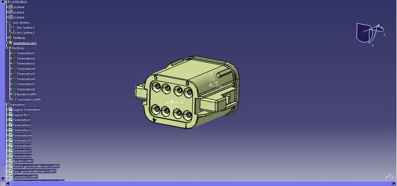
Figure2- the figure2 shows that operations done to define electrical connector
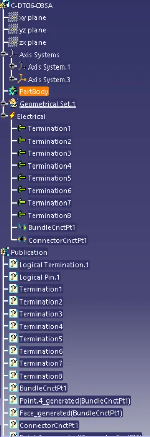
CONNECTOR 2 - With clip attachment (Tyco 174357-2)
Fig3 - It shows that connector(Tyco 174357-2) is defined as electrical connector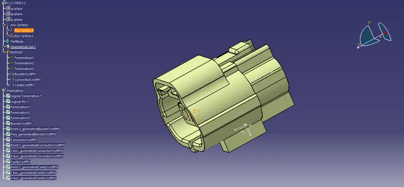
CLIP (Tyco 85229-1)
Fig4 - It shows that given part (Tyco 85229-1) is defined as equipment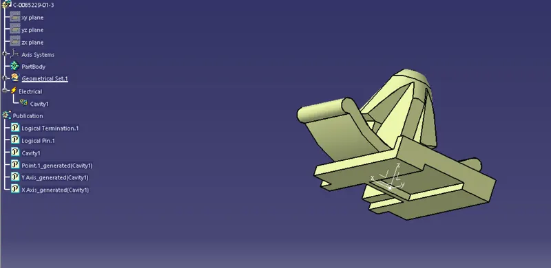
CLIP & CONNECTOR ELECTRICAL ASSEMBLY
Fig5-it shows the assembly of clip&connector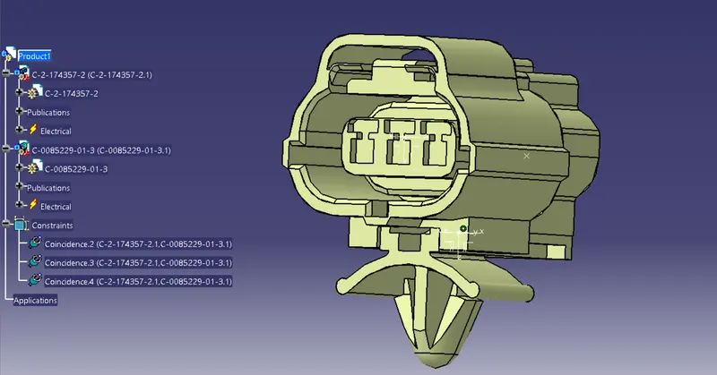
CONCLUSION - Both the connectors & the clip were defined as an electrical connector & electrical mounting equipment respectively, All the necessary properties to Connectors & Clip were given.