Week 2:- BiW Fixture Basics Challenge
- Process of Project execution
RFQ Received:
This is the project's initial stage. Request for Quotation is referred to as RFQ. The client provides data or papers that describe the requirements or specifications in detail for the assigned project. Also, the customer requests a quote for the entire project and provides technical offers, commercial offers, a timeframe, and other information.
- 1st Spec Discussion Meeting:
Several parameters, including 3D Design idea, analysis of design, simulation validation of design, quality check, 2D drawing release, manufacturing, assembly installation, and commissioning, will be used to analyze the whole data of the project. The final quotation is then presented to the customer after taking the cost of the entire procedure and time for execution into account.
- Offer Submission:
The customer's bids will be submitted following the meeting's conclusion. The customer will be finalizing the offer based on the Technical Cost, Quality, Standard, and Brand Name of the Industry.
- LOI/PO receipt:
Customers are not limited to requesting quotes from a single business; instead, they will request quotes from several businesses, evaluate those quotes, and then select the business that best matches their needs. They will then submit a PO (Purchase Order) to that business. The business should begin working on the project as soon as it receives a PO from the client.
- Schedule preparation:
The project begins by creating a timeline of the project to be finished by the deadline as soon as the PO is received from the customer. It is created by considering concepts like design data analysis, 3-D design, simulation validation, manufacturing, assembly, BOM release, finishing, installation, trial run, and quality check. Later, the schedule is created by allotting time to certain procedures for specific personnel and allocating shifts in accordance with taking unplanned circumstances (if the process is not completed in the allocated time) into consideration.
- BOM preparation:
A bill of materials (BOM) includes a detailed list of all the raw materials, assemblies, subassemblies, parts, and components that are required to make a product, in addition to the quantities required for each.
- Design Concept Preparation:
We must research the facts on consumer requirements based on the information provided by the client. By examining every necessity, the general flow of the design process can be assumed as rough drawings of the Component and every one of its sub-assemblies are created. It is created by considering the force exerted on the component, the different joining processes, the avoidance of interference from tools, the kind of weld, the spot plan, the joining location, and the duration of each operation. When creating a design idea, the layout's design is created at a very basic level and contains details about future robots and fixtures.
- Customer Approval:
Once the Fixture design is completed and meets all the customer's requirements, the customer will be contacted to review and provide any necessary corrections. The team will make the required corrections, and once the customer is satisfied, they will give their final approval to proceed with the project.
- Detailing & Drawing Release:
Once the design is approved by the customer, the design team will provide the manufacturing team with a comprehensive 2D drawing. This drawing will include all the necessary parts with their specific dimensions for the manufacturing process.
- Manufacturing/BOP Ordering:
The mechanical and electrical components, such as sensors and cylinders, necessary for producing the product, are procured based on the design specifications.
- Mech/Elec. Assy:
Once all the components have been received, a quality control inspection will be conducted in accordance with the specified criteria. Subsequently, mechanical, or electrical assemblies will be prepared based on the provided design.
- Quality Inspection:
Once all the components are reassembled, a quality check is conducted by utilizing the CMM machine to verify dimensions and positioning.
- Internal Trial & Testing:
Once the quality control inspection is complete, internal tests are conducted to verify that it functions according to the specified criteria. To achieve this, a simulated version of the design is utilized prior to the actual project implementation. This particular fixture is evaluated based on its clamping, welding, and workpiece positioning capabilities.
- Online Trail:
Once the internal trial and testing phase is completed, the online trial will be conducted. During this stage, the fixture will function automatically using electrical connections. The online trial will be executed under customer observation in order to obtain customer approval based on the specified design requirements. The process sequence of operations will be thoroughly examined according to the design specifications.
- Packaging:
To minimize harm to the fixture during transportation, packaging is carried out for various assemblies. Once quality control has been approved, packaging is conducted according to established guidelines.
- Dispatch:
Once the product has been appropriately packaged, it is prepared for shipment. The layout design is conducted during the early stages, considering the functionality, operation, process, and sequence requirements. The installation of various assemblies is carried out in accordance with the layout design.
- Trials & Training:
The customer will participate in production trials, where the company team will manufacture the necessary number of components using our products based on the technical offers provided by the company initially. After successfully achieving the desired result, both the employees and engineers involved in the process will receive comprehensive training, explaining the step-by-step procedure in detail.
- Final Handover:
The relevant paperwork pertaining to the fixture will be transferred to the customer. The customer will receive the documents for clamp validation and design.
- Types of Metal Joining Processes
Metals can be joined using heat, pressure and chemical reactions depending upon the method to be employed. The joint is developed through (a) metallurgical continuity (through fusion and diffusion), (b) mechanical interlocking and (c) chemical/physical forces.
- Mechanical joining: components to be joined are held together using suitable force with the help of nuts and bolt, and rivets.
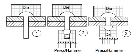
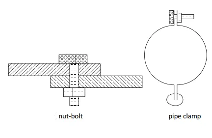
Fig. Example for Mechanical Joining - Riveting Fig: Nut, bolt and pipe-clamp
- Fusion: Joining of components by this mechanism is primarily based on fusion/melting of faying surfaces of the components to be joined using suitable heat source. Heat may also be used for melting filler metal or electrode depending upon the type of joining process. Additionally, molten metal produced during joining is subjected to (a) interaction with gases (oxygen, nitrogen, hydrogen) present in vicinity of molten pool and (b) solidification. Interaction of the atmospheric gases with molten pool (if not protected properly) leads to inclusion and porosity in the joint, while unfavorable solidification can lead to solidification cracking, shrinkage porosity and coarse grain structure.
- Fusion Welding: Welding generally uses localized heating during common fusion welding processes (shielded metal arc, submerged arc, gas metal arc welding, etc.) for melting the faying surfaces and filler metal.
- Resistance Welding: The welding processes in which heat required for thermal softening or partial melting of base metal is generated by electrical resistance heating followed by application of pressure for consolidation to develop a joint are grouped as resistance welding processes. Spot welding and seam welding are the most common resistance welding processes.
- Solid State Welding: The solid-state welding processes are those in which weld joint is developed mainly by application of pressure and heat through various mechanism such as mechanical interlocking, large scale interfacial plastic deformation and diffusion. Examples include Ultrasonic welding, Cold pressure welding, Explosion welding.
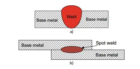
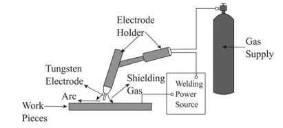
Fig: representation of resistance welding fig: Representation of fusion welding
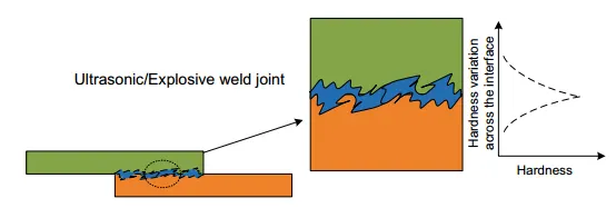
Fig: Solid state Welding
- Chemical Joining: The typical joining methods where joining is realized through chemical reactions and intermetallic formation at the joint interface include adhesive joining and low melting point brazing and soldering. However, joints developed using chemical reaction-based mechanism usually suffer from limited joint strength and applicability in specific environment and unsuitable for high temperature conditions.
- Adhesive joining: Adhesive joining involves application of suitable chemical mixture on the cleaned faying surfaces which after curing offers required peak joint strength. Chemical reactions like cross-linking polymerizations in adhesives and at adhesive–metal interface during curing provide high joint strength. However, application of adhesive joining is limited by low stability of adhesive at high temperature and in wet environment.
- Brazing and Soldering: The joint by brazing, soldering and brazing welding is primarily developed using comparatively low melting point filler metal than base metals. The base metals are heated to a temperature high enough to facilitate melting of filler metal but significantly less than melting temperature of base metals.
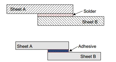
Fig. Soldering and Adhesive joining
- Plastic Deformation:
Macro-plastic deformation: Joining processes like riveting, clinching and friction stir welding (FSW) using macro-scale plastic deformation involve flow of the metal from one zone to another to obtain a joint continuity. The macroscopic plastic deformation in case of riveting and clinching is primarily used to give the desired shape to joining members to achieve mechanical interlocking (Fig. 1.9), while in case of other macroscopic plastic deformation-based joining processes like FSW, friction welding, etc., a metallurgical joint is created.
b. Micro-Plastic deformation: The micro-scale plastic deformation at interface can be used for joining of both thin sheets and thick plates using joining processes like ultrasonic welding and explosive welding. The extent of flow of metals from the faying surfaces into each other (to cause mechanical and metallurgical bonding) during joining is determined by yield strength and ductility of the components being joined and force applied to facilitate interfacial plastic deformation. Low strength and high ductility metals flow more than high strength and low ductility metal system at the joint interface.
- Resistance Welding and its application in automotive sector
1. Resistance Spot Welding:
A resistance welding method in which the welding current is concentrated at the faying surfaces of overlapping sheets by cylindrical copper alloy electrodes pressed on the outer surfaces. A force is applied to the electrodes to squeeze the parts together and a current pulse is passed. Force is maintained on the electrodes and may even be increased following the current pulse to consolidate the weld and prevent cracking or porosity. Electrodes become heated and are cooled by an internal flow of water. The process is used on many different materials over a wide range of thicknesses from fractions of a millimeter up to about 5mm or even more.
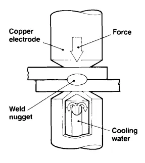
2.Resistance Seam Welding:
A resistance welding process in which overlapping sheets are gripped between roller electrodes enabling a series of either discontinuous or overlapping spots to be made. The force on the electrodes is sufficient to give good contact at the surface of the sheets and a fused nugget develops at the faying surfaces. Welding current is usually supplied in pulses with rotation being continuous but some use is also made of continuous current.
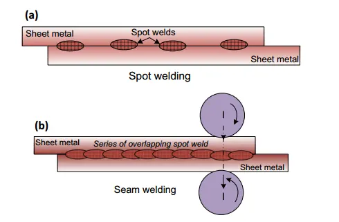
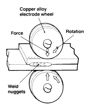
3.Resistance projection Welding:
A process in which the heat for welding is generated by the resistance offered to the passage of an electric current through limited points of contact between the parts to be joined. The points of contact are created by pressing or machining projections on one part or by the natural contours of the parts when brought together. During welding the heat generated in the projection and the place where it contacts the other part of the workpiece causes the projection to collapse and the two parts to butt together under the pressure of the welding head. This collapse is called ‘set-down’ and the component to be welded must be designed to allow this to happen.
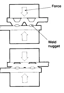
Fig. Projection welding
Application:
- Resistance welding is widely used in automotive industries.
- Projection welding is widely used in production of nut and bolt.
- Seam welding is used to produce leak prove joint required in small tanks, boilers etc.
- Fusion Welding and types
Joining of components by this mechanism is primarily based on fusion/melting of faying surfaces of the components to be joined using suitable heat source. Heat may also be used for melting filler metal or electrode depending upon the type of joining process. The heat required for melting can be produced using electric arc, plasma, laser and electron beam and combustion of fuel gases.
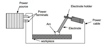
- Shielded metal arc welding: In this process, the heat is generated by an electric arc established between base metal and a consumable electrode. Electrode movement is controlled manually; hence, this process is also termed as manual metal arc welding. Shielded metal arc welding process can work on both AC and DC. Few fluxes (like cellulosic) provide large number of inactive gases for shielding of weld pool, while other fluxes form slag in ample amount to cover/protect the weld pool from the atmospheric gases.
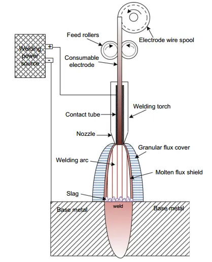
- Submerged arc welding: Submerged arc welding (SAW) process uses heat generated by an electric arc established between a bare consumable electrode wire and the workpiece. Since in this process, welding arc and the weld pool both are completely submerged under mound of granular fusible and molten flux therefore, it is called submerged arc welding. SAW is known to be a high current (sometimes even greater 1000 A) welding process and is mostly used for joining of heavy sections and thick plates as it offers deep penetration with high deposition rate and high welding speed. Submerged arc welding is used for welding of different grades of steels in many sectors such as shipbuilding, offshore, structural and pressure vessel industries for fabrication of pipes, penstocks, LPG cylinders and bridge girders.
- Gas tungsten arc welding: Tungsten inert gas welding process uses (a) an electrode primarily made of tungsten and (b) inert gas for shielding the weld pool. effective shielding is needed especially when welding highly reactive metals and alloys such as stainless steel, aluminum, and magnesium alloys, to develop high-quality weld joints for critical applications like nuclear reactors, aircraft. Moreover, welding of aluminum and its alloys with shielded metal arc welding process can be realized using halide flux-coated electrodes. The halide electrodes reduce problems associated with Al2O3 formation; however, halides fluxes are very corrosive. Therefore, welding of aluminum is preferably carried out using inert shielding environment with the help of Tungsten arc welding. This process is invariably recommended for joining of thin aluminum sheets of thickness less than 1 mm. Helium, Argon and their mixtures are commonly used as shielding gas for protecting the weld pool depending upon the metal to be welded, criticality of application and economics.
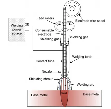
- Metal arc welding: The principle for Metal arc welding process for fusion welding is based on the melting of the faying surfaces of the base metal using heat produced by a welding arc established between base metal and a consumable electrode. Welding arc and weld pool are well protected by a jet of shielding inert/inactive gas coming out of the nozzle. A jet of shielding gas forms a firm shroud around the arc and weld pool to protect the weld pool. However, GMA weld is not considered as clean as that of gas tungsten arc weld. This process involves consumable electrode for establishing welding, and shielding jet is used to protect the welding pool from atmospheric gases. The shielding in GMAW can be achieved either using inactive gases like carbon dioxide, mixture of carbon dioxide and argon, argon and oxygen, argon and hydrogen or inert gases like helium and argon only.
- 3-2-1 Principle:
To ensure precision in any machining operation, the work must be properly positioned with respect to the cutter or other tool. This is called referencing. Repeatability is the feature of the tool that allows different parts to be machined consistently within their required tolerances. Accurate location is an important element in the repeatability of any tool.
3-2-1 Principle
- To accurately locate a part in a fixture, movements must be restricted. This is done with locators and clamps.
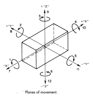
- By placing the part on a three-pin base, five directions of movement (2, 5, 1, 4, and 12) are restricted. Using pin- or button-type locators minimizes the chance of error by limiting the area of contact and raising the part above the chips.
- To restrict the movement of the part around the Z-Z axis and in direction eight, two more pin-type locators are positioned. To restrict direction seven, a single-pin locator is used. The remaining directions, nine, ten, and eleven, are restricted by a clamping device. This three-two-one, or six points, locating method is the most common external locator for square or rectangular parts.
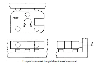
- Locators positioned under a part are referred to as supports. Locators position a part by its edges.
- The three primary supports are solid, adjustable, and equalizing. The major types of locators used to locate parts on an internal diameter are shank-mounted locators and pin locators. Pin locators may also be used to locate a part from its external edges.
6. Body Coordinate System
- A vehicle that is equipped with a body having a coordinate B(Cxyz) at its core.
- The centre of mass, denoted as C, is in the general domain. To establish a coordinate system, the x-axis runs longitudinally through C in a forward direction. The y-axis extends laterally to the left from the driver's perspective. The z-axis completes the coordinate system, forming a right-hand triad.
- The vehicle is positioned on a level, straight surface, with the z-axis forming a perpendicular angle.
- The surface, in contrast to the force of gravity's acceleration, denoted as "g." The mathematical formulas that govern this phenomenon.
- The movement of the vehicle is represented as B(Cxyz).
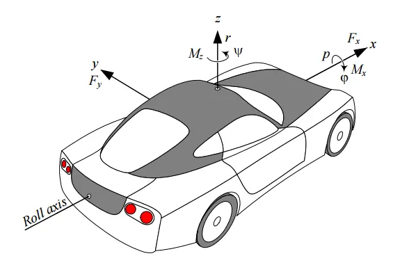
- Angular orientation and angular velocity: of a vehicle are expressed by three angles: roll ϕ, pitch θ, yaw ψ, and their rates: roll rate p, pitch rate q, yaw rate r.
- Vehicle force system (F,M) is the resultant of external forces and moments that the vehicle receives from the ground and environment.
- Roll model vehicle dynamics can be expressed by four kinematic variables: the forward motion x, the lateral motion y, the roll angle ϕ, and the yaw angle ψ. In this model, we do not consider vertical movement z, and pitch motion θ.
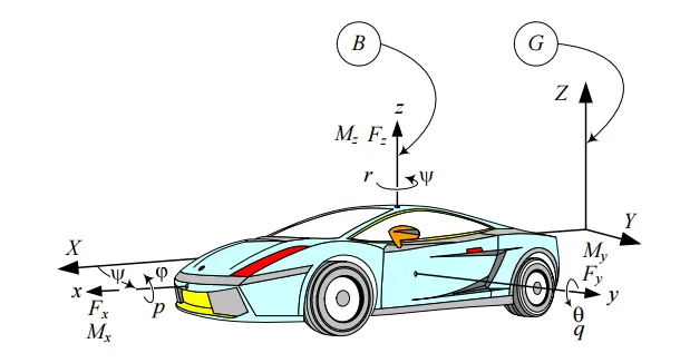
Fig. Body Coordinate frame
7. Body Plane System
Three mutually perpendicular imaginary planes make up the body plane. These are the automobile industry's reference for cars. The GD & T of every component in the automotive domain are defined using these. Body plane dimensions are the measurements from a body plane to a section.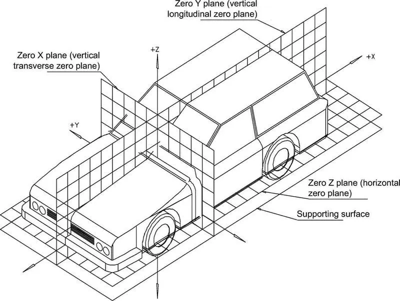
Bodyline dimension is crucial for the following reason.
- It specifies the precise location of each item in the vehicle with respect to a given origin.
- It guarantees an ideal structure for assembly.
- All design work is done in relation to bodylines while drawing lines, including fixture, turntables, etc.
- It makes it simple to find various elements of the car.
- It seeks to establish a uniform system.
- It aids in quality assurance.
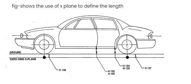
Fig. Example of measurement using body planes