Week 2:- BiW Fixture Basics Challenge
- What is the process of project execution activity?
Ans-
Project execution Activities are general activities need to perform in order to build a BIW fixture and tooling as per customers requirement.
The customer requirements are thoroughly represented in a basic RFQ i.e. request for quotation.
Here all requirements form customer are stated with details.
On the basis of RFQ, a study is done where technical and commercial offers. Time duration and flow of fixture is decided.
The offer is submitted to customer, for their requirements for flow and time duration are consideration.
Documents regarding details, material required, welding process standard parts etc. time involved in design, manufacturing, simulation and assembly, installation and commissioning are all described in detail.
A rough ideas about positioning of robots, fixtures etc, are mentioned.
Schedule Preparation-
On the base, technical and commercial offers are provided to customer.
Customer will provide PO if interested.
All detailed activities are planned once the PO is received by customer, taking into account all activities involved. All the activities are depending on previous activity.
Once Po received, project execution started as per schedule.
Final delivery date.
BOM Preparation-
Requirement of material for the fixture in terms of consumable, standard parts is created.
Part list
Design Concept Preparation-
On studying, requirement from customer, in LOI or PO, 3 D, 2 D drawings, Tolerance, manufacturing requirements material requirement, a concept design is prepared.
Customer Approval Process-
Once we provide conceptual design ti customer, by studying requirement by them, it is send for final approval.
If any additional features or modifications are suggested by their side, they can be added on account of additional charges depending on particular cost.
And once we get customers approval, next step is
Detailing and Drawing Release-
All parts detailed drawings are released for manufacturing.
Manufacturing-
Manufacturing is started for required parts.
Same time quality checking is also performed.
POP – for standard part is released too.
Mechanical/ Electrical Assembly-
Once Manufacturing of all parts is done, and quality is also checked, assembly of mechanical and electrical parts is done.
Quality Inspection-
At this level, quality inspection is performed to check.
Assembly is as per final drawing, co-ordinates, Relative Dimensions, resting are checked using CMM inspection is done.
Internal Trial- here put assy in fixture to check positions, proper clamping.
Trial is taken for Welding feasibility, connectivity of fixture is checked.
Pin position, clamping etc checked
Online Trial-
Automated trial performed on fully automated mode, where all connections, processes of various components are operated and tested.
Packing and Dispatch-
After successful trial of fixture, it is properly packed and dispatched.
Installation as per layout-
At customer end, installation is done as per layout which is designed at initial level.
Trial and training at customer end-
There will be production trials as per technical offer specifications.
Same training is provided to concerned people at customer side.
Buy off meeting-
Once it is done, buy off meeting is done.
Final Handover- After all the theses steps, final handover is taking plane.
- What are the types of joining processes?
Various joining processes are-
Resisting Welding – It’s a welding process used for joining sheet metals.
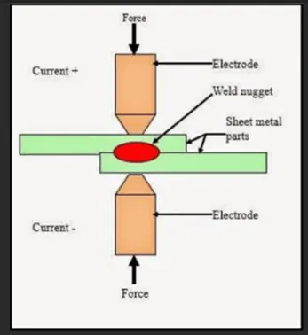
Sheet metal plates are hold together,
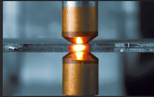
Electrodes are forced to hold the plates, once contact is done; current is passed between the electrodes.
Intensity of current is too high, and plates are thin.
Resistance offered by the plates creating heat at the nearby area. This results in melting of sheet metal plates under electrode. The melt get solidified and joins plates locally.
Heating Media- Current, Heat due to resistance to current offered by the metal sheets.
Advantages-
- No any mark on outer surfaces of metal sheets. Hence most widely udes in automobiles.
- Fast process.
- Due to localized process, weakening of nearby area not affecting much.
There three types of resistance welding-
- Spot Welding. A single spot is is result of welding.
- Seam Welding-
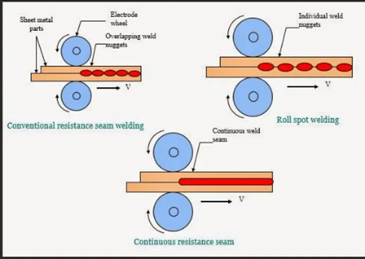
Series of overlapping spots, to obtain a leak proof joint. Here electrodes are in the form of cylinders.
- Projection Welding-
When joint of dissimilar shapes to a flat surface is requires, projection welding is used. It welds an area at a time rather that a spot.
Sheet metal plates are hold together,
Electrodes are forced to hold the plates, once contact is done; current is passed between the electrodes.
Intensity of current is too high, and plates are thin.
Resistance offered by the plates creating heat at the nearby area. This results in melting of sheet metal plates under electrode. The melt get solidified and joins plates locally.
Fusion Welding
Arc Welding-
It is a joining process of similar dissimilar metals with the help of fusion of electrode using electric current DC or AC. The electrode may be consumable or non-consumable. Also shielded gases may or may not be used.
Arc temperature is too high to melt the parent metal to melt and filler rod get diffused with liquid molten metal and solidifies.
Various Arc Welding processes-
Manual Metal Arc Welding Process (MMAW)-
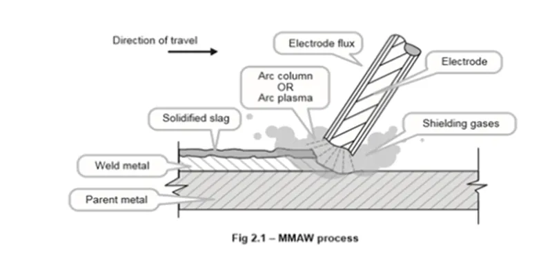
MMAW is a welding process that creates an electric arc between an electrode which is hand held, flux-coated and consumable. It is acting as a filler too.
The arc heat melts the parent metal and electrode.
As the flux coating breaks down in the arc it produces a gaseous shield that excludes atmospheric gases from the weld zone.
The flux coating also prevents an oxidizing action and forms a slag on the cooling weld. It results in stronger joint.
Requirements-
a suitable and constant current power source (AC or DC),
flux-covered consumable electrodes.
Limitations- Being manual operation, process Is not suitable for Mass production.
Gas shielded Metal Arc Welding- (GMAW)
In this process, arc is stuck between meatal to join and a consumable or non-consumable electrode, with a shielding gas, which is an Inert Gas.
MIG Welding (Metal Inert Gas Welding MIG welding)-
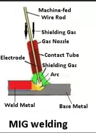
The arc is struck between the workpiece and a metal wire electrode which is continually fed forward into the arc.
Electrode is in the form of wire or thin filament bundle.
Inert gases are either argon or a mixture of argon-helium, and CO2 as well, applied through a nozzle.
A DC Constant Voltage Machine performs MIG welding.
Generally, the MIG welding process is quicker than traditional processes.
TIG Welding (Tungsten Inert Gas Welding MIG welding)-
It is a highly versatile process that can be used on thin sheets of metal.
It is also works with alloys such as stainless steel and aluminum.
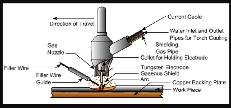
In a TIG welding process, a high intense arc is produced between tungsten electrodes
(Non-consumable) and work piece. Filler rod is held in position to obtain desired welded joint. This arc produces heat energy which is further used to join metal plate.
A shielding gas is also used which protect the weld surface from oxidization.
Both AC and DC power sources can be used.
Advantages.-
- TIG welding can be used for joining dissimilar metals.
- Wide range of applications- stainless steel, carbon base alloy, copper base alloy, nickel base alloy etc. can be joined by TIG welding.
- Al and its alloys can also be welded using TIG welding.
Submerged Arc Welding Process-
It is arc welding process in which a shielding gas is not required.
The arc is submerged beneath the flux blanket and is not visible normally.
It is a well-established and extremely versatile method of welding.
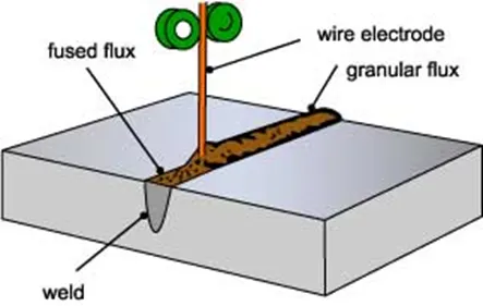
The electrode may be a solid or cored wire or a strip.
The flux may be made by either fusing constituents or by agglomerating the constituents using a binder and a corning process.
The chemical nature and size distribution of the flux assists arc stability and also determines the mechanical properties of the weld metal and the shape of the bead.
Process-
Depth , penetration of weld, position of feeler wire, chemical composition of deposited metal arc voltage, travel speed of electrode are main parameters which decides weld quality, as it is not visible.
This welding technique is ideally suited to the longitudinal and circumferential butt welds required for the manufacture of line pipe and pressure vessels.
Mechanical Fasteners-
They are used in following cases-
Especially Al parts are joined using fasteners as its weldability is poor.
For such metals who’s weldability is poor e.g. Al.
They are screw and bolted joints.
Self Piercing Rivetted Joints-
Speciilay for steel and aluminum, fast joining process foe sheets.
It is a single step technique.
Self-piercing Rivets are semi tubular, and some are solid rivets.
No need of previous drilled holes.
Hemming-
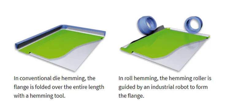
Joining of outer and inner panels of an automobile is obtained by hemming process.
A sealant is placed between two panels to resist foreign particles to enter in the panels and to foolproof the joint.
The edges of outer panels are pressed along inner panels with rollers. ‘A relief corner is maintained at curvatures.
Adhesive Bonding-
It’s a joining process to join two surfaces with the smooth joint using epoxy, glues and some plastic agents.
Q3. What are Resistance Welding & its application in the automotive sector?
Resisting Welding – It’s a welding process used for joining sheet metals.
Sheet metal plates are hold together,
Electrodes are forced to hold the plates, once contact is done; current is passed between the electrodes.
Intensity of current is too high, and plates are thin.
Resistance offered by the plates creating heat at the nearby area. This results in melting of sheet metal plates under electrode. The melt get solidified and joins plates locally.
Heating Media- Current, Heat due to resistance to current offered by the metal sheets.
Advantages-
- No any mark on outer surfaces of metal sheets. Hence most widely udes in automobiles.
- Fast process.
- Due to localized process, weakening of nearby area not affecting much.
There three types of resistance welding-
- Spot Welding. A single spot is result of welding.
Electrodes are forced to hold the plates, once contact is done; current is passed between the electrodes.
Intensity of current is too high, and plates are thin.
Resistance offered by the plates creating heat at the nearby area. This results in melting of sheet metal plates under electrode. The melt get solidified and joins plates locally.
- Seam Welding-
-
Series of overlapping spots, to obtain a leak proof joint. Here electrodes are in the form of cylinders.
In seam welding, a continuous weld is created along the weld joint.
This can be performed for both flat and corner welds.
Since they cover the entire length of the weld joint, seam welding is performed whenever pipes and tubes must be joined.
These welds are more durable and stronger than stitch or spot welds
3. Projection Welding-
When joint of dissimilar shapes to a flat surface is requires, projection welding is used. It welds an area at a time rather that a spot.
Sheet metal plates are hold together,
Electrodes are forced to hold the plates, once contact is done; current is passed between the electrodes.
Intensity of current is too high, and plates are thin.
Resistance offered by the plates creating heat at the nearby area. This results in melting of sheet metal plates under electrode. The melt get solidified and joins plates locally
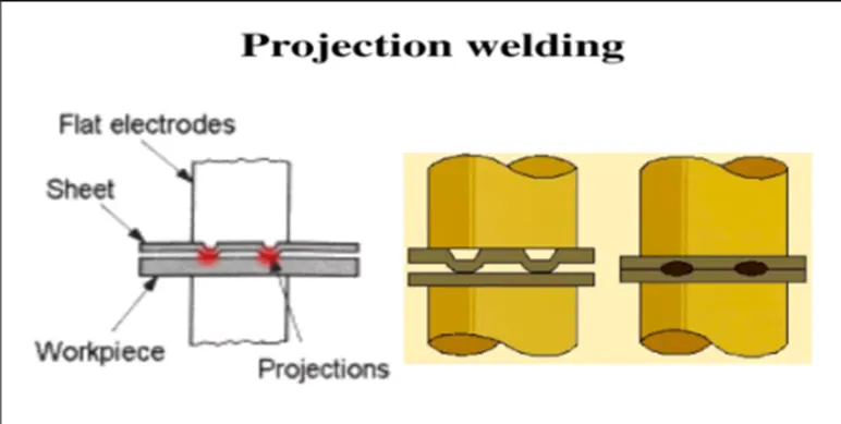
Applications of Resistance welding in automotive industries-
- This type of welding can be widely used within automotive industries; about 5000 spots are there in an automobile.
- Being a quick process and no any weld mark on outer surface, this welding is most common in automobile.
- Underbody, roof, door, side wall and body assembly.
- Resistance seam welding is used in automobile fuel tanks.
- Seam welding and projection welding are used in the manufacture of automobile shock absorbers, and in the production of automobile rims.
- What is fusion welding & types of fusion welding with its application in the automotive sector?
Fusion Welding-
It is a joining process of similar or dissimilar metals with the help of fusion of electrode using electric current DC or AC. The electrode may be consumable or non-consumable. Also shielded gases may or may not be used.
Arc temperature is too high to melt the parent metal to melt and filler rod get diffused with liquid molten metal and solidifies.
Various Arc Welding processes-
Manual Metal Arc Welding Process (MMAW)-
MMAW is a welding process that creates an electric arc between an electrode which is hand held, flux-coated and consumable. It is acting as filler too.
The arc heat melts the parent metal and electrode.
As the flux coating breaks down in the arc it produces a gaseous shield that excludes atmospheric gases from the weld zone.
The flux coating also prevents an oxidizing action and forms a slag on the cooling weld. It results in stronger joint.
Requirements-
a suitable and constant current power source (AC or DC),
flux-covered consumable electrodes.
Limitations- Being manual operation, process Is not suitable for Mass production.
Gas shielded Metal Arc Welding- (GMAW)
In this process, arc is stuck between meatal to join and a consumable or non-consumable electrode, with a shielding gas, which is an Inert Gas.
MIG Welding (Metal Inert Gas Welding MIG welding)-
The arc is struck between the workpiece and a metal wire electrode which is continually fed forward into the arc.
Electrode is in the form of wire or thin filament bundle.
Inert gases are either argon or a mixture of argon-helium, and CO2 as well, applied through a nozzle.
A DC Constant Voltage Machine performs MIG welding.
Generally, the MIG welding process is quicker than traditional processes.
TIG Welding (Tungsten Inert Gas Welding MIG welding)-
It is a highly versatile process that can be used on thin sheets of metal.
It is also works with alloys such as stainless steel and aluminum.
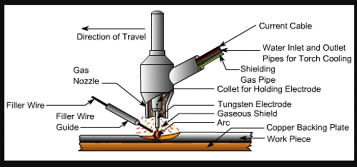
In a TIG welding process, a high intense arc is produced between tungsten electrodes
(Non-consumable) and work piece. Filler rod is held in position to obtain desired welded joint. This arc produces heat energy which is further used to join metal plate.
A shielding gas is also used which protect the weld surface from oxidization.
Both AC and DC power sources can be used.
Advantages.-
- TIG welding can be used for joining dissimilar metals.
- Wide range of applications- stainless steel, carbon base alloy, copper base alloy, nickel base alloy etc. can be joined by TIG welding.
- Al and its alloys can also be welded using TIG welding.
Submerged Arc Welding Process-
It is arc welding process in which a shielding gas is not required.
The arc is submerged beneath the flux blanket and is not visible normally.
It is a well-established and extremely versatile method of welding.
The electrode may be a solid or cored wire or a strip.
The flux may be made by either fusing constituents or by agglomerating the constituents using a binder and a corning process.
The chemical nature and size distribution of the flux assists arc stability and also determines the mechanical properties of the weld metal and the shape of the bead.
Process-
Depth , penetration of weld, position of feeler wire, chemical composition of deposited metal arc voltage, travel speed of electrode are main parameters which decides weld quality, as it is not visible.
This welding technique is ideally suited to the longitudinal and circumferential butt welds required for the manufacture of line pipe and pressure vessels.
Fusion Arc Welding in automobile -
TIG welding is makes a rust-resistant metal fusion.
This ability is widely applied in the automobile industry to avoid rusting of crucial vehicle parts. Additionally, it strengthens the bond makes it tough.
MIG welding is in the automotive industry is very common.
MIG welding is employed for automotive repairs. no matter what the size of the vehicle is,
it provides sturdy and robust welds up to a mark of 0.5mm makes it more top choice.
- What is the 3-2-1 principle?
For any fixture, location of parts is most important.
A fixture should lock all degrees of freedom of the part to be processed, while operation is performed.
There are 12 degrees of freedom- 6 rotational and 6 translational.
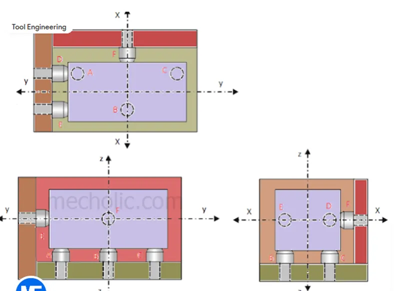
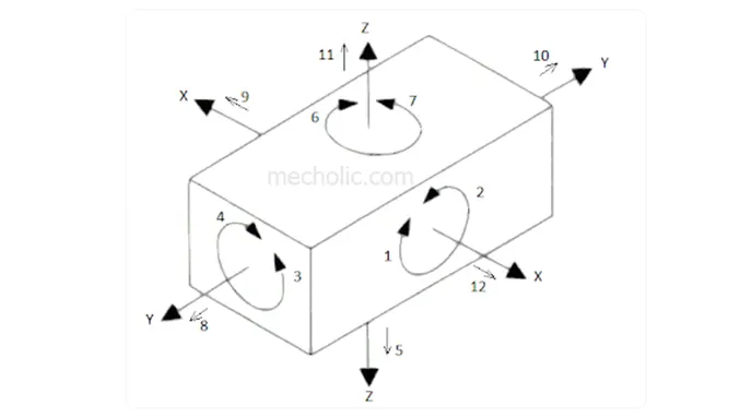
3-2-1 is a principle of location (six point location principle) is used to constrain the movement of workpiece along the three axes XX, YY, and ZZ on a fixture.
This is achieved by providing six locating points.
3 pins in base plate, 2 pins in vertical plane and 1 pin in a plane which is perpendicular to first two planes.
Pins A, B, C on the base plane (Primary Plane) restrict the rotation of component about X axis and Y axis.
It also limits the downward movement of component along Z axis. Ie. 1,2,3,4 and 5 degrees of freedom are restricted.
Pins D, E is in plane parallel to the plane containing X and Z axes. It prevents the rotation of component about Z axis (6, 7 degree of freedom) and the movement of the body in along Y axis towards one direction (8 degree of freedom).
The last pin F is in a plane parallel to plane contains Y and Z axes. It restricts the movement component along X axis in one direction.
Three remaining degree of freedom 10, 11, 12 are kept as it is. This will facilitate loading of part in fixture and then it can be restricted.
Basic rules for locating components are-
- Fewer number of locator.
- Locators spaced as much as apart possible and make sure complete contact of locating device.
- Degree of freedom of locating device must be reduced to zero.
- Locator must be foolproof. Any wrong positon loading of part should not possible.
The component can only be loaded into the fixture in the correct position.
- Locator should provide sufficient gap to accumulate burr during operation.
Locating Surfaces-
Primary surface should be max flat, and larges surface.
Secondary surface should be second largest and perpendicular to primary surface.
Third surface should be perpendicular to first and second surface.
Q 5. Define Body coordinate system?
Body planes or body co-ordinate system in BIW-
Body Co-ordinate system (BCS) is an origin of the car, is a reference system which consists set of points, line and surfaces used to define position of points in space. It can be any part in a car.
For drawing body parts, dimensions, product and process design, this BCS is origin.
BCS is also called body line or car line.
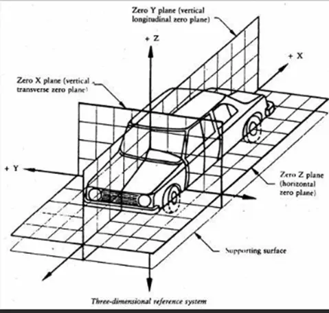
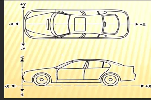
X- Longitudinal Direction (For and After or Front –O – Line FOL), indicate length of car
Y- Transverse Direction (Cross Car or Centre –O- Line) indicate width of car
Z- Vertical Direction (Up 0Down or Bottom –O –Line) indicate height of car
Car maker to car maker, BCS can be different.
Q6 Elaborate Body plane system & its importance.
Body planes are reference planes to a car and are used to GDNT for all parts.
These body planes are mutually perpendicular imaginary planes.
They are located at either driver’s position or in engine location or at front end of the car.
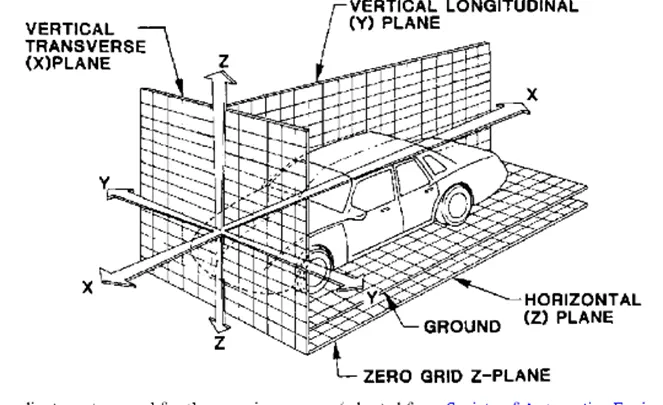
Body Lines or Body planes are called –
Front –O – Line FOL, measurement along FOL or X direction is called Front Aft or F/A
Centre –O- Line COL, measurement along COL or Y direction or - Transverse Direction is known as Cross Car.
Bottom –O –Line, measurement along BOL or Z direction or - Vertical Direction (U/D, or UP/ Down)
Importance of Body Planes-
It defines position of each part in a car with respect to a fixed origin i.e. BCS
While designing other components like fixture, turn table etc, all designs are carried out relative to body line.
It assists for easy location.
Aims to create a standardized system.
Assist in quality check.