Week 2:- BiW Fixture Basics Challenge
Q1. What is the process of project execution activity?
Project activities are the tasks from the start to end of the project. There are various steps involved in the projects. The various steps are described below.
- RFQ received:
This id the first step in any project. RFQ stands for Request for Quotation. In this customer specifies his requirements,specifications etc. in form of documents or data. Also customer specifies its Technical offer, commercial offer, how the project will be executed & timeline to complete the project in it.
- 1st spec discussion & offer submission:
In this the documents re;ated technical offer, commercial offer, project execution, Timeline required to complete the project are prepared. The time required to 3D design,Analysis of design, drawing & detailing, manufacturing, Assembly & commisioning etc. is considered. Then the cost of all the operation is also considered. By considering these kind of things the offer is prepared & submitted to the customer.
- LOI/PO Receipt:
The customer will study the offer submitted. He will also take quotations from others. The customer will study all the offers, compare offers & then select oner offer which suits best. The customer will generate po means Purchase order to start the work.
- Schedule preparation:
After receiving the PO the project officially start. The timeline is fixed so there should be plan to beat the deadline & to complete the project. All the activities step by step are taken into account like po receipt, 1st meeting, design date analysis, 3D design preparation & simulation etc. the time required to finish the individual activity is calculated. By calculating all the steps the total time required is calculated. It should beat the timeline & if not then modifications is done in schedule to beat the timeline of the project. We should have some back up plan for this Because due to some reasons our tasks not complete on the fixed date or the next task is dependant on previous task.
- BOM preparation
Bill of material is prepared for the project like the BO parts, grippers, cylinders, motors etc. which are required.
- Design concept preparation -
The customer gives data or the specifications for the design. Based on that data design process is start which fulfills all the customer requirements.
- Customer approval -
After designing the concept the approval of the customer is required. Customer checks the design fulfills the requirements or not according to the technical offer. If yes the customer gives approval for the design or customer will also ask for some addition or the changes in the design. By doing the necessary changes final approval is taken from the customer.
- Detailing & DWG release -
After the approval from customer DWG are released whic shows the detailed specifications of all the parts required. Like dimensions, Qty, Specifications etc.
- Manufacturing BOP ordering -
The BO parts like motors, cylinders, sensors, gripper etc. required for manufacturing are ordered as per the design specifications.
- Mechanical/ Electrical assembly-
Once the parts are received they goes for the prior Quality control checking. In this all the parts are checked as per the specification. After QC checking the Mechanical or electrical assemblis are prepared as per the design.
- Quality inspection -
After the assembly again the quality is checked. In this all the dimensions, positional accuracy, Coordinates are checked by using CMM machine.
- Internal trial & testing & online trial -
After the QC check internal trials are taken to check the fixture can do the operation or not for what it is designed. The simulation is done for this purpose at early stage. In this the fixture is checked for the clamping of the part, welding ,proper loading & unloading of the part etc.
After this online trial is taken in which all the operations done in automated mode by using electrical connections. The process sequence is checked as per the defined way in design in automated mode. Customer is also involved in online trial for taking the approval.
- Packaging & dispatch -
The assemblies are packed in proper manner. Because in trasportaion the fixture will be damaged hence it distorts the geometry of the fixture & also the functionality of the fixture. Hence the proper packaging is very important. Once the packaging is done the fixture is dispatched to the customer address.
- Installation as per layout -
Layout is the space defined for the parts like fixture, robots etc, according to the functionality,application, process sequence etc. The layout is done at very initial level & according to that installation is done.
- Trials & training at customer -
Production trials are taken at customers end. In tecnical offer we have specified the quality benchmarks for the fixture, the capability of the fixture for production etc. The trials are taken to check the capability of the fixture. Once it is done then training is given to the operator, staff & engineer for the process sequence, how the fixture works, loading & unloading of the part etc.
- Buy off meeting & Final handover -
After production trial & training Customer check all the prescribed things in the offer are done or not. Sometime customer want some addition work also, so according to the rquirement all the points are closed & after that project finally handovered to the customer.
Q2. What are the types of joining processes?
There are various joining process used in BiW design catogorised in 2 types:
- Metallurgical Joining Process
- Mechanical Joining Process
- Metallurgical Joinig process
Metallurgical joining includes fusion welding, pressure welding and brazing/soldering which use different energies. There are also methods of chemical joining that use adhesives.
Every joining method has advantages and disadvantages. To ensure efficient joining, you need to select the right method according to the materials and joining conditions.
1. Welding:
Welding is a fabrication process whereby two or more parts are fused together by means of heat, pressure or both forming a join as the parts cool.
The heat applied should be such that the work piece should melt, i.e., the temperature at which welding is done, should be more than the melting point of the work piece to be welded. Welding is distinct from lower temperature metal-joining techniques such as brazing and soldering, which do not melt the base metal.
In addition to melting the base metal, a filler material is typically added to the joint to form a pool of molten material (the weld pool) that cools to form a joint that, based on weld configuration can be stronger than the base material (parent metal). Pressure may also be used in conjunction with heat or by itself to produce a weld Welding also requires a form of shield to protect the filler metals or melted metals from being contaminated or oxidized. Many different energy sources can be used for welding including a gas flame (chemical), on electric arc (electrical), a laser, an electron beam friction and ultrasound While often an industrial process, welding may be performed in many different environments, including in open air, underwater and in outer space Welding is a hazardous undertaking and precautions are required to avoid bums electric shock vision damage, inhalation of poisonous gases and fumes, and exposure to intense ultraviolet radiation
The above figure describes the different types of Welding process used in todays world.
2. Brazing:
Brazing is a metal-joining process in which two or more metal items are joined together by melting and flowing a filler metal into the joint, with the filler metal having a lower melting point than the adjoining metal.
Brazing differs from welding in that it does not involve melting the work pieces. Brazing differs from soldering through the use of a higher temperature and much more closely fitted parts than when soldering. During the brazing process, the filler metal flows into the gap between close-fitting parts by capillary action. The filler metal is brought slightly above its melting (liquidus) temperature while protected by a suitable atmosphere, usually a flux. It then flows over the base metal (in a process known as wetting) and is then cooled to join the work pieces together. A major advantage of brazing is the ability to join the same or different metals with considerable strength.
3. Soldering:
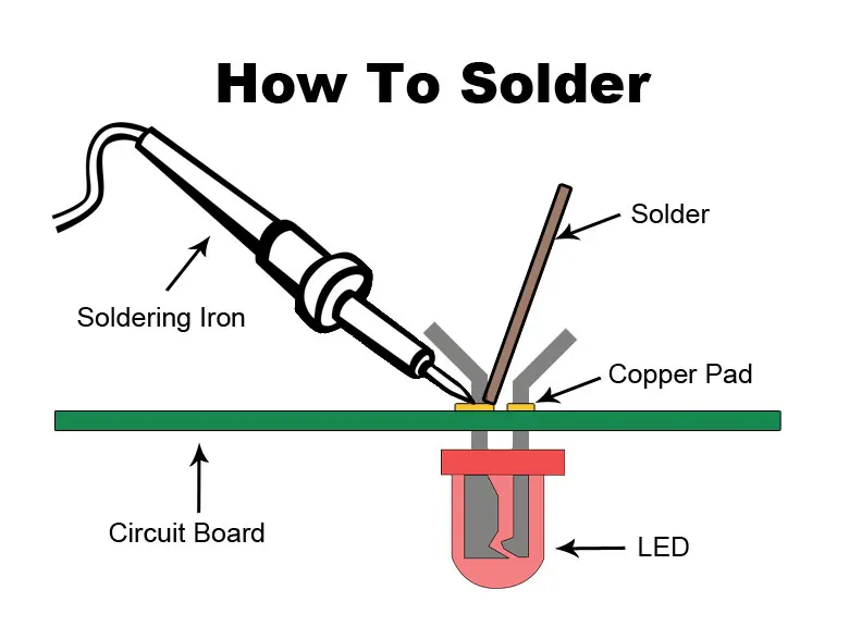
Soldering is a process in which two or more item are joined by melting and putting a filler metal (solder) into the joint, the filler metal having a lower melting point than the adjoining metal. Unlike welding, soldering does not involve melting the work pieces. In brazing, the work piece metal also does not melt, but the filler metal is one that melts at a higher temperature than in soldering. In the past, nearly all solders contained lead, but environmental and health concerns have increasingly dictated use of lead-free alloys for electronics and plumbing purposes.
4. Adhesive Bonding:
Adhesive Bonding is the process of joining two surfaces together, usually with the creation of a smooth bond. This may involve the use of glue, epoxy, or one of a wide range of plastic agents which bond either through the evaporation of a solvent or through curing via heat, time, or pressure.
High adhesive bond strength is achieved if chemical bonds are formed between the adhesive and the base material, or adherent. However, compared to welding, brazing, and soldering, it is not easy to achieve primary bonding (ionic, covalent, and metallic) in adhesive bonds because of the relatively larger interfacial gaps between the adhesive and the adherent. Secondary bonds, which do not involve electron transfer or electron sharing but instead rely on coulombic forces of attraction, is therefore more likely to form in adhesive bonding.
To maximize adhesive bonding strength, surfaces to be joined by adhesives must be cleaned thoroughly. This, in essence, minimizes the interfacial gap between the adhesive and the adherent. Making the surfaces 'rough' also improves adhesive bond strength because of the mechanical interlocking that the 'roughness' provides.
5. Diffusion Bonding:
Diffusion bonding is a technique which employs the solid state diffusion of atoms as a main process for the development of a joint. Diffusion bonding involves keeping the work pieces to be joined in close contact under moderate pressure and heating the assembly at an elevated temperature for a certain duration.
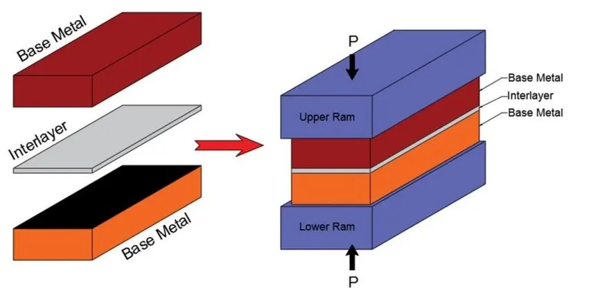
When joining two materials of similar crystalline structure, diffusion bonding is performed by clamping the two pieces to be welded with their surfaces abutting each other. Prior to welding, these surfaces must be machined to as smooth a finish as economically viable, and kept as free from chemical contaminants or other detritus as possible. Any intervening material between the two metallic surfaces may prevent adequate diffusion of material. Specific tooling is made for each welding application to mate the welder to the workpieces.[10] Once clamped, pressure and heat are applied to the components, usually for many hours. The surfaces are heated either in a furnace, or via electrical resistance. Pressure can be applied using a hydraulic press at temperature; this method allows for exact measurements of load on the parts. In cases where the parts must have no temperature gradient, differential thermal expansion can be used to apply load.
- Mechanical Joining Process:
Mechanical joining is a process for joining parts through clamping or fastening using screws, bolts of rivets Advantages of mechanical joining include versatility, ease of use, and the option to dismantle the product in cases where regular maintenance requires it The ability to join dissimilar materials is another benefit. A drawback of using mechanical joining is the lack of a continuous connection between parts, because the joint is achieved through discrete points. Also, holes created for joining are vulnerable to fractures and corrosion
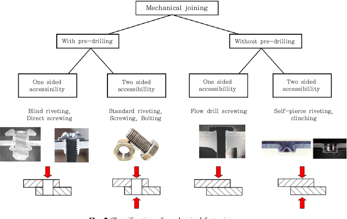
Mechanical joining-also called joining by forming - has become interesting for the automotive industry due to the request to reduce fuel consumption and thereby emissions order to reduce weight on the car body, the usage of lightweight materials in the body white application has increased. This includes aluminium, high-strength steel alloys, prymers and composites. Here the different type of mechanical joining becomes important. All mechanical joining methods are cold forming techniques. One general Benes for all mechanical joining methods is the mobility of the material after joining At the same time mechanical joining offers an impressive strength.
Q3. What is Resistance Welding & its application in the automotive sector?
Resistance welding, sometimes called electric resistance welding (ERW),is a process by which metals can be joined together by applying pressure and conducting a strong electric current through the metal combination to heat up the welding joint and melt the metals, forging them together.
Resistance welding is generally used to join two plain metal work pieces together. An electric current is delivered to the metal sheets (or any work pieces being joined) through weld electrodes which apply force to the sheets. This force is then converted to heat. The heat is generated so that it melts the metal at the point where they join – the point of ‘resistance’ between the faying surfaces. The electrode then extracts heat from the molten weld area which forms a weld nugget at the point where it solidifies. A force is applied before, during and after a current is applied, which confines the contact area.
1. Resistance Spot Welding
Resistance spot welding has been used extensively in the automotive industry for the joining of steel and in the aerospace industry for airframe components made from aluminium alloys. It is one of the oldest and simplest forms of resistance welding, in which a weld nugget is produced by passing an electric current between the two metal components whilst they are held together between electrodes, typically made from copper-based alloys due to its superior conductive properties.
2. Resistance Seam Welding
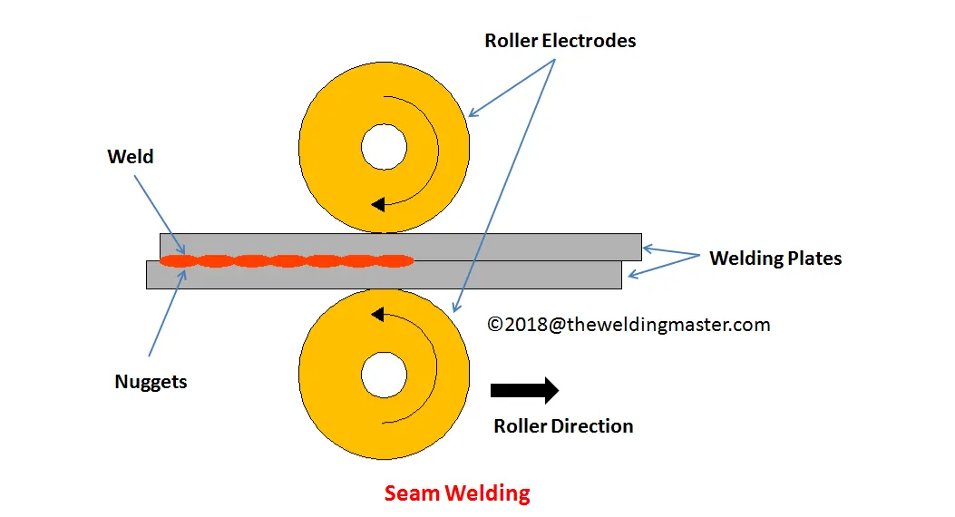
Resistance seam welding is a variation of the standard spot welding form, however instead of spot one nugget, a series of overlapping nuggets is produced. This is usually done by replacing the conventional spot welding electrodes with wheels, which turn as the parts are fed between them. The process thus produces a continuous welded seam rather than a single spot. Seam welding is often used in the production of thin sheet, leak-tight containers such as fuel tanks, and is generally unsuitable for welding aluminium.
3. Resistance Projection Welding
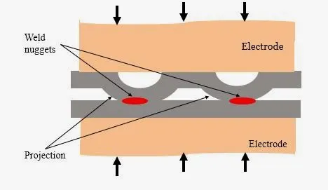
Resistance projection welding is a form of resistance welding where the electricity, force, and weld time are concentrated on raised ‘projections’ across the surface. Projection welding is generally used for welds using thicker materials than the thinner metal pieces that spot welding is usually required for, and often not metals. It is used primarily in the electrical, automotive and construction industries.
4. Resistance Butt Welding
Resistance butt welding is a process in which the two components of similar cross section can be joined together in one operation that takes place simultaneously across the entirety of the affected object, rather than just in small spots. The welding application of butt welding is often in wires and rods with small diameter measurements, generally up to about 16mm diameter.
5. Flash Butt Welding
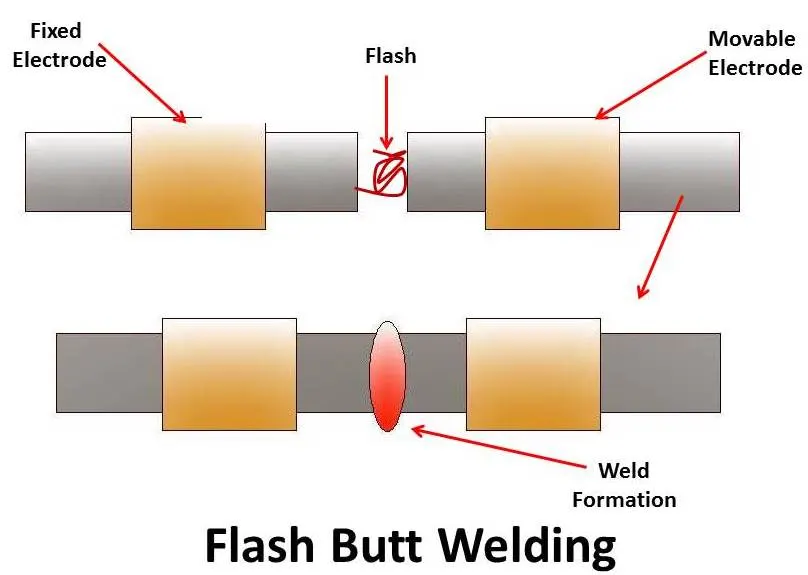
Flash butt welding is similar, but in this case the energy transfer is primarily provided by the resistance heat arising from the parts themselves. This is a faster type of resistance welding where the welder joins the parts by applying some pressure, then by passing a heavy current through the joint which burns away surface irregularities. After the weld has generated enough heat, the parts are connected by applying heat and pressure simultaneously. This produces a forge butt weld with no melted metal remaining in the joint.
Resistance welding machines are designed and built for a wide range of automotive, aerospace and industrial applications. Through automation, the action of these machines is highly controlled and repeatable allowing manufacturers to staff production readily.
RW technology is employed in manifold industries, such as:
- Transportation industries
- Automotive construction (body parts, frames, add-on parts such as doors & tailgates etc.)
- Commercial vehicles
- Rail vehicles
- Sheet metal forming industries
Q4. What is fusion welding & types of fusion welding with its application in the automotive sector?
Fusion welding processes can be grouped according to the source of the heat, for example, electric arc, gas, electrical resistance and high energy.
These processes include:
Arc Welding Processes - with the most common processes being:
- Shielded Metal Arc Welding (SMAW), also known as manual metal arc welding (MMA or MMAW), flux shielded arc welding or stick welding. Suitable for welding ferrous and non-ferrous materials in all positions.
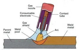
- Metal Inert Gas Welding (MIG) and Metal Active Gas Welding (MAG), also known as Gas Metal Arc Welding (GMAW). MIG and MAG welding are the most common arc welding processes, in which an electric arc forms between a consumable wire electrode and the workpiece leading them to melt and join. Both use a shielding gas to protect the weld from airborne contaminants, or oxidation in the case of MIG welding.
- Tungsten Inert Gas Welding (TIG), also known as Gas Tungsten Arc Welding (GTAW). This arc process uses a non-consumable tungsten electrode to create the arc between the electrode and the base plate. An inert shielding gas is used to protect from oxidation or other atmospheric contamination. This process can be used autogenously on thin parts, but will require the addition of a wire, rod, or consumable to be added for thicker parts.
- Plasma Arc Welding (PAW). This process uses an electric arc created between an electrode and the torch nozzle. The electric arc ionises the gas (usually argon) in the chamber creating what is called a 'plasma.' It is then forced through a fine bore copper nozzle that constricts the arc and directs it to the workpiece, allowing the plasma arc to be separated from the shielding gas (which is usually made from a mixture of argon and hydrogen).
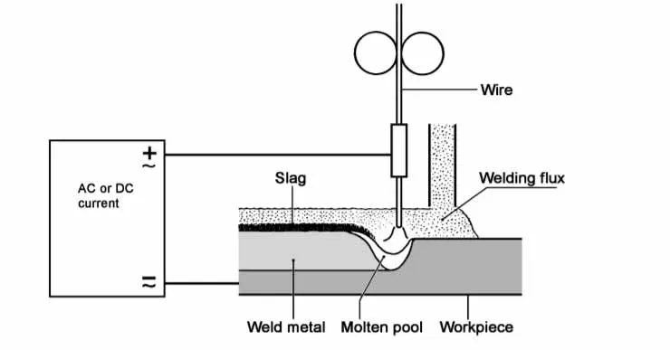
- Submerged Arc Welding (SAW). This frequently-used arc welding process uses a continuously-fed consumable electrode and a blanket of fusible flux which becomes conductive when molten and provides a current path between the workpiece and the electrode. The flux also prevents spatter and sparks while suppressing ultraviolet radiation and fumes.
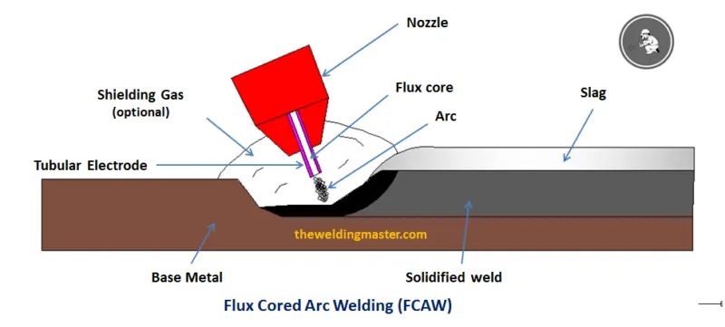
- Flux Cored Arc Welding (FCAW). Developed as an alternative to SMAW, this process uses a continuously fed consumable electrode with a flux and a constant voltage or constant current power supply. Sometimes using a shielding gas this process can also just use the flux to provide protection from the atmosphere.
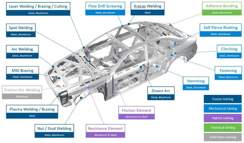
The above image shows the different welding process used in different parts of the Automotive BIW.
Q5. What is the 3-2-1 principle?
In BIW fixture design Fixture works on 3-2-1 principle.
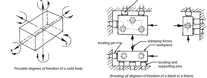
The 3-2-1 principle states that the six locators are sufficient to restrict the required degree of freedom of any workpiece. In this, motion is restricted using clamps and locators. A three-pin base can restrict five motions and six pins restrict nine motions.
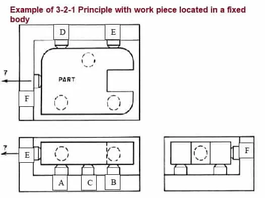
[1] The workpiece is resting on three pins A, B, and C which are inserted in the base of the fixed body.
[2] The workpiece cannot rotate about the axes XX and YY and also cannot move downward.
[3] In this way, the five degrees of freedom 1,2,3,4 and 5 have been arrested.
[4] Two pins D and E are inserted in the fixed body, in a plane perpendicular to the plane containing pins A, B & C.
[5] Now the workpiece cannot rotate about the Z-axis and also it cannot move towards the left.
[6] Hence the addition of pins D and E restrict three more degrees of freedom, namely 6, 7, and 8.
[7] Another pin F in the second vertical face of the fixed body, arrests degree of freedom 9.
Each direction of movement is counted as one degree of freedom. i.e. a body in space has twelve degree of freedom.
The above method of locating a workpiece in a fixture is called the 3-2-1 Principle.
Q6. Define Body coordinate system?
A coordinate system is a reference system consisting of a set of points,lines and surfaces,used to define the positions of points in space in either two or three dimensions. In general BCS is also called as car line and body line.
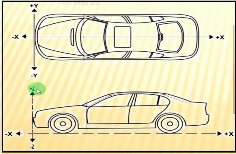
All vehicle product drawings are identified numerically relative to three vehicle
planes described and shown below.
- Transom line (TL), “X”, Length (L)
- Bow line (BL), “Y”, Width (W)
- Water line (WL), “Z”, Height (H)
X-Longitudinal direction (Fore/After or Front O line- FOL)
Y-Transverse direction (Cross car or Centre O line-COL)
Z-Vertical direction (Up & Down or Bottom O line - BOL)
The origin of the body coordinate system (OX) is defined at the front centre of a vehicle. It indicates a length of a car and the coordinate system (O2) is below the underbody indicates the height of the care and the coordinate system (OY) is the starting point is the centre of car body indicates width of the car.
Q7. Elaborate Body plane system & its essentials.
Body planes:
- Body planes are the reference planes in an automotive car. These planes are used to define the GD&T of all car parts in a automotive domain
- Body planes are generally considered to be present at the driver position or sometimes at the engine location or at the front end of the car, depending on the customer.
- The measurements from the body planes to the parts are called as bodyline dimensions
- These body planes are essential for the below reasons It defines the exact position of each product in the vehicle from the fixed origin
- It ensures flawless design for assembly while designing lines, all the designs are carried out relative to the bodyline.
- It assists in easy location of different parts in a vehicle,
- It aims in creating a standardized system
- It assists in Quality Checks