Grid Dependency Test on Bevel Gear
AIM:
- To perform Grid Dependency Test on a Bevel gear pair using different Mesh size and find the best results in ANSYS Workbench.
OBJECTIVES OF THE PROJECT:
- To define material for the spur gear pairs.
- To define contact faces for the teeth.
- To define revolute joint for the gears.
- To define the rotation and moment on the gears.
- To perform mesh on the gear pair.
- To define face sizing for fine meshing on the teeth faces.
- To evaluate the maximum stress, strain and deformation.
- To define the best results for a mesh size.
GRID DEPENDENCY:
- Grid dependency test ia a method used in FEA to get the optimum results by reducing mesh density in a given component.
- Mesh refinement, mesh convergence are the other names used to define Grid dependency test.
- The simulation softwares does not provide us the accurate mesh size for our model to get the optimum results, their work is to provide the results by conducting simulation based on the mesh size entered by us. Thus our job is to enter the correct mesh size to begin a simulation that results in optimum value. As a human we don't know the correct mesh size to get the optimum results. Hence we are undergoing grid dependency test.
- Here in grid dependency test we start the simulation with coarse mesh or a greater mesh element size and then we reduce the mesh element size step by step till we get the optimum result after which there won't be any changes in the optimum results even though we further refine the mesh.
PROCEDURE:
- Case 1
- OPEN > WORKBENCH > NEW PROJECT > STATIC STRUCTURAL.
- This will define static structural project.
- Now, go to ENGINEERING DATA > EDIT > STRUCTURAL STEEL.
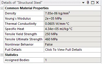
- Check whether structural steel is the default material added.
- Go to GEOMETRY > IMPORT > BROWSE > BEVEL_GEAR.STP.
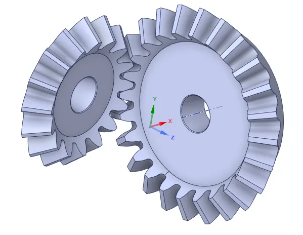
- This will import the bevel gear geometry.
- Now, open spaceclaim to edit the geometry.
- In the spaceclaim, create a circle and pull it to remove the unwanted material at the center of the gears.
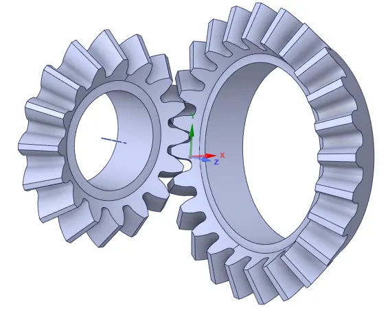
- Then, DOUBLE CLICK ON MODEL. This will open the mechanical module.
- In the Mechanical Module, first rename the gear geometry as Small gear and Big gear.
- Assign material as Structural steel to both the gears.
- Go to CONNECTIONS > CONTACTS > CONTACT FACES > TARGET FACES > TYPE = FRICTIONAL > BEHAVIOUR = SYMMETRIC > FORMULATION = AUGMENTED LAGRANGE > INTERFACE TREATMENT = ADJUST TO TOUCH.
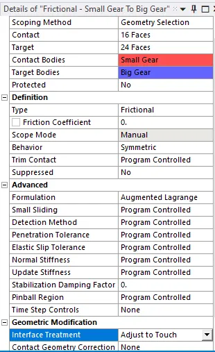
- Then, CONTACT > INSERT > JOINT > CONNECTION TYPE > BODY – GROUND > TYPE = REVOLUTE > SCOPE > APPLY.
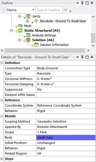
- This will introduce the gear as a revolute joint.
- Similarly, create another joint for Gear_2.
- Now, go to MESH > ELEMENT SIZE = 6MM > GENERATE MESH.
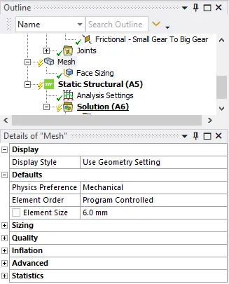
- MESH > INSERT > SIZING > ELEMENT SIZE = 1.75MM > SCOPE.
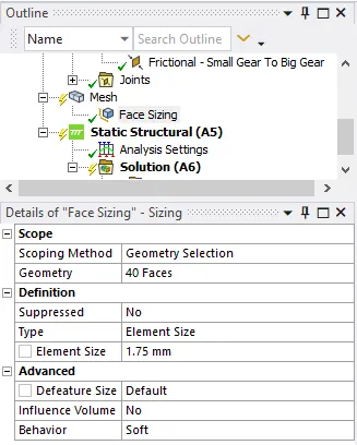
- Select the tooth faces of both the gear for sizing.
- This will create mesh on the geometry according to the element size.

- Now, go to STATIC STRUCTURAL > ANALYSIS SETTINGS > AUTO TIME STEPPING = ON > DEFINE BY = TIME > INITIAL TIME STEP = 0.1 > MINIMUM TIME STEP = 0.05 > MAXIMUM TIME STEP = 0.1 > LARGE DEFLECTION = ON.
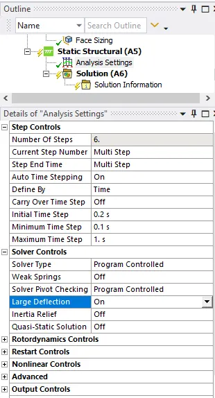
- Then, STATIC STRUCTURAL > INSERT > JOINT LOAD > JOINT = REVOLUTE –GROUND TO GEAR 1 > TYPE = ROTATION > MAGNITUDE = TABULAR DATA.
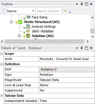
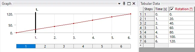
- Similarly, INSERT > JOINT LOAD > JOINT = REVOLUTE – GROUND TO GEAR 2 > TYPE = MOMENT > MAGNITUDE = -100NMM.
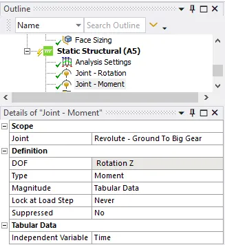
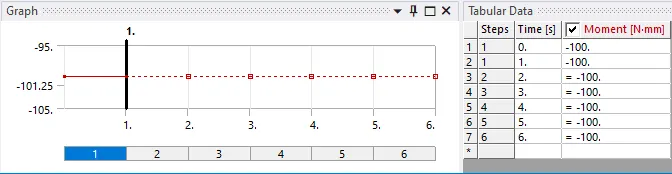
- Go to SOLUTION > INSERT > EQUIVALENT STRESS > ELASTIC STRAIN > TOTAL DEFORMATION.
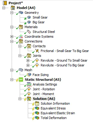
- This will define the output results.
- Go to SOLUTION > SOLVE.
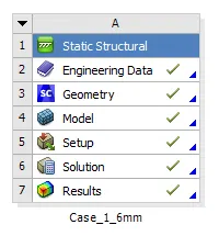
- The green tick mark defines that the solution is obtained.
- Case 2
- For second case, in the workbench window, CREATE DUPLICATE of the First case project.
- Now, all the Enginering data and the geometry is same as the first case.
- Open Mechanical module and go to MESH > ELEMENT SIZE > 5MM > GENERATE MESH.
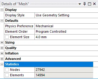
- This will define 5mm mesh size to the gears.
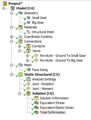
- All the steps are duplicated as in case 1.
- Now, go to SOLUTION > SOLVE.
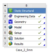
- The green tick mark defines that the solution is obtained.
- Case 3
- For second case, in the workbench window, CREATE DUPLICATE of the First case project.
- Now, all the Enginering data and the geometry is same as the first case.
- Open Mechanical module and go to MESH > ELEMENT SIZE > 4MM > GENERATE MESH.
- This will define 4mm mesh size to the gears.
- All the steps are duplicated as in case 1.
- Now, go to SOLUTION > SOLVE.
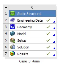
- The green tick mark defines that the solution is obtained.
RESULTS:
- Case 1:
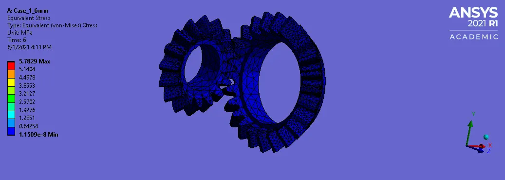
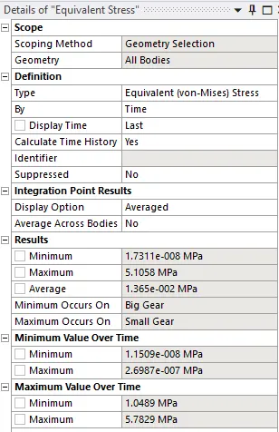
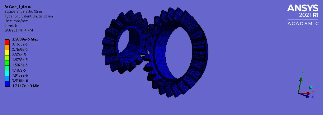
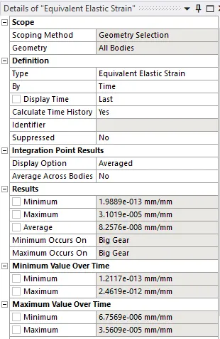
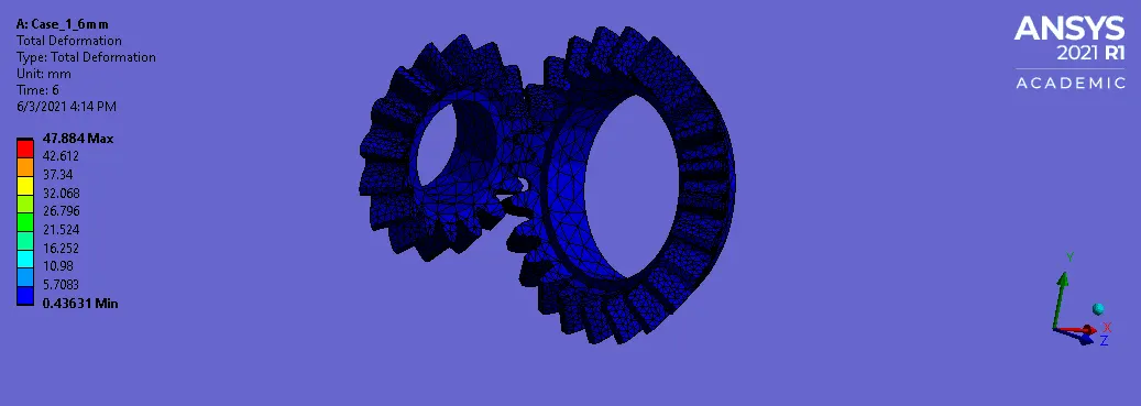
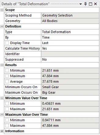
- Case 2:
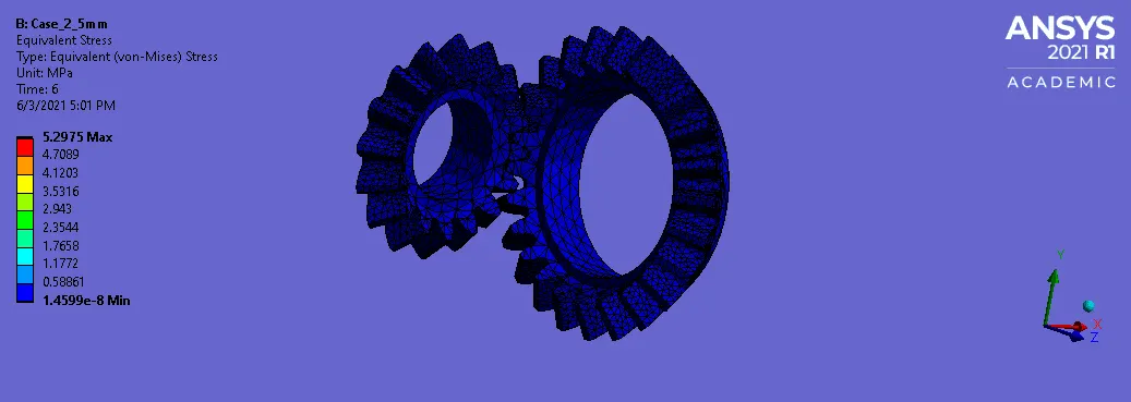
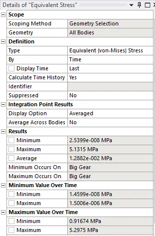
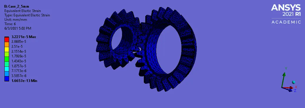
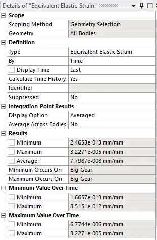
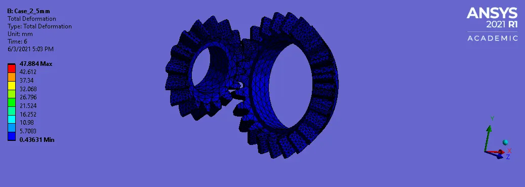
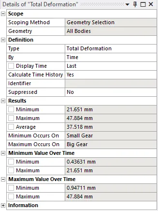
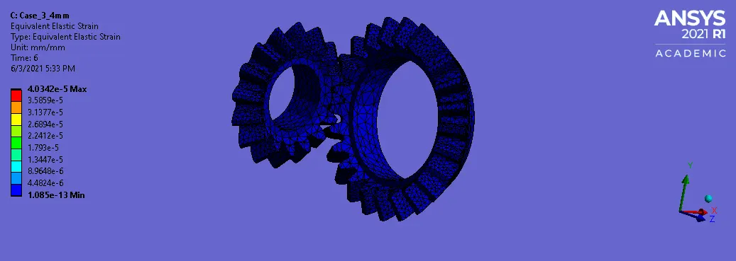
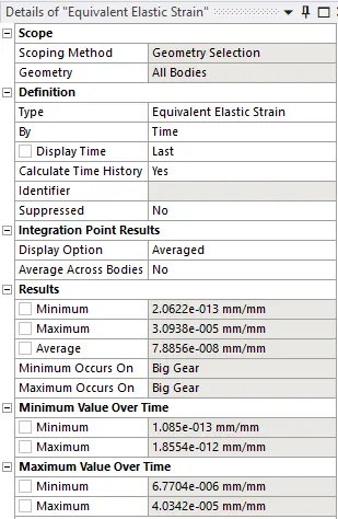
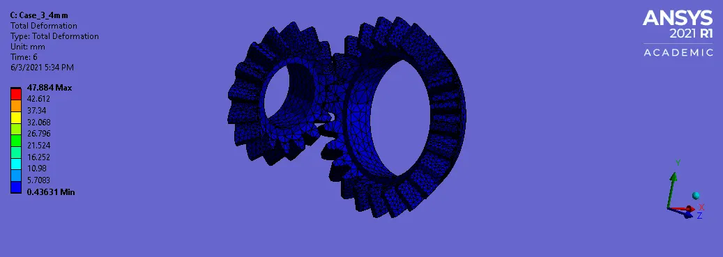
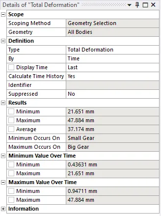
- Case 3:
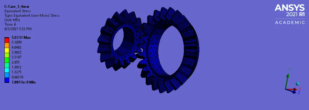
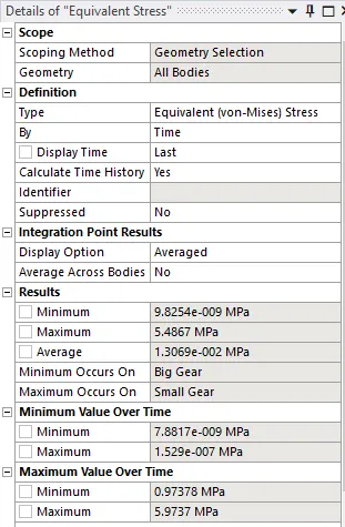
COMPARISION TABLE:
|
Stress (MPa) |
Deformation (mm) |
Strain (mm/mm) |
|
|
Case 1 - 6mm |
5.1058 |
47.884 |
3.1019e-05 |
|
Case 2 - 5mm |
5.1315 |
47.884 |
3.2271e-05 |
|
Case 3 - 4mm |
5.4867 |
47.884 |
3.0938e-05 |
- We can observe that, the stress values at 6mm, 5mm and 4mm elment size are increasing but they have a very less increment.
- The deformation values of all the cases remain same.
- The strain rates for the three cases have very less difference and are negligible as they are very small.
- Hence, we can say that the 4mm element size provides the best result outputs, though being not much difference.
- The values converge as we reduce the element size, but further more reduction in element size will only increase the simulation time.
LEARNING OUTCOMES:
- To insert conact faces.
- To insert revolute joints.
- To insert joint loads.
- To insert face sizing in meshing.
- The errors in ANSYS.
- The time steps.
CONCLUSION:
- Hence, by performaing this project we conclude that, the 4mm element size provide optimum results for the solution and the values converge.