Week 2 To perform analysis and grid dependency test on bevel gear in ANSYS
OBJECTIVE:- To perform analysis and grid dependency test on bevel gear in ANSYS
Grid dependency test:- It is to investigate how the solution depends on the grid size by running the simulation with refined mesh that is finer the mesh, higher is the accuracy of the result but with additional cost on computation time and computational power. Since, solutions are interpolated at the nodes to get an approximate result, higher the number of nodes and elements higher is the computational time and power required to complete the simulation.
So, the grid dependency test helps in determining optimal mesh size where the accurate result could be obtained keeping in the mind the cost of time and power. Since the result obtained are approximate,
Refining mesh further would result in negligible per cent change is the result but only increase the computational cost.
PROCEDURE:-
CASE 1- 4mm mesh size
- Open Ansys Workbench and choose static structural.
- In the Engineering data, let the material be structural steel with default values.
- For the geometry, right-click and import the given Bevel_Gear.igs and open the space claim to check it.
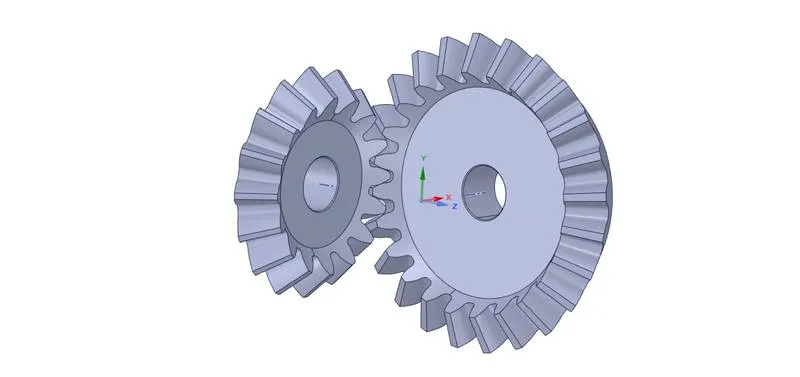
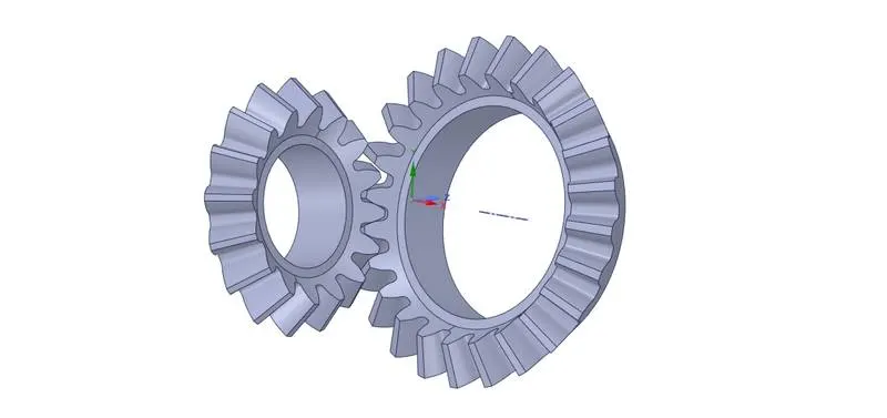
- The middle portion of both the gear can be deleted as it is not the area of concern in analysis point of view and also to limit the element and nodes after mesh, in spaceclaim design tool can be used to edit the gears.
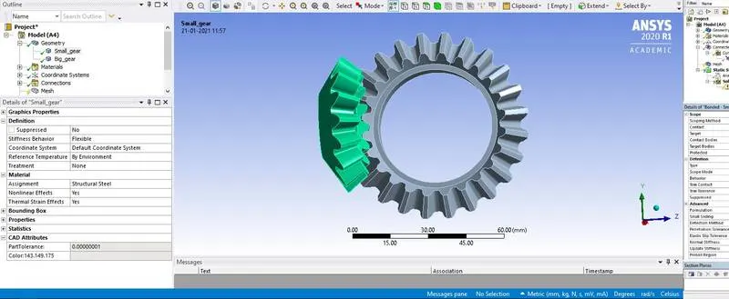
- Now in the workbench goto Model -> Edit, in the model window check the Geometry for the material and assign Structural Steel to both the part.
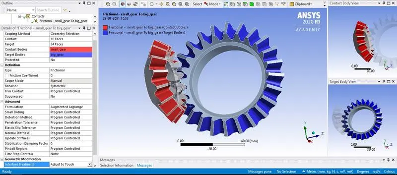
- Now for connection, choose the small gear as contact faces and big gear as target faces, Type= Frictional, Behaviour= Symmetric, Formulation= Augmented Lagrange and Interface Treatment= Adjust to touch
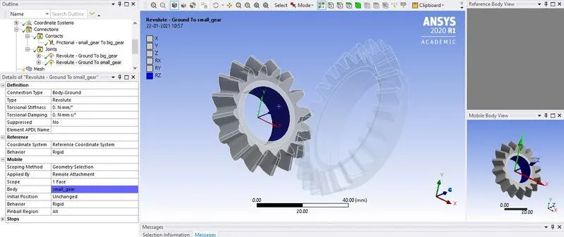
- For joints, right-click on Contacts -> insert -> joints, for both the gears connection type= Body-ground, type= revolute, scope= select respective faces of the gear
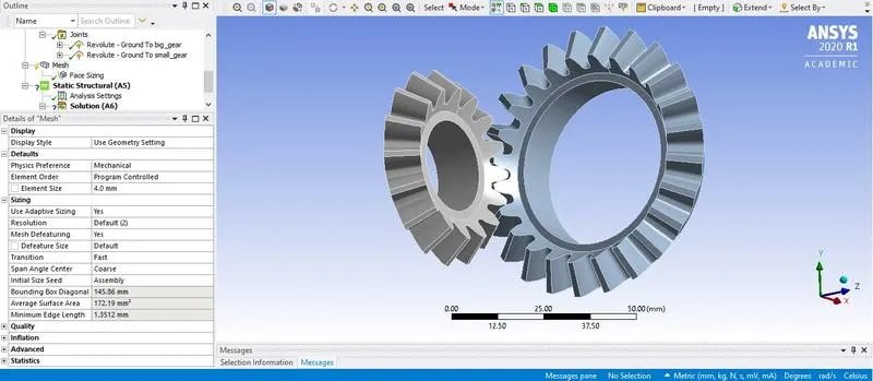
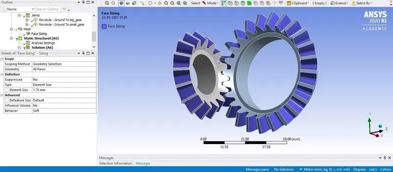
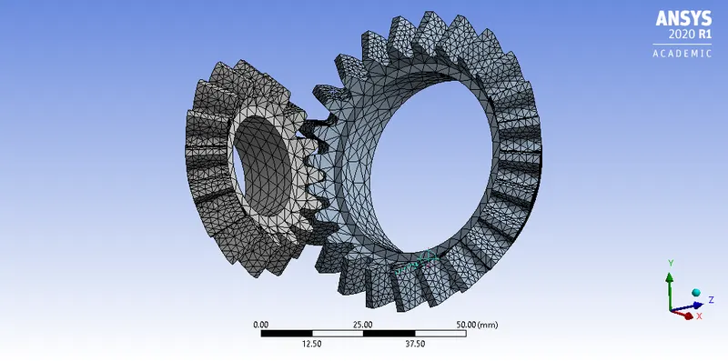
- For mesh, element size= 4mm and also mesh the teeth of the gear by element size= 1.75mm by selecting mesh -> insert -> sizing. Click on generate mesh to mesh the gear.
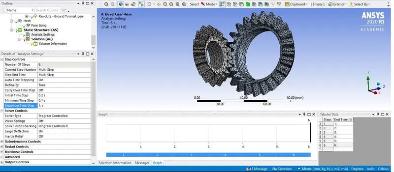
- For analysis setting, number of steps= 6 (select all the steps), Auto time stepping= On, Define by= Time, Initial time step= 0.2s, Minimum Time step= 0.1s Maximum Time step= 1s and Large Deflection= On
- For joint load, create 2 joint load for the 2 gears for the small gear provide rotation as the 20º angle difference from 0º to 120º and for the big gear provide moment of 100 Nm.
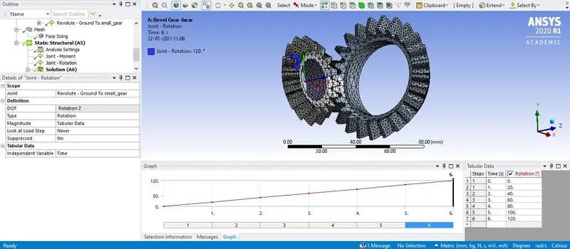
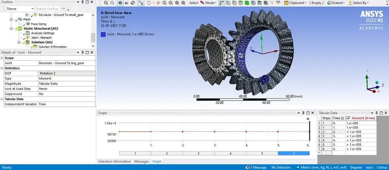
- Check the rotation of the 2 gear for clockwise and anticlockwise, the direction can be altered by providing -ve sign or changing the local coordinate of rotation gear.
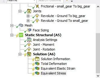
- Provide the required output request for the solution like total deformation, Von-Mises stress and Equivalent elastic strain and click on solve.
CASE 2- 5mm mesh size
- For the mesh size of 5mm, only change will be the change in the mesh Element size= 5mm.
CASE 3- 6mm mesh size
- For the mesh size of 6mm, only change will be the change in the mesh Element size= 6mm.
RESULT:-
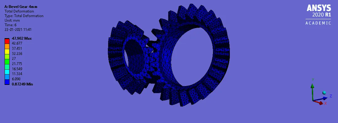
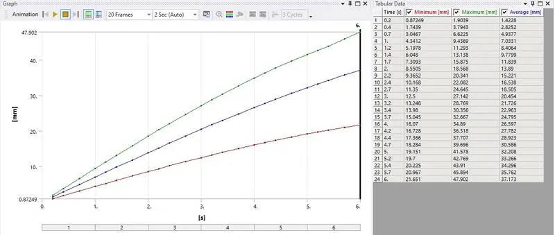
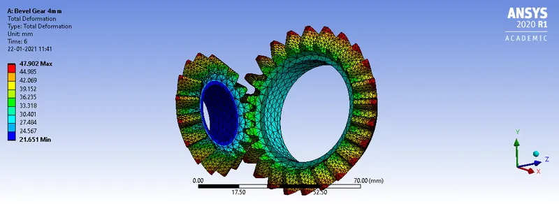
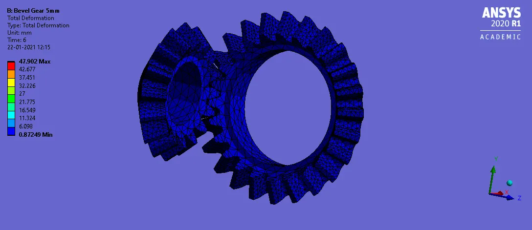
Total Deformation
CASE 1- 4mm mesh size
CASE 2- 5mm mesh size
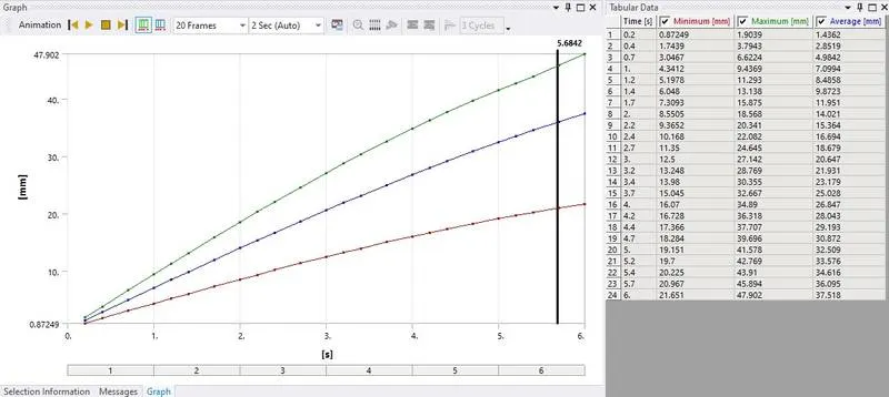
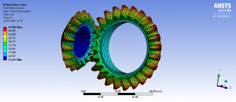
CASE 3- 6mm mesh size
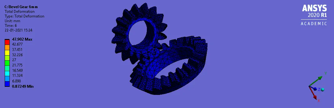
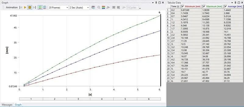
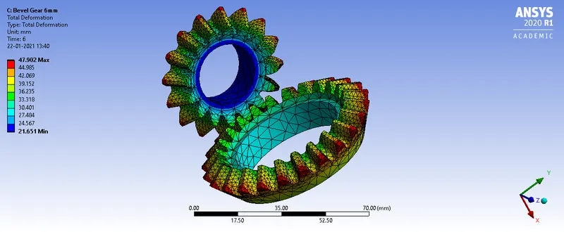
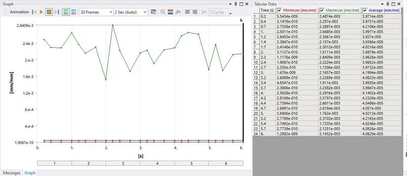
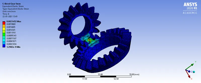
Equivalent Elastic Strain
CASE 1- 4mm mesh size
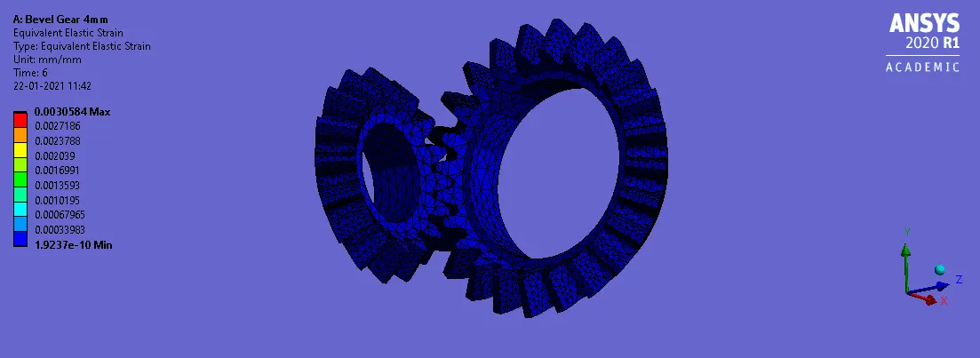
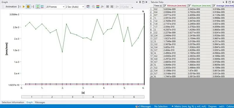
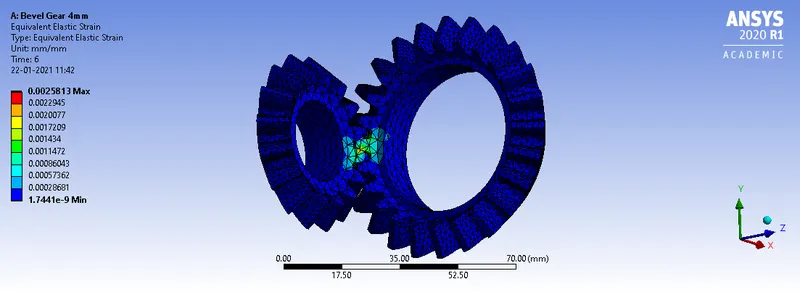
CASE 2- 5mm mesh size
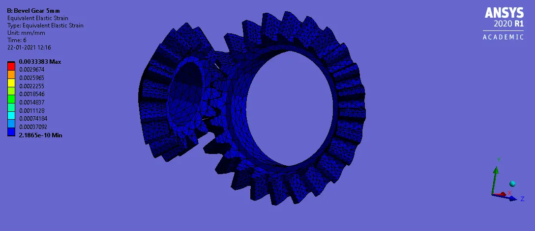
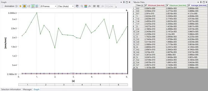
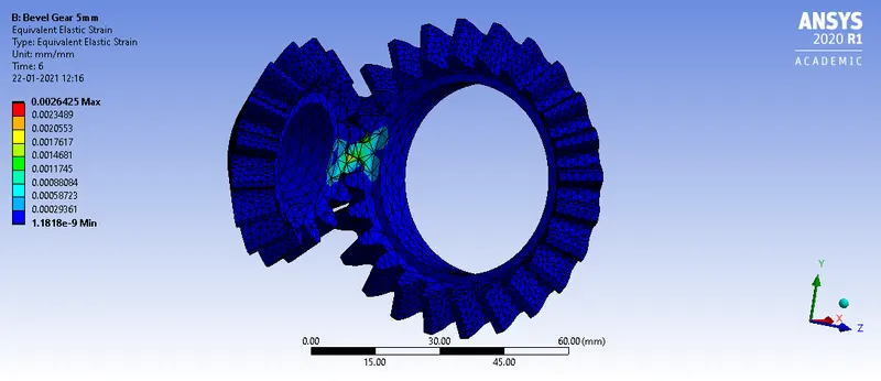
CASE 3- 6mm mesh size

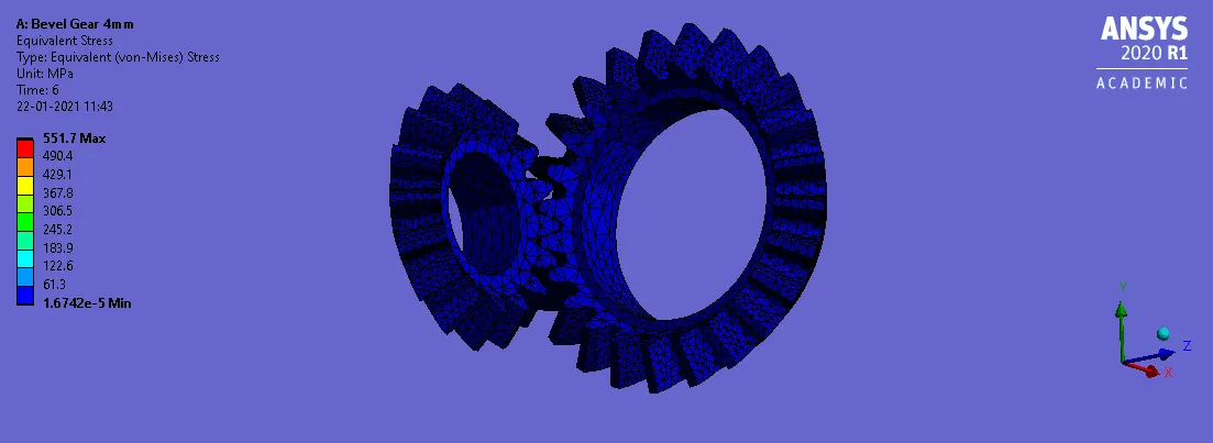
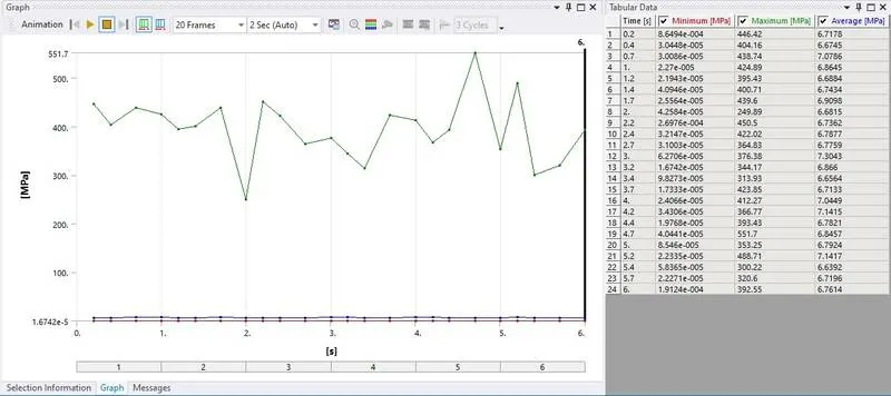
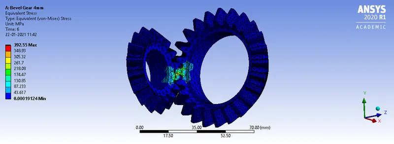
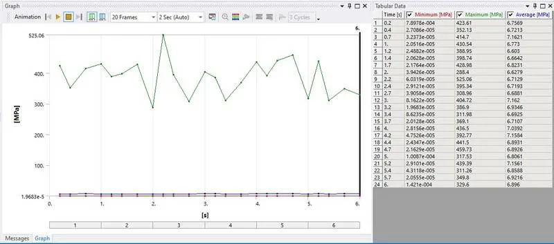
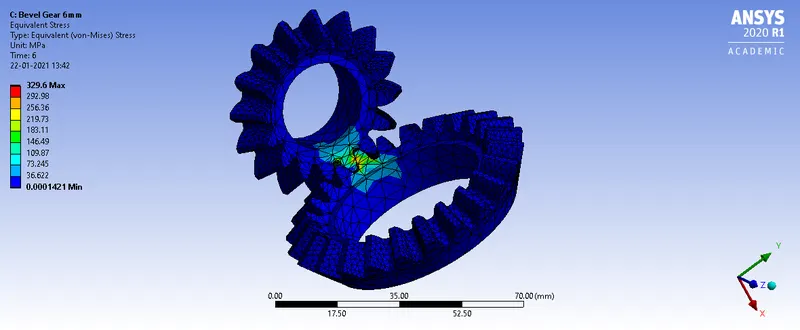
Equivalent Stress (Von-Mises)
CASE 1- 4mm mesh size
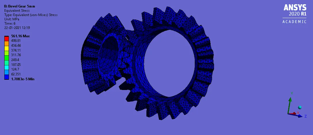
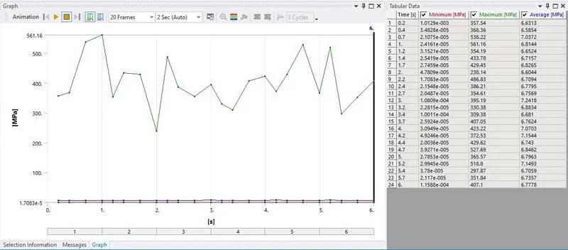
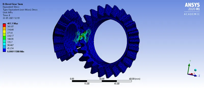
CASE 2- 5mm mesh size
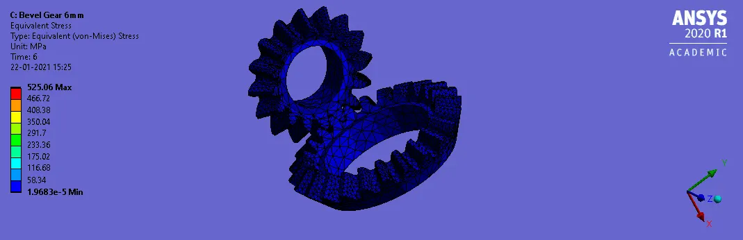
CASE 3- 6mm mesh size
Grid Dependency Test-
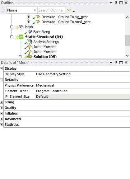
- For grid dependency test, set up the analysis same as above but the difference will be in the mesh click on the parameter for the element size and also for the maximum, minimum and average of the total deformation, Von-Mises stress and Equivalent elastic strain.
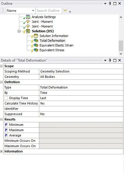
- Now in the workbench click on Parameter and provide the value of 4mm, 5mm and 6mm for the element size and click on Update All Design Points to solve for the output request.
| Name | P1 - Mesh Element Size | P2 - Total Deformation Minimum | P3 - Total Deformation Maximum | P4 - Total Deformation Average | P5 - Equivalent Elastic Strain Minimum | P6 - Equivalent Elastic Strain Maximum | P7 - Equivalent Elastic Strain Average | P8 - Equivalent Stress Minimum | P9 - Equivalent Stress Maximum | P10 - Equivalent Stress Average |
| Units | mm | mm | mm | mm | mm mm^-1 | mm mm^-1 | mm mm^-1 | MPa | MPa | MPa |
| DP 0 (Current) | 4 | 21.65063415 | 47.90235361 | 37.17287525 | 1.74E-09 | 0.002581276 | 3.95E-05 | 0.000191235 | 392.5493957 | 6.761414482 |
| DP 1 | 5 | 21.6506342 | 47.90228813 | 37.51769763 | 1.18E-09 | 0.002642518 | 4.00E-05 | 0.000115878 | 407.1026492 | 6.777767144 |
| DP 2 | 6 | 21.65063417 | 47.90229992 | 37.71979784 | 1.30E-09 | 0.002145209 | 4.06E-05 | 0.0001421 | 329.6003817 | 6.89599738 |
So by completing the analysis and the grid dependency test it can be inferred that by decreasing the mesh element size the accuracy of the output request is increased as it can be observed when the mesh element size decreases from 6mm to 4mm the resulting maximum stress and strain value accuracy is increases but further reducing the value of mesh size may result in negligible per cent change but only increase the computational cost.