Week 2 Bevel Gear Challenge
Objective:
To understand the signficance and use of grid dependancy in structural simulation and understand how to use parametric analysis.
Write a few words on what a grid dependency test is and its use.
Grid dependency test is to investigate how the solution depends on the grid size by running the simulation with multiple refined mesh i.e. finer the mesh, higher is the accuracy of the result. However, this results in additional cost on computation time and computational power. Since, solutions are interpolated at the nodes to get an approximate result, higher the number of nodes and elements higher is the computational time and power required to complete the simulation.
Grid dependency test helps in determining optimal grid size of the mesh and helps in eliminating redundancies of increasing mesh size more than the required size.
There are different mesh refinement techniques are used which has advantages and disadvantages and some depend on the experience and technical expertise of the FEA analyst. These techniques include- Reducing the element size, Increasing the element order, Global Adaptive mesh refinement, local adaptive mesh refinement, manually adjusting the mesh, Time adaptive mesh refinement, wavelength adaptive mesh refinement, etc.
Grid dependency test for Bevel Gear:
Step 1: Geometry Creation
The geometry was imported from the model of spur gears provided.

Step 2: Material Selection
Default material selected was stainless steel.
Properties for the material,
|
Density |
Young’s Modulus |
Poisson’s ratio |
Yield Strength |
Ultimate Tensile Strength |
|
|
Structural Steel |
7850 Kg m^-3 |
200 GPa |
0.3 |
250 MPa |
460 MPa |
Step 3: Meshing
Meshing has been done based on following parameters,
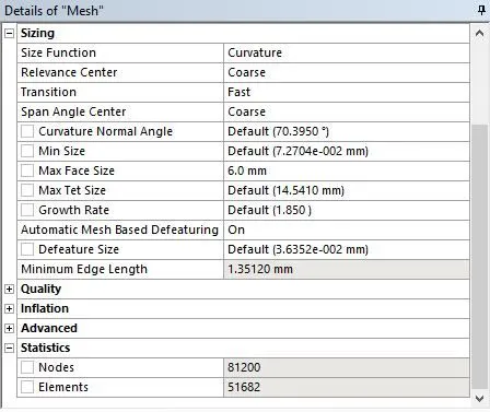
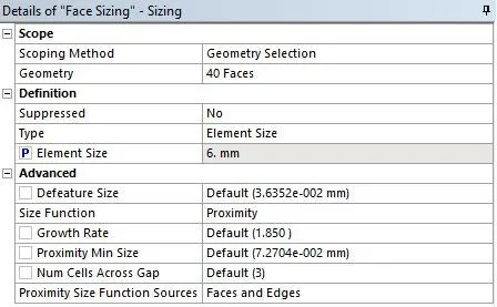
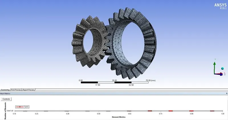
The mesh size was modified based on the size of element on the with mesh sizing option. All elements in contact are meshed with face sizing of parametric nature. 3 sizing parameters were considered in this analysis based on the problem viz, 4mm, 5mm, 6mm.
Step 4: Processing
Processing the model involves creation of connections, Joints, Bouindary conditions, Loads etc.
1. Creation of Connections:
Connections include creation of contacts as well as joints in this problem. By virtue of the model, Ansys considers the faces in contact as contact regions. However, during the course of simulation all faces of gear teeth will be contact regions and hence have to be considered.
Target body is selected as such that the contact body is not allowed to penetrate the target body but target body is free to penetrate. In present case, since both bodies are under consideration either can be considered as target and contact bodies.
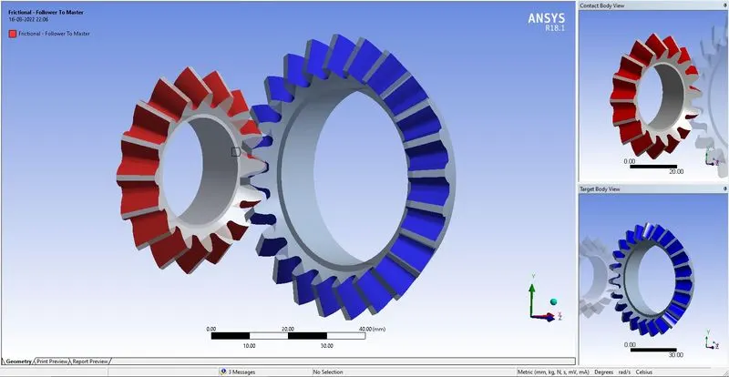
Connections are considered frictional and Adavanced lagrange formulation is considered for high stiffness and low penetration between gears.
Second part is creation of joints. Since both the gears are freee to rotate in z-direction, creation of revolute joint creates and axis for revolution of gears. Inner face of each gear is selected for creation of revolute joint.
2. Analysis settings:
Number of steps for convergence is increased from 1 to 6 so that we can observe stresses and strains at each step separately. The time step for iterations is set as,
- No. of steps- 6
- Auto time stepping- ON
- Defined by- time
- Initial time step- 0.1
- Minimum time step- 5E-2
- Maximum time step- 1
large deflections are allowed so as to limit any false stiffness creeping into the model unkown. Auto time stepping is switched ON and steps controls are defined by time instead of substeps.
3. Joint loads:
Joint loads are created for the two gears in order to induce motion in the bodies under study. Relative motion between bodies induce stresses in the gears which can be studied using this software.
The larger of the two gears has been named 'master' an the smaller one is considered 'slave'. The masrter gear is given a moment of 100 N-mm. The slave gear is given roation of 20 deg. in for each step of total 6 steps of the solution. To match the movement of each gear, the moment given to master gear is updated to -100 N-mm.
Step 5: Results and Post-Processing
The results in this simulation includestudy of stresses induced in all the 3 variations of meshes, strains in the gears and total deformtion values in the three instances of mesh sizes.
For demonstrating the work, the results of mesh size 6 has been considered, comparison of results for different mesh sizs shall be covered further.
1. Equivalent Stresses
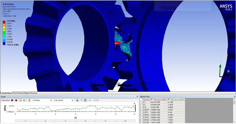
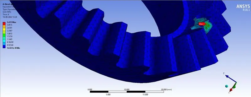
It can be observed that the max stresses induced is at the point of contact of the two gears. The value of stresses induced is 3.433 MPa. The gear teeth not in contact are free from any contact stresses and that can be observed in these results.
2. Equivalent Strain
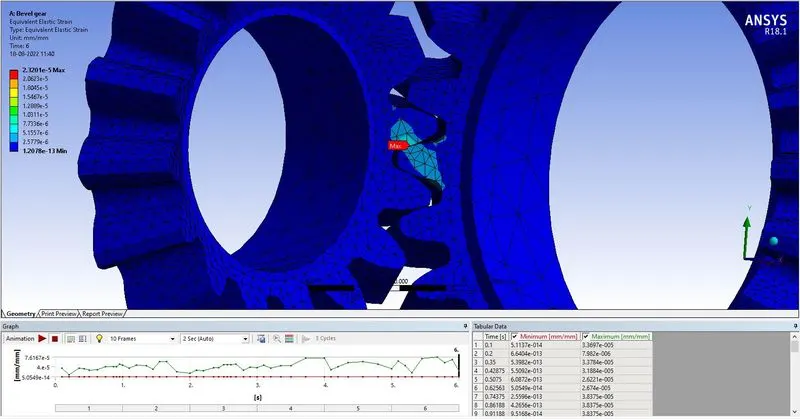
As strain is a result of stresses caused in a body, it can be observed that the location of max. strain is the same as the location of max. stress. The value of max strain is 2.32. Also, it can be observed that gear tooth not in contact are not under strain.
3. Total Deformation
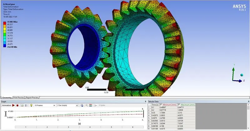
It can be observed that max deformation occurs at the outside end of the gear tooth. However, it should be noted that max stresses occurs near the inside end of teeth. This might seem inconsistent although expected. Since the outside end of gear experiences little stress, it offers smaller resistance to deformation at that location.
It can also be observed that the master gear shows more deformation at the inner radius than the slave gear. This is due to the smaller gear having higher stiffness, offers more resistance to any deformation.
Conclusion:
| Name | Face Sizing Element Size [mm] | Equivalent Elastic Strain Minimum [mm mm^-1] | Equivalent Elastic Strain Maximum [mm mm^-1] | Equivalent Stress Minimum [MPa] | Equivalent Stress Maximum [MPa] | Total Deformation Minimum [mm] | Total Deformation Maximum [mm] |
| DP 2 | 6 | 1.21E-13 | 2.32E-05 | 1.63E-08 | 3.433 | 24.25 | 47.88 |
| DP 3 | 5 | 1.18E-13 | 2.32E-05 | 1.58E-08 | 3.429 | 24.25 | 47.88 |
| DP 4 | 4 | 1.00E-13 | 2.23E-05 | 1.62E-08 | 3.36 | 24.25 | 47.88 |