Grid Dependency Test on Bevel Gear using Ansys
Grid Dependency Test
Meshing a component is the fundamental part of any FEA or finite element analysis. The basic idea behind meshing is to reduce the degree of freedom of the system from infinite to finite. Any component has an infinite number of atoms. Thus, if the atoms are considered as the points for calculation the equations, then there would be an infinite number of equations to solve, depending on degree-of-freedom. But if these calculation points are reduced to some finite number of points, then the result would be approximated or nearby.
FEA works on approximation. If the number of points, called nodes, are increased the result would be closer to the true value. However, it would cost more. The reason is, when the density of the nodes is increased, the number of equations to solve would increase, and this would cause more computational time.
Therefore, in finite element analysis, there is always a compromise between the required mesh density and the available computational time.
Now, as discussed earlier, when the density of the mesh is increased the result would drift towards the true value. Obviously, when FEA was checked by reducing the element size, at some point, there wouldn’t be any significant change in the value of the results. This procedure of checking the final value of element size is called the grid dependency test.
Objective
- To mesh the bevel gear model.
- To apply the boundary conditions.
- To do the analysis setting.
- Evaluate the results.
- To find out the stress, equivalent elastic strain, and deformation.
- To carry out this simulation in three different cases, using 6 mm, 5 mm, and 4 mm element size.
Procedure
For simulating this case, the Static Structural module was chosen, for one case.
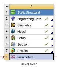
Figure 1: Static Structural module was chosen for this work.
For simulating this case, the Static Structural module was chosen. In those modules, in Engineering Data, Structural Steel was the default material. It was kept as it is, as the material does not affect the stress concentration.
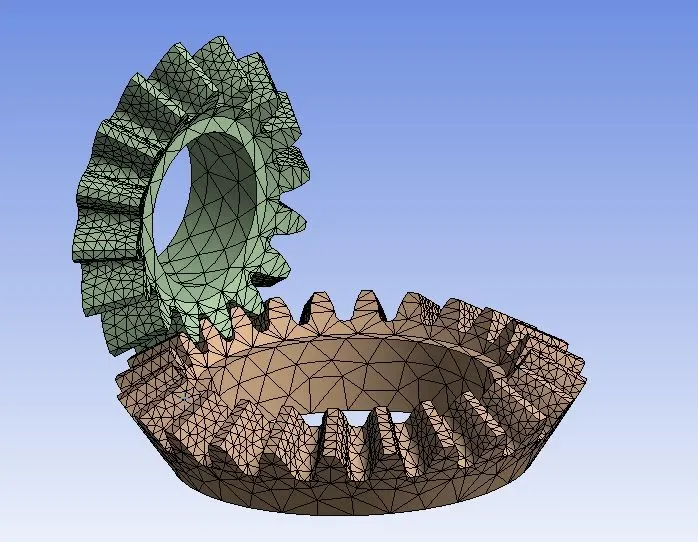
Figure 2: Bevel gear with a mesh size of 6 mm, and face sizing of 1.75 mm.
Now, using the Model section of the Static Structural module, both of those parts were first assigned with the structural steel material. In the mesh part, since the teeth were the area of interest, therefore, face sizing option was used on the face of the teeth, with the size of 1.75 mm. The other element size was kept equal to 6 mm. The element size was set as parametric, to solve other cases.
Boundary Conditions
Contact
In boundary conditions, firstly, the contact had to define. The Ansys automatically found out the neighboring faces of different bodies and created a bonded contact between them. But when the gear rotates, all of its teeth come in contact one after another. This information had to be input manually, therefore, the existing contact card was modified, and all the surfaces that could come in contact while rotating were selected, and made a friction contact between them. In the figure shown below, in the top left corner, it can be observed that one gear is the contact body, and the other is the target body. Now, because it was unsure which is master and which is slave, the behavior of formulation was kept as symmetric. Also, the contact formulation was selected as Augmented Lagrange. It is because, it ensures extra stiffness, and thus less penetration.
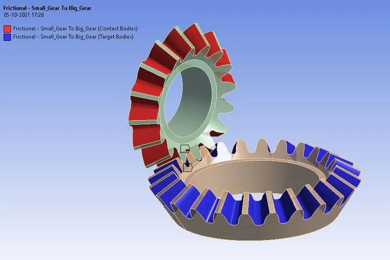
Figure 4: Contact defined for two gears.
Joint
After contact, a revolute joint had to define for both gears. Thus, it was created with, connection type as Body-Ground.
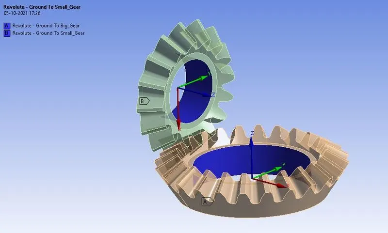
Figure 5: Revolute joint for two gears.
In the analysis set, the number of steps was divided into 6 steps. Then, the joint load was applied to both the gears. The load for smaller gear was defined in tabular form as shown below.

Figure 6: Rotational joint load to smaller gear.
The second gear is the joint load in terms of the moment, equal to 100 N-mm.

Figure 7: Moment to bigger gear.
For solving every 3 cases viz. mesh with 6 mm, 5 mm, and 4mm, the input and output parameters were set to parametric. In input, the element size, and in the output, equivalent (v-m) stress, equivalent elastic strain, and total deformation were set to parametric.
After setting, the input and output parameters, the parameter section was opened, in which the first case with a 6 mm element size was already present. Along with that, two more rows were added for the 5 mm, and 4 mm element sizes. The parameter section was then hit to update. The solver started solving the problem in the background. And the result can be seen in the figure below.
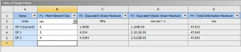
Figure 8: Result of the three cases on one platform.
The figures below shows result contours.
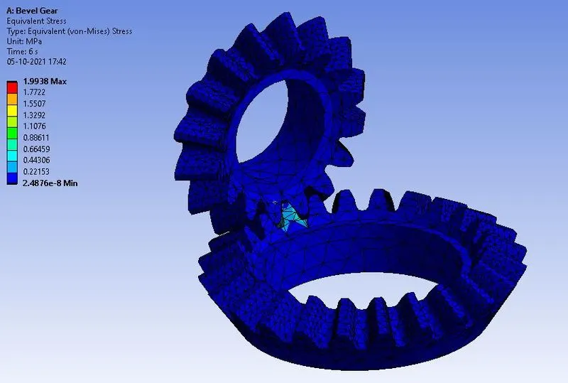
Figure 9: Von-Mises contour of the bevel gear with 6 mm element size.
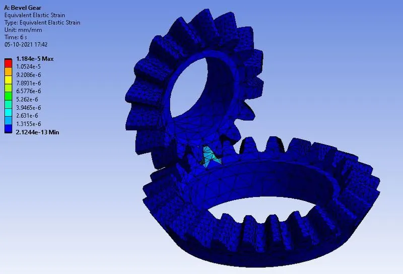
Figure 10: Equivalent elastic strain contour of the bevel gear with 6 mm element size.
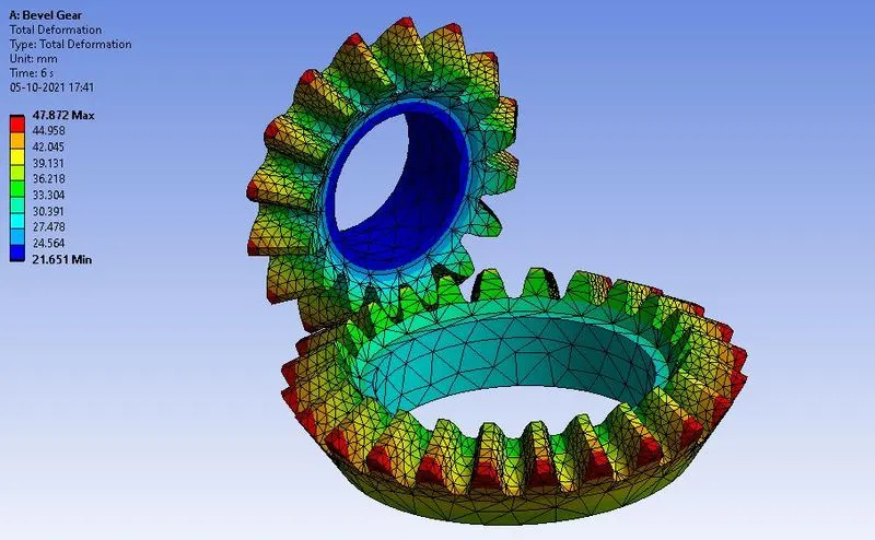
Figure 10: Total deformation contour of the bevel gear with 6 mm element size.
From fig. 8, it can be observed that the deformation in the result is almost the same, however, there is a significant change in the equivalent Von-Mises Stress and equivalent elastic strain. As the size of the element was reduced from 6 mm to 5 mm, there is a significant change in the equivalent Von-Mises Stress, from 1.99 MPa ~ 2 MPa to ~ 4MPa, respectively. Also, there is an increase in elastic strain by 0.92E-05 mm/mm. Further, when it was reduced to 4 mm, the Von-Mises stress was again increased to approx. 4.5 MPa and the elastic strain was increased 0.43E-05 mm/mm. This shows that how the decrease in size of an element affects the result and reaches the true value. From 6 mm to 5 mm, the stress changed by approx. 2.5 MPa i.e., 125% increase, but from 5 mm to 4 mm it changed by just 0.5 MPa i.e., just 12.5% increase. Thus, it can be said that it has reached close to the true value. Thus, 4 mm or 3 mm can be taken as the element size for the requirement of a more accurate result.
CONCLUSION
In this work, three cases were compared, differing in element size. In the first case, the mesh size was 6 mm, in the second it was 5 mm, and in the third case, it was 4 mm. After performing the simulation, it is found that when the element size was reduced from 6 mm to 5 mm, there was a significant change in the result. However, when it was further reduced from 5 mm to 4 mm, the result deviated slightly. Thus, it can be said that it has reached a closer value. This is how the grid dependency test was performed on the bevel gear.