Simulink Model of Doorbell & a Heater
Week 2 Challenge in SIMULINK
AIM:
(1) Create a Simulink model of Doorbell using solenoid block with the given details.
(2) Create a Simulink model to make the use of a thermistor to sense the temperature of a heater & turn on or turn off the fan as per the given conditions.
SOLUTIONS:
(1) Doorbell Model using solenoid block:
Given conditions:
In the arrangement, when the switch is closed the electromagnet receives electrical power from the battery and pulls the metal arm to hit the bell producing sound by creating a situation where the switch is closed for 2 seconds and then released.
Blocks used:
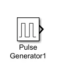
(i) Pulse generator:
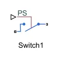
(ii) Physical Signal (PS) switch:
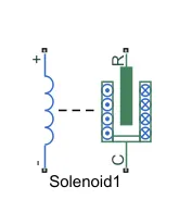
(iii) Solenoid:
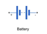
(iv) Battery:
(v) PS-Simulink & Simulink-PS convertors:
(vi) Ideal Translational Motion Sensor:
(vii) Display:
(viii) Scope:
(ix) Electrical & Mechanical reference:
(x) Solver Configuration:
Procedure:
(i) We use pulse generator to provide input to the system with given condition of 2 second delay. Also pulse width is defined w.r.t to the percentage of the time for one cycle.
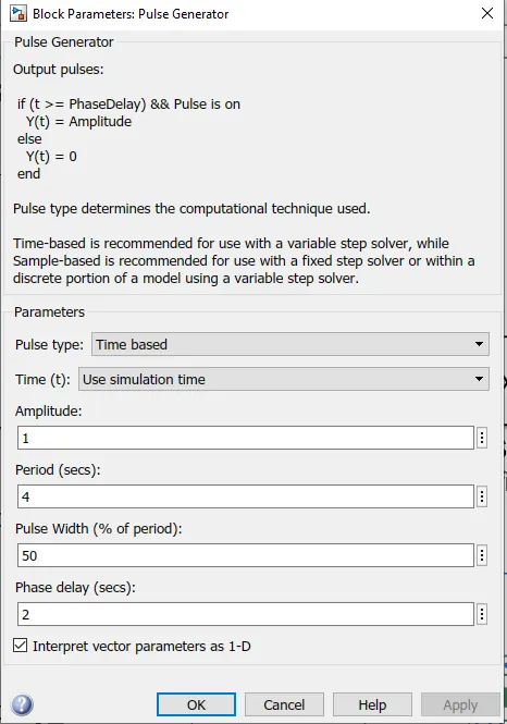
fig (1). Pulse generator input parameters
(ii) A Physical signal block represents a switch controlled by the input from the pulse generator. If the external physical signal PS is greater than the threshold, then the switch is closed, otherwise the switch is open.
(iii) Solenoid is used to pull the metal arm to hit the bell by supply is provided via batteries. Batteries are connected in series to for more current.
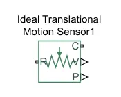
(iv) To check the motion of the plunger, we need to add 'Ideal Translational Motion Sensor' block which will show displacement & velocity of the plunger.
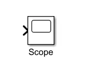
(v) To display the output in the graphical & digital way, we add 'scope' & 'display' blocks.
(vi) PS-Simulink & Simulink-PS convertors are use to converts the Phyical signals to simulink output signals.
(vii) Electrical & Mechanical reference are conneted as the reference point,i.e., a frame or a ground.
(viii) Solver configuration is used to defines solver settings to use for simulation.
Circuit layout diagram:
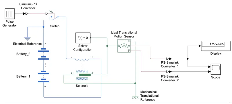
fig (2). Circuit layout diagram of doorbell mechanism
Results:
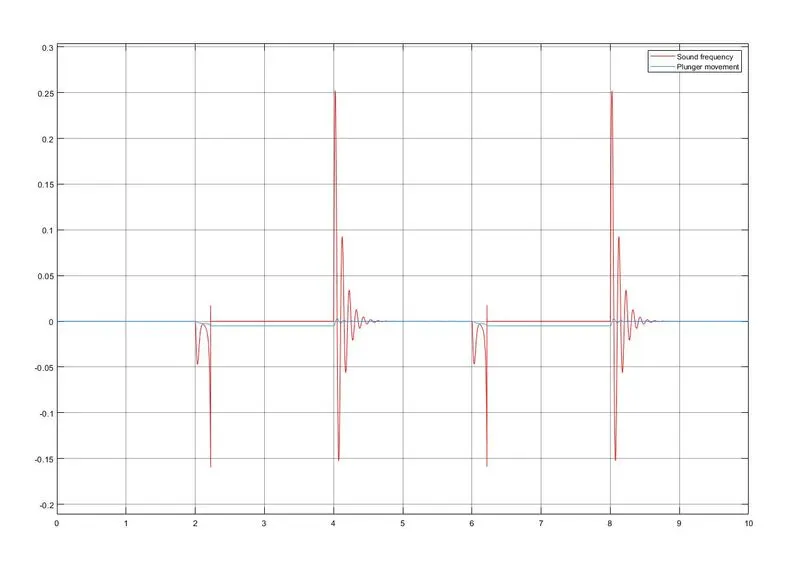
fig (3). Ouput graph showing the velocity & displacement of the plunger
(2) Heater using thermistor:
Given conditions:
| Time(sec) | Temperature(°C) | Fan Condition |
| 0-10 | 20 | OFF |
| 10-30 | 27 | ON |
| 30-50 | 23 | OFF |
Fan conditions: If the temperature above 25 °C then the fan is ON, otherwise it is OFF.
Blocks used:
(i) Signal Builder:
(ii) Controlled Temperature source:
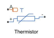
(iii) Thermistor:
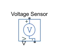
(iv) Voltage Sensor:
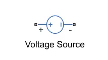
(v) Voltage Source:
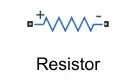
(vi) Resistor:
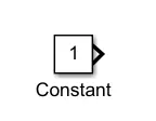
(vii) Constant:
(viii) Scope:
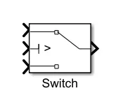
(ix) Switch:
(x) PS-Simulink & Simulink-PS convertors:
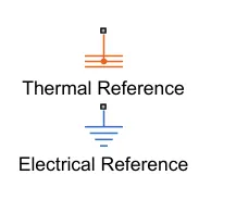
(xi) Thermal & Electrical reference:
(xii) Solver configuration:
Procedure:
(i) In this problem, we have to display the output graph using a thermistor to sense the temperature of a heater & turn on or turn off the fan as per above mentioned conditions.
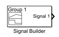
(ii) To provide the input, we have used the 'Signal Builder' block to assign the temperature value w.r.t. time range. The signal builder can be easily manipulated as per our need.
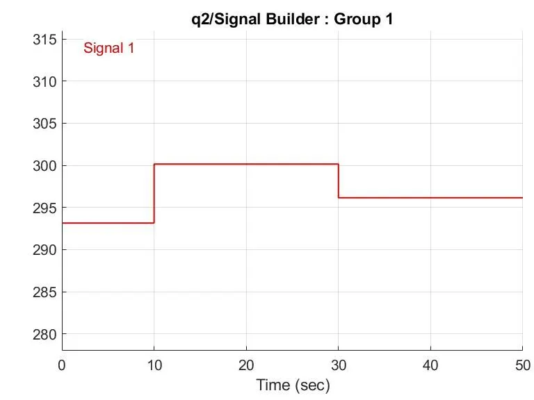
fig (4). Signal builder as per the given conditions
(iii) A Simulink-PS converter is used to convert the simulink input to the physical signals.
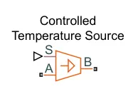
(iv) A controlled temperature source is used as an ideal energy source in a thermal network that can maintain a controlled temperature difference regardless of the heat flow rate. The temperature difference is set by the physical signal port S. A positive temperature difference causes the temperature at port B to be greater than the temperature at port A.
(v) The output port B of the is conneted to the thermistor's input port A. To operate the thermistor, we need to use DC voltage source with a resistor.
(vi) To switch the fan ON/OFF, a voltage sensor is used attached to the thermistor's negative side and the voltage is being measure and signals are passed to the run the given fan ON/OFF condition w.r.t. temperature condition,i.e. 25 °C.
(vii) Switch is attached to display the output of the fan condition, with two constants `1 & 0`.If the value of temperature is below 25 °C,i.e. for 0-10 secs the fan is off and switch is at `0` and when it crosses the threshold temperature 25 °C, the signal sent is `1` and the fan is ON . To display the output on the scope, we need to use PS-Simulink convertor to converts the Phyical signals to simulink output signals.
(viii) Thermal reference block represents a reference point in a thermal network where the temperature is equal to absolute zero. And electrical reference are conneted as the reference point,i.e., a ground.
(ix) Solver configuration is used to defines solver settings to use for simulation.
Circuit layout diagram:
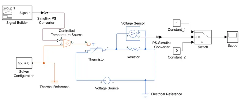
fig (5). Circuit layout of the heater using thermistor
Results:
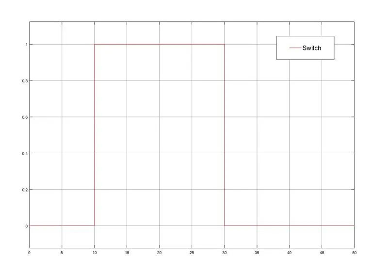
fig (6). Ouput graph fan state for the given condition
CONCLUSION: Successfully created the block daigram of the doorbell and the heater with the given conditions to perform the output using Simulink under MATLAB.