Week -2
Aim
To Make a Simulink model of Doorbell using solenoid block
Objective
Analyze the physical movement of the plunger by creating a simulation where the switch is closed for 2 seconds and then released.
Door bell
A doorbell works on the principle of electromagnetism. When you press the doorbell button, an electric current flows through a coil of wire around an iron core. This creates a magnetic field, which attracts a metal plunger. The plunger is connected to a bell, so when it is pulled towards the electromagnet, it strikes the bell and produces a sound.
Here is a more detailed explanation of the working principle of a doorbell:
When the doorbell button is pressed, an electric circuit is completed, and current flows from the battery through the switch and the coil of wire around the iron core.
The current flowing through the coil of wire creates a magnetic field.
The magnetic field attracts the iron plunger.
The plunger is connected to a bell, so when it is pulled towards the electromagnet, it strikes the bell and produces a sound.
As soon as the doorbell button is released, the circuit is broken and the current stops flowing.
The magnetic field disappears, and the plunger is returned to its original position by a spring.
Door bell Simulink Model
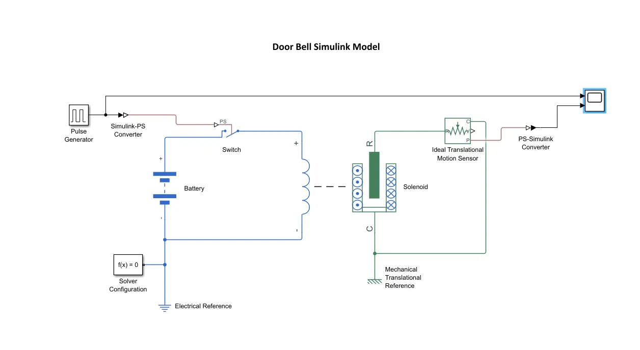
Model Description:
The Simulink model of a doorbell using a solenoid block consists of the following blocks:
Pulse Generator: This block generates a square wave pulse with a period of 4 seconds and a pulse width of 2 seconds. This pulse is used to represent the switch being closed for 2 seconds and then released.
Electrical Reference: This block represents the electrical ground.
Battery: This block represents a 12V battery.
Solenoid Block: This block represents a solenoid.
Mechanical Reference: This block represents the mechanical ground.
Ideal Translational Sensor: This block measures the displacement of the solenoid plunger.
Scope: This block displays the displacement of the solenoid plunger over time.
Model Simulation:
To simulate the model, simply click the "Run" button. The model will run for 10 seconds.
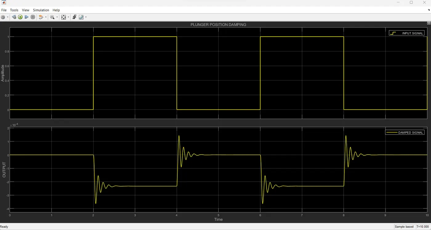
Observations:
The following observations can be made from the model simulation:
- The solenoid plunger is displaced when the switch is closed.
- The solenoid plunger returns to its original position when the switch is released.
- The displacement of the solenoid plunger is proportional to the voltage applied to the solenoid.
Thermistor
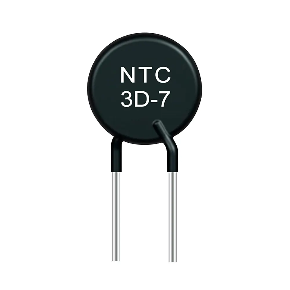
A thermistor is a semiconductor device that exhibits a large change in electrical resistance when its temperature changes. Thermistors are widely used as temperature sensors, but they can also be used for other purposes, such as flow measurement, liquid level sensing, and self-heating.
There are two main types of thermistors: negative temperature coefficient (NTC) thermistors and positive temperature coefficient (PTC) thermistors. NTC thermistors decrease in resistance as their temperature increases, while PTC thermistors increase in resistance as their temperature increases.
Thermistor Model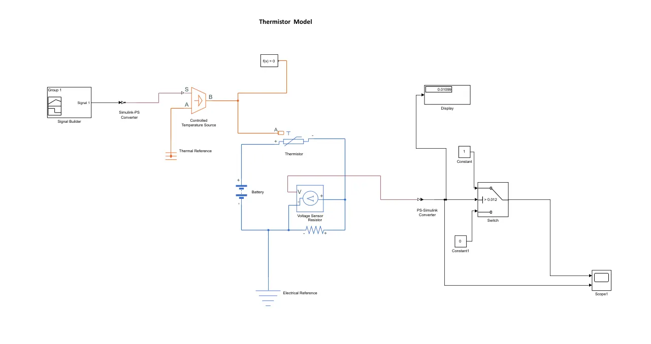
Signal builder
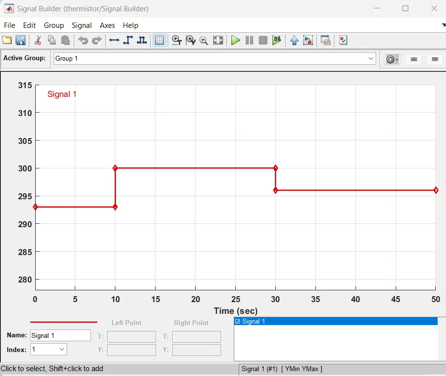
The Signal Builder block in Simulink is used to create custom waveforms.
The signals are created based on the input conditions;
- 0 to 10 sec - 20 deg C (293.15 K)
- 10 to 30 sec - 27 deg C (300.15 k)
- 30 to 50 sec - 23 deg C (296.15 k)
The time rage of the signals are assigned from 0 to 50 seconds and the signals are builded based on the temperature ranges.
Simulink PS Converter
The Simulink-PS Converter block is used to convert Simulink signals into physical signals. This allows Simulink models to be connected to Simscape physical networks.
Controlled temperature source
This block represents an ideal energy source in a thermal network that can maintain a controlled temperature difference regardless of the heat flow rate.
Thermal reference
This block represents a reference point in a thermal network where the temperature is equal to absolute zero.
Thermistor
The Thermistor block in Simulink is used to model the behavior of a thermistor. Thermistors are temperature-sensitive resistors whose resistance changes with temperature. They are used in a variety of applications, including temperature measurement, temperature compensation, and temperature control.
Battery
The Battery block in Simulink is used to model the behavior of a battery. Batteries are electrochemical devices that convert chemical energy into electrical energy. They are used in a variety of applications, including electric vehicles, portable devices, and renewable energy systems.
Electrical reference
Electrical reference port. A model must contain at least one electrical reference port (electrical ground).
Voltage Sensor
The block represents an ideal voltage sensor, that is, a device that converts voltage measured between any electrical connections into a physical signal proportional to the voltage.
Connections + and - are conserving electrical ports through which the sensor is connected to the circuit. Connection V is a physical signal port that outputs voltage value.
PS-Simulink Converter
The PS Simulink converter is a tool that allows you to convert Simulink models into Simscape physical networks. This allows you to simulate the behavior of complex physical systems in Simulink.
Switch Block
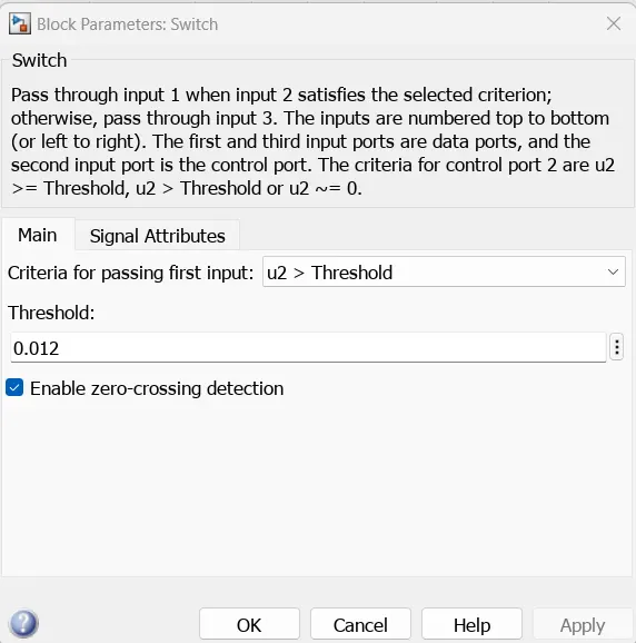
The Switch block in Simulink is used to select between different input signals. It has multiple input ports and a single output port. The output port is connected to one of the input ports.
Threshold value is set to 0.0012
Display
Display input values. If the incoming signal is of type string, the 'Numeric display format' parameter selection does not affect the display of the string.
Scope
In Simulink, a scope block is used to view the waveforms of signals. It can be used to display the waveforms of one or more signals, and it can also be used to display the waveforms of signals that are generated by different subsystems in a model.
Output 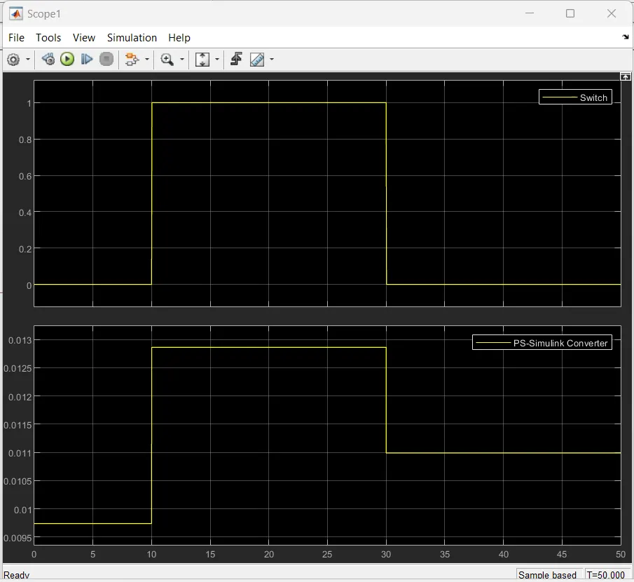
Conclusion
The Simulink model of a doorbell using a solenoid block and a thermistor to control a fan was successfully created and simulated. The results show that the doorbell works as expected, with the solenoid plunger moving to hit the bell when the switch is closed and the fan turning on when the temperature exceeds 25 °C.
The model can be used to study the behavior of the doorbell and fan system under different conditions, such as different temperature profiles or different switch closure durations. It can also be used to design and test control algorithms for the system.
Specific observations:
- The doorbell plunger moves to hit the bell when the switch is closed and remains in the "hit" position until the switch is opened.
- The fan turns on when the temperature exceeds 25 °C and remains on until the temperature drops below 25 °C.
- The temperature profile of the heater follows the specified steps (20 °C from 0 to 10 seconds, 27 °C from 10 to 30 seconds, 23 °C from 30 to 50 seconds.