Project 2 - Rankine cycle Simulator
Aim
Create a Rankine Cycle Simulator using MATLAB.
Objective
Calculate the state points of the Rankine Cycle
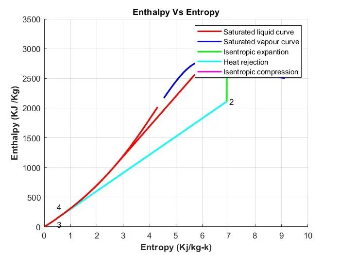
To plot the corresponding T-s and h-s plots for the given set of inputs
Introduction
The Rankine cycle is an idealized thermodynamic cycle of a heat engine that converts heat into mechanical work while undergoing a phase change. It is an idealized cycle in which friction losses in each of the four components are neglected. The heat is supplied externally to a closed loop, which usually uses water as the working fluid.
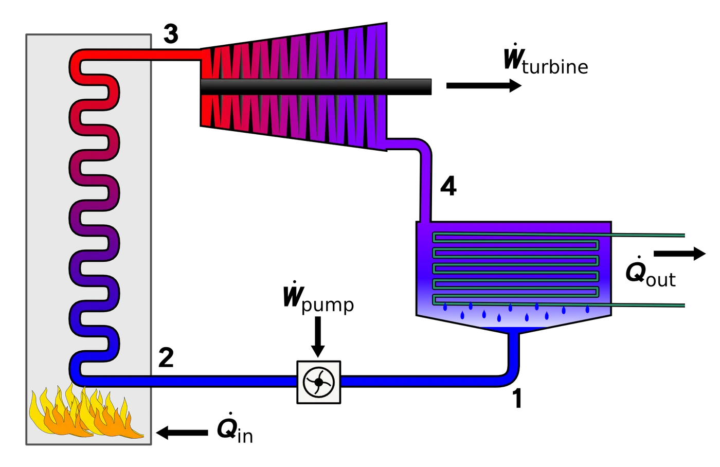
There are four processes in the Rankine cycle. The states are identified by numbers in the T–s diagram.
- Process 1–2: The working fluid is pumped from low to high pressure. As the fluid is a liquid at this stage, the pump requires little input energy. Process 1-2 is isentropic compression.
- Process 2–3: The high-pressure liquid enters a boiler, where it is heated at constant pressure by an external heat source to become a dry saturated vapour. The input energy required can be easily calculated graphically, using an enthalpy–entropy chart (h–s chart, or Mollier diagram), or numerically, using steam tables or software. Process 2-3 is constant pressure heat addition in boiler.
- Process 3–4: The dry saturated vapour expands through a turbine, generating power. This decreases the temperature and pressure of the vapour, and some condensation may occur. The output in this process can be easily calculated using the chart or tables noted above. Process 3-4 is isentropic expansion.
- Process 4–1: The wet vapour then enters a condenser, where it is condensed at a constant pressure to become a saturated liquid. Process 4-1 is constant pressure heat rejection in condenser.
The efficiency of a simple Rankine cycle can be written as

Each of the next four equations is derived from the Energy and mass balance for a control volume.  defines thermodynamic efficiency of the cycle as the ratio of net power output to heat input. As the work required by the pump is often around 1% of the turbine work output, it can be simplified.




When dealing with the efficiencies of the turbines and pumps, an adjustment to the work terms must be made:


% Code for Rankine cycle simulator
clear all
close all
clc

% Print Process Description
fprintf('l-2 Isentropic Expansion in Turbine\n ')
fprintf('2-3 Isobaric heat rejection in Condensor\n ')
fprintf('3-4 Isentropic Compression in Compressor\n ')
fprintf('4-1 Isobaric heat addition in Boiler\n')

% Entering the input data for calculation of state points
p1= 30;   %Pressure at Turbine Inlet in Bar
T1=400;   %Temperature at Turbine Inlet in Degree Celcius
p2=0.05;  %Pressure at turbine outlet in bar

% Taking data from Xsteam file for state point 1
h1 = XSteam('h_pT', p1, T1);
s1 = XSteam('s_pT', p1, T1);

% Taking data from Xsteam file for state point 2
s2 =  s1;                    % Because of Isentropic Expansion
sf2 = XSteam('sL_p',p2);     % saturated liquid entropy at pressure 2
sg2 = XSteam('sv_p', p2);    % Saturated vapour entropy at pressure 2
x2 = (s2-sf2)/(sg2-sf2);     % Vapour Fraction at state point 2
hf2 = XSteam('hL_p',p2);     % saturated liquid Enthalpy at pressure 2
hg2 = XSteam('hv_p' , p2);   % Saturated vapour Enthalpy at pressure 2
h2 = hf2 + (x2*(hg2-hf2));   % Enthalpy at state point 2

% Taking data from Xsteam file for state point 3
p3 = p2;	              % Constant Pressure heat removal process
s3=XSteam('sL_p',p3);     % saturated liquid entropy at Pressure 3
h3=XSteam('hL_p',p3);     % saturated liquid Enthalpy at Pressure 3

% Taking data from Xsteam file for State point 4
s4=s3;	% Isentropic Compression process
p4=p1;	% Constant Pressure heat rejection

% Work done in Turbine for the rankine cycle
W_T = h1-h2;

% Work done required for pump
v3 = XSteam ('vl_p' ,p3);  % Saturated Liquid Vapour at pressure 3
W_P = v3*(p4-p3)*100;      % Work supplied to pump
h4 = h3 - W_P;             % Enthalpy at State point 4

% Met work done for Rankine Cycle
W_net = W_T - W_P;

% Heat Addition to System
Q_in = h1-h4;

% Heat Rejection from System
Q_out = h2-h3;

% Thermal Efficiency of Rankine Cycle
T_eff = (W_net/Q_in)*100;


%specific steam consumption = (Mass flow rate / Net work done)
Sp_S =  (3600/W_net);

% Calculation of Temperature at All state Point 2, 3 and 4
T3 = XSteam ('Tsat_p',p3);	  % Saturation Temperature at Pressure 3
T2 =  T3;                     % Becuase of Constant Pressure Heat addition
Cp4 = XSteam('Cp_ps',p4,s4);  % Specific isobaric heat capacity
Cv4 = XSteam('Cv_ps',p4,s4);  % Specific isochoric heat capacity
k =  Cp4/Cv4;                 % Adiabatic index
T4 = T3/((p3/p4)^((k-1)/k));  % Temperature at State point 4

%  Calcula tion  of  Other  constant  for saturated  liquid  and  Vapour
T6=XSteam ('Tsat_p', p1) ;	%  Saturated  Temperature at Pressure 1
s5=XSteam ('sL_p', p1) ;	    %  Saturated  Liquid  entropy  at pressure 1
s6=XSteam ('sV_p', p1) ;	    %  Saturated  Vapour  entropy  at Pressure  1
h5=XSteam ('hL_p', p1) ;	    %  Saturated  Liquid  Enthalpy  at Pressure  1
h6=XSteam ('hV_p', p1) ;	    %  Saturated  Vapour  Enthalpy  at pressure  1
T5=T6;

%Plotting for Saturation Line
T  =  linspace(1,560,1000) ;
for i = 1:length (T)
    sf(i)=XSteam('sL_T',T(i)) ; %  Saturated  Liquid  Entropy
    sg(i)=	XSteam('sV_T',T(i));	%  Saturated  Vapour  Entropy
    hf(i)=XSteam('hL_T',T(i));	%  Saturated  Liquid  Enthalpy
    hg(i)=XSteam('hV_T',T(i));	%  Saturated  Vapour  Enthalpy
end

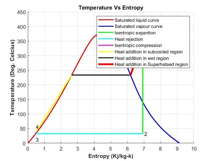
% Plotting T-S Diagram for Rankine Cycle
figure(1)
hold on
plot(sf,T,'color','b','linewidth',2,'color','r');
plot(sg,T,'color','b','linewidth',2,'color','b');
plot([s1 s2],[T1 T2], 'color', 'g','linewidth',2);
plot([s2 s3],[T2 T3], 'color', 'c', 'linewidth',2);
plot([s3 s4],[T3 T4], 'color', 'm', 'linewidth',2);
plot([s4 s5],[T4 T5], 'color', 'y', 'linewidth',2);
plot([s5 s6],[T5 T6], 'color', 'k', 'linewidth',2);

s_1 = linspace(s6,s1,1000);
for j = 1:length(s_1)
    Tc(j)= XSteam('T_ps',p1,s_1(j));
end

plot(s_1,Tc, 'color','r','linewidth',3.5)
legend('Saturated liquid curve','Saturated vapour curve','Isentropic expantion','Heat rejection','Isentropic compression','Heat addition in subcooled region','Heat addition in wet region','Heat addition in Superhetaed region')
grid on
text(s1+0.1, T1, '1')
text(s2+0.1, T2, '2')
text(s3, T3-20, '3')
text(s4, T4+20, '4')
title ('Temperature Vs Entropy','FontWeight','Bold')
xlabel ('Entropy (Kj/kg-k)', 'FontWeight','Bold')
ylabel ('Temeperature (Deg. Celcius)','FontWeight','Bold')

% Plotting H-S Diagram for Rankine Cycle
figure(2)
hold on
plot(sf,hf,'color','b','linewidth',2,'color','r');
plot(sg,hg ,'color','b','linewidth',2,'color','b');
plot ([s1 s2],[h1 h2],'color','g','linewidth' ,2);
plot ([s2 s3],[h2 h3],'color','c','linewidth' ,2);
plot ([s3 s4],[h3 h4],'color','m','linewidth',2);

hc = linspace(h4,h5,100);
for k = 1:length (hc)
         s_c(k) = XSteam ('s_ph' ,p1,hc (k));
end

plot(s_c ,hc ,'color','r ','linewidth',2)
plot ([s5 s6],[h5 h6],'color','r','linewidth',2)

for l = 1:length(s_1)
    h_c(l) = XSteam('h_ps',p1,s_1(l));
end

plot(s_1,h_c,'color','r','linewidth',3)
legend('Saturated liquid curve','Saturated vapour curve','Isentropic expantion','Heat rejection','Isentropic compression')
text(s1+0.1,h1,'1')
text(s2+0.1,h2,'2')
text(s3,h3-100,'3 ')
text(s4,h4+200,'4')
title('Enthalpy Vs Entropy','FontWeight','Bold')
xlabel('Entropy (Kj/kg-k)','FontWeight','Bold')
ylabel('Enthalpy (KJ /Kg)','FontWeight','Bold')
grid on


%  Displaying  Results  in  Command  window
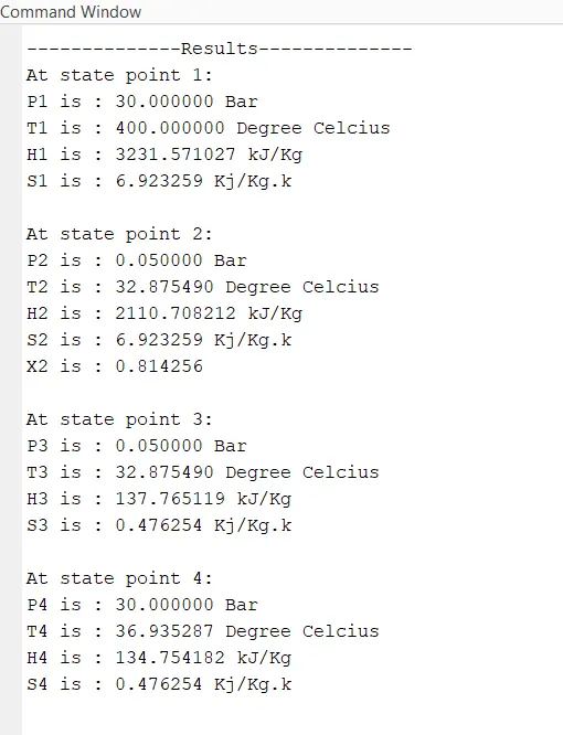
fprintf('\n--------------Results--------------\n')
fprintf('At state point 1:\n')
fprintf('P1 is : %f Bar\n',p1);
fprintf('T1 is : %f Degree Celcius\n',T1);
fprintf('H1 is : %f kJ/Kg\n',h1);
fprintf('S1 is : %f Kj/Kg.k\r\n',s1);

fprintf('At state point 2:\n')
fprintf('P2 is : %f Bar\n',p2);
fprintf('T2 is : %f Degree Celcius\n',T2);
fprintf('H2 is : %f kJ/Kg\n',h2);
fprintf('S2 is : %f Kj/Kg.k\n',s2);
fprintf('X2 is : %f \r\n',x2);

fprintf('At state point 3:\n')
fprintf('P3 is : %f Bar\n',p3);
fprintf('T3 is : %f Degree Celcius\n',T3);
fprintf('H3 is : %f kJ/Kg\n',h3);
fprintf('S3 is : %f Kj/Kg.k\r\n',s3);

fprintf('At state point 4:\n')
fprintf('P4 is : %f Bar\n',p4);
fprintf('T4 is : %f Degree Celcius\n',T4);
fprintf('H4 is : %f kJ/Kg\n',h4);
fprintf('S4 is : %f Kj/Kg.k\r\n',s4);

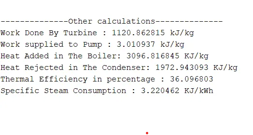
% Other calculations
fprintf('\n--------------Other calculations--------------\n')
fprintf ('Work Done By Turbine : %f kJ/kg\n',W_T)
fprintf ('Work supplied to Pump : %f kJ/kg\n',W_P)
fprintf ('Heat Added in The Boiler: %f KJ/kg\n' ,Q_in)
fprintf ('Heat Rejected in The Condenser: %f KJ/kg\n' ,Q_out)
fprintf ('Thermal Efficiency in percentage : %f \n',T_eff)
fprintf ('Specific Steam Consumption : %f KJ/kWh\r\n' ,Sp_S)
Output :
Plot between Temperature and Enthalpy
Plot between Enthalpy and Entropy
Conclusion
1. The efficiency of Rankine cycle is calculated and State points is obtained by using Matlab code.