Week -2
AIM :
- To make Simulink model of Doorbell using a solenoid block.
- To Use a thermistor to sense the temperature of a heater & turn on or turn off the fan as per specified conditions.
Reference Figure :
OBJECTIVE 1 :
To make a Simulink model of Doorbell using solenoid block with the following details:
- when the switch is closed the electromagnet receives electrical power from the battery and pulls the metal arm to hit the bell producing sound.
- Creating a situation where the switch is closed for 2 seconds and then released.
- Observing the physical movement of the plunger.
Explanation :
The following blocks are used for the making of this simulink model :
Solenoid :
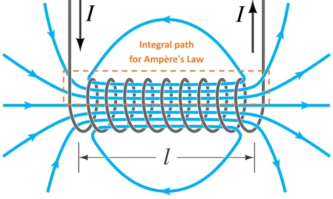
A solenoid is a very simple component, that includes a coil of wire that is covered around a core made out of a metal. When a current is applied to the solenoid, it has the effect of assembling a consistent magnetic field. Electricity changes to magnetism then it changes to electricity and, therefore, these two forces are united into one.
Magnetic Parameters :
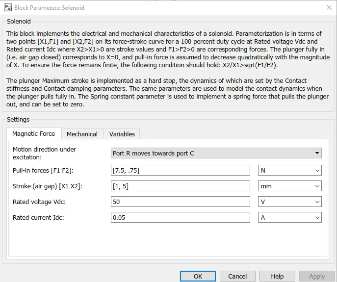
- The movement of the plunger is such that the port R moves towards port C when the circuit gets completed and the plunger moves.
- The force with which the plunger gets attracted to the solenoid is given by 7.5 N.
- The voltage and current values are given by 50 volts and 0.05 Ampere.
Mechanical parameters :
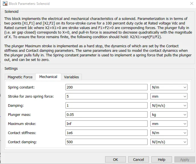
From the above figure we can get the value of the following parameters :
- Spring Constant is taken as 200 N/m.
- Damping coefficient = 1 n/(m/s).
- Plunger mass = 0.05 kg.
Variable Parameter :
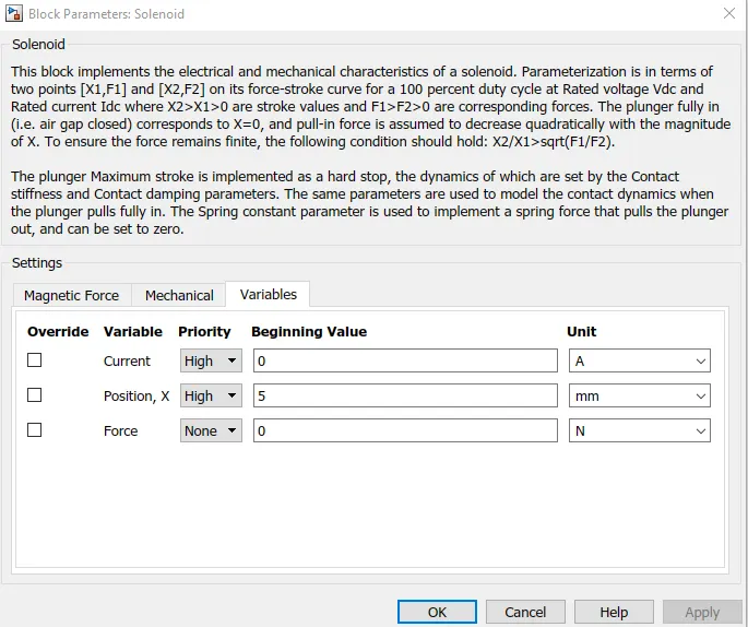
- The plunger gets to a maximum height of 5 mm after excitation.
Ideal Translational Motion:

The Ideal Translational Motion Sensor block represents a device that converts an across variable measured between two mechanical translational nodes into a control signal proportional to velocity or position. You can specify the initial position (offset) as a block parameter.
The sensor is ideal since it does not account for inertia, friction, delays, energy consumption, and so on.
Connections R and C are mechanical translational conserving ports that connect the block to the nodes whose motion is being monitored. Connections V and P are physical signal output ports for velocity and position, respectively.
The block positive direction is from port R to port C. This means that the velocity is measured as v = vR – vC, where vR, vC are the absolute velocities at ports R and C, respectively
Mechanical Translational Reference :

The Mechanical Translational Reference block represents a reference point, or frame, for all mechanical translational ports. All translational ports that are rigidly clamped to the frame (ground) must be connected to a Mechanical Translational Reference block.
Switch :

The Switch block models a switch controlled by an external physical signal. If the external physical signal PS is greater than the value specified in the threshold parameter, then the switch is closed, otherwise the switch is open.
Solver :
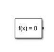
Each physical network represented by a connected Simscape™ block diagram requires solver settings information for simulation. The Solver Configuration block specifies the solver parameters that your model needs before you can begin simulation.
Each topologically distinct Simscape block diagram requires exactly one Solver Configuration block to be connected to it.
Pulse Generator :
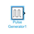
The Pulse Generator block generates square wave pulses at regular intervals. The block waveform parameters, Amplitude, Pulse Width, Period, and Phase delay, determine the shape of the output waveform. The following diagram shows how each parameter affects the waveform.
Battery :
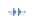
The Battery block represents a simple battery model. The block has four modeling variants, accessible by right-clicking the block in your block diagram and then selecting the appropriate option from the context menu, under Simscape > Block choices.
Electrical Reference :
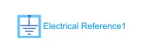
The Electrical Reference block represents an electrical ground. Electrical conserving ports of all the blocks that are directly connected to ground must be connected to an Electrical Reference block.
Simulink Model For Door Bell :
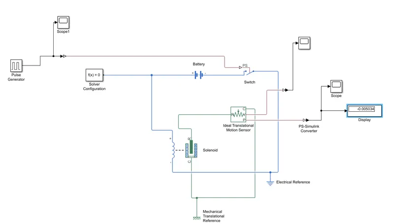
- First to make a door bell circuit : A switch is taken, which is connected to the battery block, when current passes through the switch the circuit gets completed.
- The switch is connected to the electrical reference, the electrical reference represents a ground connection.
- A solenoid block is also taken which is connected to the battery, the positive terminal of the solenoid is connected to the negative terminal of the battery, once the circuit is completed solenoid gets activated and the plunger starts to move.
- Port R anc C are two variables in the solenoid which determines the position and fixed point of the plunger.
- Connections R and C are mechanical translational conserving ports, port R of solenoid is connected to the port R of motion sensor, which senses the position of the punger in the solenoid and gives the output.
- The port C of the motion sensor is connected to the port C of solenoid which is a fixed port.
- Connections V and P are physical signal output ports for velocity and position.
- Now this circuit is connected to mechanical translational reference which represents a reference point or frame for all mechanical translational port.
- The port P is connected to the PS - Simulink Converter converts physical blocks of the simulink into simulink output signal.
- Further the port P is connected to Scope block which generates a output graph, along with it a display block is provided which gives us the output value.
Pulse Generator :
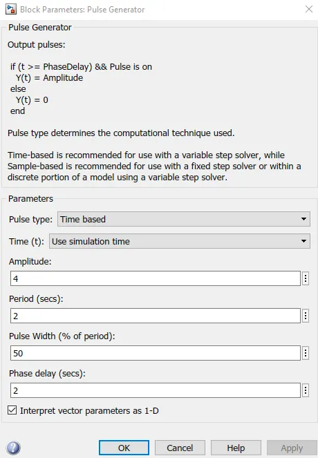
- Here, we fixed the pulse generator signal to a specified parameters.
- The amplitude is given a value of 4.
- The period of the pulse is taken as 4seconds..
- The pulse width is 50
- And the phase delay is given a gap of 2 seconds.
- Considering, the specified parameters, with a amplitude of 4 the signal starts from 0 and goes to a peak value of 4.
- Because of phase delay of 2 seconds the maximum value of signal is 1 and after 2 seconds again comes back to 0 and repeats the same procedure.
- The period of the signal is 4, hence it completes one pattern in 4 seconds and then it repeats the same again.
- The width of signal is 50% of pulse width.
Input Signal :
TIME VS AMPLITUDE :
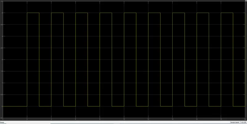
- A pulse generator is used to generate a signal the Pulse Generator block generates square wave pulses at regular intervals
- The above plot gives us a plot of Time vs Amplitude.
- It starts at 0, and goes to a peak value of 4 as athe amplitude is set as 4.
- Again the graph falls down a to zero.
- And after 2 seconds the signal starts again, as the period is for 2 seconds.
Results :
TIME VS VELOCITY :
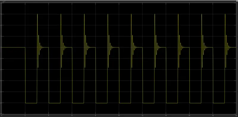
- This plot shows the graph with respect to the amplitude .
- As the amplitude is 1, once it reaches the maximum position the bell rings and again the plunger falls back to its original position.
- Every 2 seconds the bell rings and gives a deviation.
TIME VS POSITION :
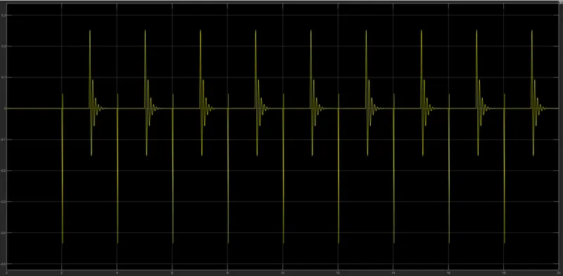
- This graph shows the position of plunger in the solenoid with respect to the two variables R and C.
- We can also observe that whenever there is a change in the position of the plunger, there is a formation of waves.
- This is due to recoil of spring.
- As the period is given 2 the signal has a delay of 2 seconds.
- Hence it rings every 2 seconds.
- When the signal reaches a maximum value of 1 the plunger moves and bell rings and again it comes back to its fixed position.
OBJECTIVE 2 :
Using a thermistor to sense the temperature of a heater & turn on or turn off the fan as per below conditions:
Temperature source :
- 20 °C from 0 - 10 seconds,
- 27 °C from 10 - 30 seconds,
- 23 °C from 30 - 50 seconds.
Fan conditions :
ON if the temperature > 25 °C,
Else, OFF.
Explanation :
The blocks used during the simulink model are as follows :
Thermistor :
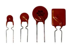
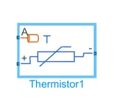
A thermistor is a resistance thermometer, or a resistor whose resistance is dependent on temperature. The term is a combination of “thermal” and “resistor”. It is made of metallic oxides, pressed into a bead, disk, or cylindrical shape and then encapsulated with an impermeable material such as epoxy or glass.
There are two types of thermistors: Negative Temperature Coefficient (NTC) and Positive Temperature Coefficient (PTC). With an NTC thermistor, when the temperature increases, resistance decreases. Conversely, when temperature decreases, resistance increases. This type of thermistor is used the most.
A PTC thermistor works a little differently. When temperature increases, the resistance increases, and when temperature decreases, resistance decreases. This type of thermistor is generally used as a fuse.
Typically, a thermistor achieves high precision within a limited temperature range of about 50ºC around the target temperature. This range is dependent on the base resistance.
Voltage Sensor :
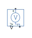
The Voltage Sensor block represents an ideal voltage sensor, that is, a device that converts voltage measured between two points of an electrical circuit into a physical signal proportional to the voltage.
Connections + and – are electrical conserving ports through which the sensor is connected to the circuit. Connection V is a physical signal port that outputs the measurement result.
Resistor :
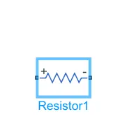
The Resistor block models a linear resistor, described with the following equation:
V=I·R
where,
V = Voltage.
I= Current.
R = Resistance.
Connections + and – are conserving electrical ports corresponding to the positive and negative terminals of the resistor, respectively. By convention, the voltage across the resistor is given by V(+) – V(–), and the sign of the current is positive when flowing through the device from the positive to the negative terminal. This convention ensures that the power absorbed by a resistor is always positive.
Battery :
Controlled Temperature Source :
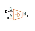
- The Controlled Temperature Source block represents an ideal source of thermal energy that is powerful enough to maintain specified temperature difference across the source regardless of the heat flow consumed by the system.
- Connections A and B are thermal conserving ports corresponding to the source inlet and outlet, respectively. Port S is a physical signal port, through which the control signal that drives the source is applied.
- We can use the entire variety of Simulink signal sources to generate the desired heat flow variation profile. The temperature differential across the source is directly proportional to the signal at the control port S.
- The block positive direction is from port A to port B. This means that the temperature differential is determined as TB – TA, where TB and TA are the temperatures at source ports.
Signal Builder :
Switch :
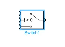
The Switch block passes through the first input or the third input signal based on the value of the second input. The first and third inputs are data input. The second input is a control input. Specify the condition under which the block passes the first input by using the Criteria for passing first input and Threshold parameters.
.
Constant :
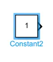
The Constant block generates a real or complex constant value signal. Use this block to provide a constant signal input. The block generates scalar, vector, or matrix output, depending on :
- The dimensionality of the Constant value parameter.
- The setting of the Interpret vector parameters as 1-D parameter.
Simulink Model For Thermistor :
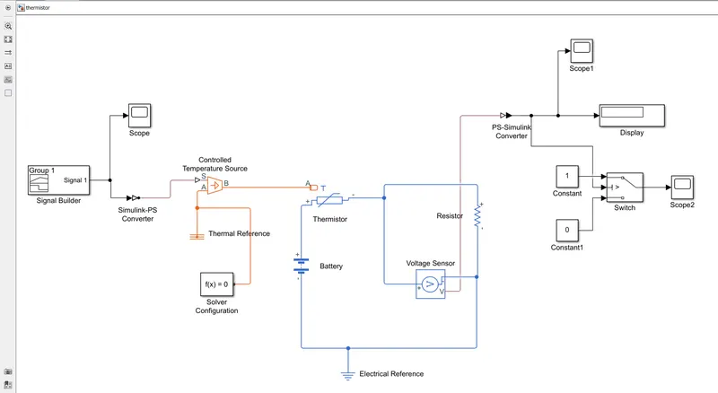
Explanation :
- First to run the simulink model the basic blocks that are required are Thermistor, a controlled temperature source, voltage sensor, resistor, Signal Builder and a switch.
- The positive terminal of the thermistor block is connected to the positive terminal of the battery block.
- And the negative terminal of the thermistor block is connected to the positive terminal of the resistor block.
- The voltage sensor is used to measure the voltage, the voltage sensor and the resistor is connected in parallel as the voltage must be in a parallel connection to the resistance.
- Now the electrical connection is given a electrical reference which is generally given of earthing.
- A controlled temperature source block is taken , the B port is connected to the port A of thermistor, the port A is connected to the thermal reference, and S port is taking input from the signal builder. There is a temperature difference between the two ports hence the port B has greater temperature difference than port A.
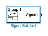
- The signal builder is connected to the PS -Simulink converter to convert the block into readable input and scope is also attached to get a input graph.
- The input from voltage is taken to the PS-Simulink converter, to convert the block into a physical signal, and a scope is also attached to get a graph.
- A switch is attached to regulate the voltage source.
- The two constant block is connected to the switch block, the top part of the switch is connected to the constant block 1 and the bottom part of the switch is connected to the constant block 0.
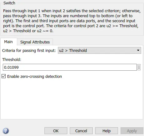
- The middle port of the switch is connected to the voltage sensor, the switch is given a threshold value.
- Whenever the input goes above the threshold value the constant block 1 will operate and switch will allow the current to flow through.
- Whenever the input goes below the threshold value the constant block 0 will operate and switch will stop the flow of current.
- The threshold value of the switch is given as 0.01099.
Signal :
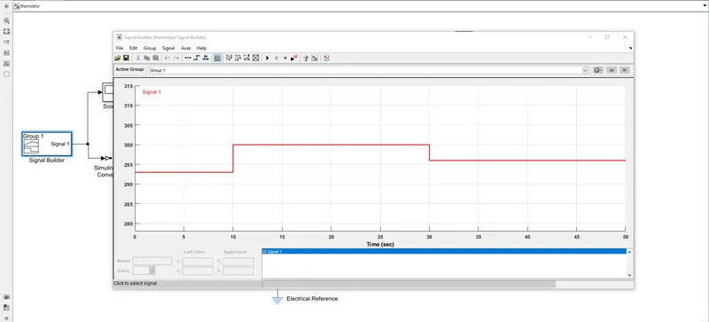
The above figure gives us a input signal :
- The x-axis of the plot represents time which has a range of 50 seconds.
- The y-axis of the plot represents the temperature range which ranges from (293 -300) kelvin.
- For first 0 -10 seconds it has a value of 293 kelvin.
- Then from 10 - 30 seconds it has a value of 300 kelvin.
- And from 30 - 50 seconds it has a value of 296 kelvin.
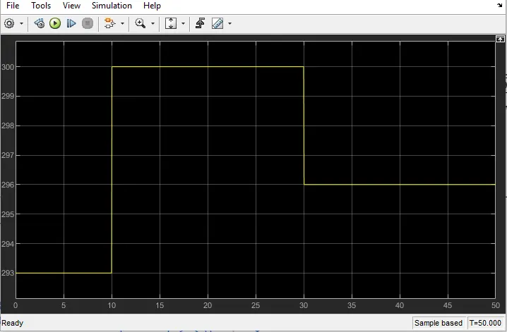
The above signal as seen through the scope gives us a graph with the same specific dimensions of time vs temperature.
RESULT :
Temperature vs Voltage :
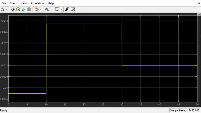
- The above plot gives a graph between temperature vs voltage.
- From the graph it is evident that from (0-10) seconds at 293 kelvin the voltage ranges from 0.0095 - 0.01 volts.
- From (10 - 30) seconds at 300 kelvin the voltage range is from 0.0125 - 0.013.
- From (30 - 50) seconds at 296 kelvin the voltage is nearly 0.011.
ON VS OFF
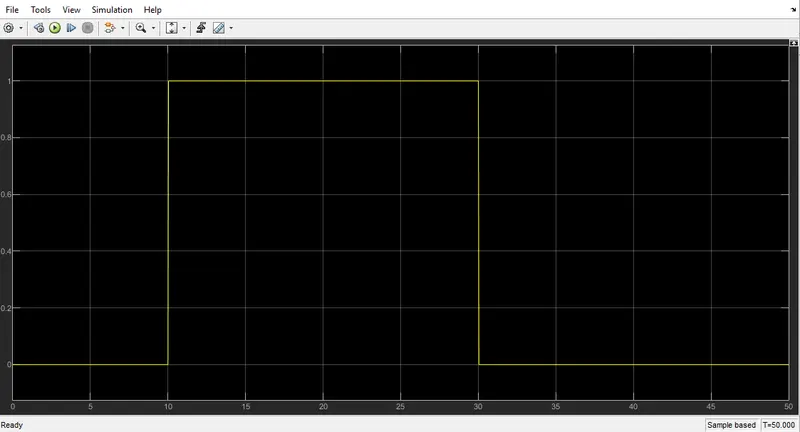
- From the above plot we can clearly understand that
- 0 represents the ON Condition.
- 1 represents the OFF condition.
- The fan is ON if the temperature above 25 °C.
- And the fan if off below it.