Week -2
AIM:
1.To Make a Simulink model of Doorbell using solenoid block 1.
2. To use a thermistor to sense the temperature of a heater & turn on or turn off the fan
OBJECTIVE:
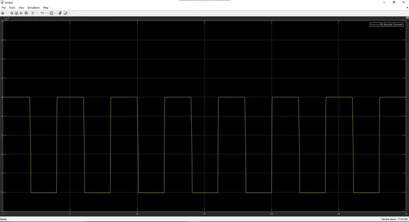
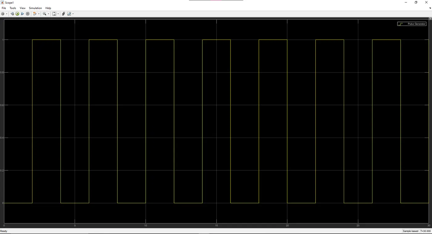
1. To Create a situation where the switch is closed for 2 seconds and then released, Observe the physical movement of the plunger.
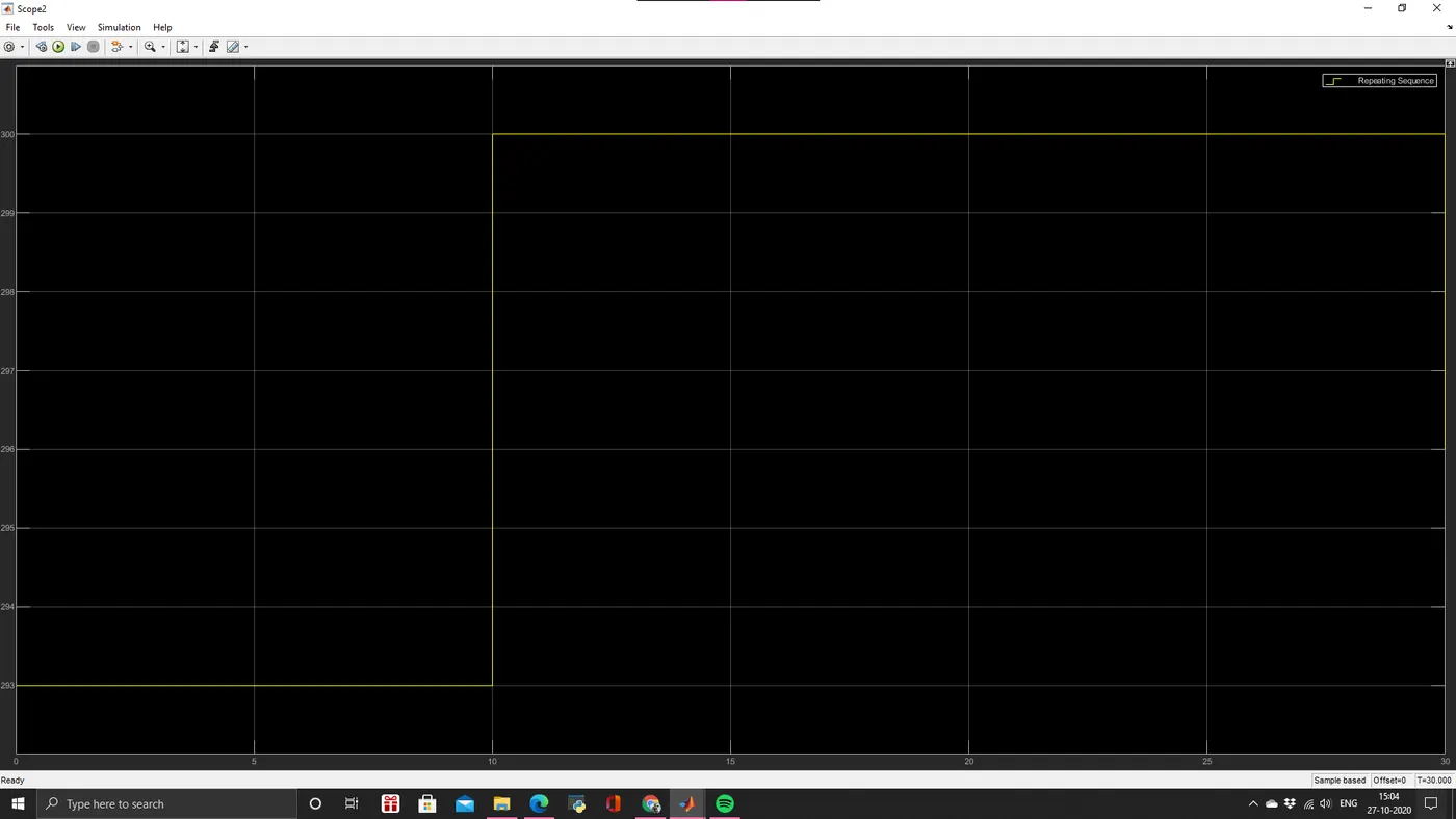
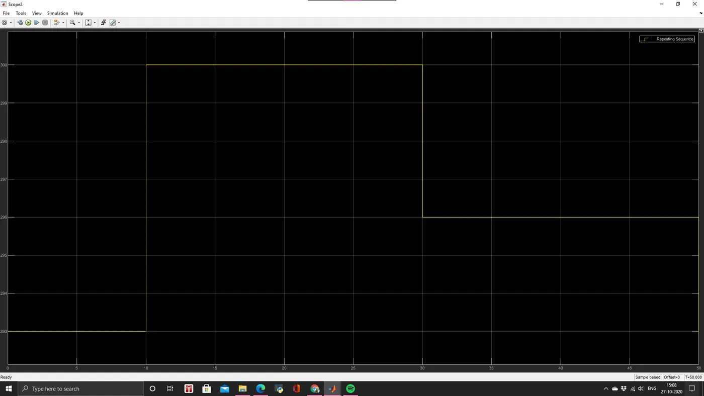
2 To sense the temperature of a heater by using some condition are given below Temperature source 20 C from O to 10 seconds, 27 C from 10 to 30 seconds, 23 C from 30 to 50 seconds
Fan conditions: ON if the temperature above 25 C. OFF
THEORY:
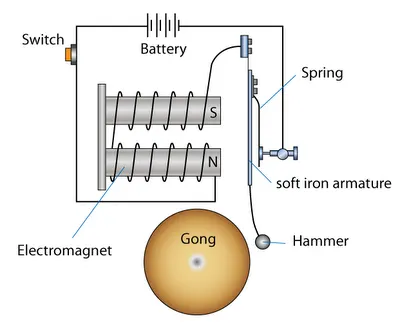
1. DOOR BELL
When you press a doorbell button you complete an electrical circuit that allows household electricity to flow through the doorbeils internal electromagnet. The magnetic field generated by the electromagnet is then used to power a mechanism that creates the doorbell sound doorbells are low voltage device.
SIMULINK MODEL:
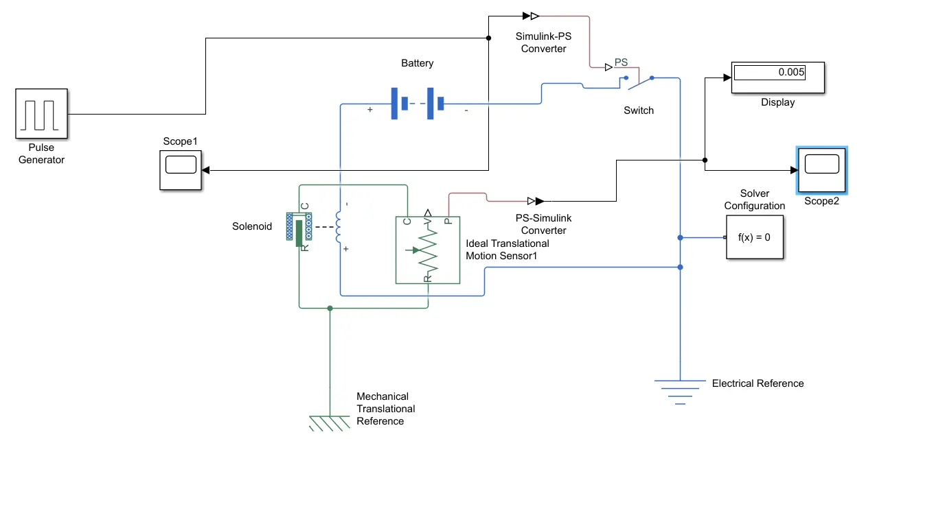
BLOCKS USED:-
1.Pulse Generator - to generate time signals to control the switch operation
2. Scope - For viewing the graph of the signals
3. Simulink PS- To convert Simulink environment to Real Time environment
4.Switch - An ON/OFF control switch (Single Pole Single Throw Switch)
5. Battery-Power source for the bell to ring
4. Electrical Mechanical References - Denoting that all the electrical and mechanical biocon are grounded properly
6. Solenoid block - To generate magnetic field to attract the hammer to ring the bell
7. PS Simulink - To convert Real Time environment to Simulink environment
FLOW PROCESS :-
1.In the pulse generator signals are generated for every 2 sec to control vie switch to ring the bell
2. The generated signals are plotted and then converted to real time environment Then according to the signal the switch acts to control the flow of the current to the solenoid
3. When The current is possed to the salenoid it generates magnetic field to attract the iron armature
4. From the solenoid the Motion is sensed using ideal Mation Sensor then the signals are converted to Simulink phase to record the motion of the hammet
RESULTS:
GENERATED PLOT:
SOLENOID:
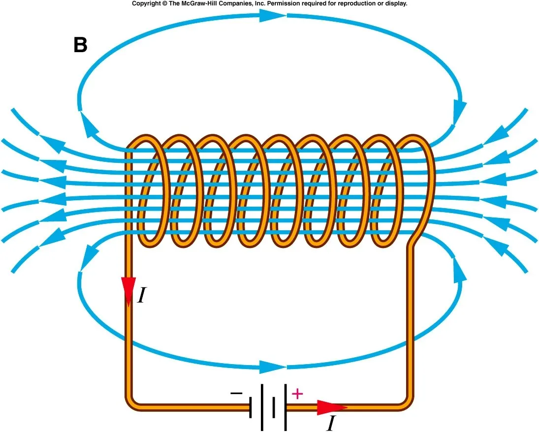
A solenoid is a three dimensional structure of wire. When this wire is wrapped around a metallic block in a coil and electricity is passed through it it has some special magnetic properties. Electromagnetic induction makes it an electromagnet that can be switched on or off. The side in which the current appears to be passing clockwise, is the South Pole, and the side in which the current seems to be passing anticlockwise is the Northern Pole. The solenoid works just like a bar magnet therefore has many uses.
WORKING PRINCIPLE OF DOORBELL BY USING SOLENOID:
- The switch is pressed and current flows through the circuit.
- The electromagnet is powered and generates a magnetic field that attracts the iron strip towards it.
- The striker strikes the gong belt).
- When the striking arm strikes the gong, the contact is broken and current stops flowing through the circuit This causes the electromagnet to lose its magnetic field
- The connected spring arm returns the striker to its original rest position.
- The contact is restored and current flows through the circuit (provided the main switch is still pressed) The process is repeated from the beginning
SIMULINK MODEL:
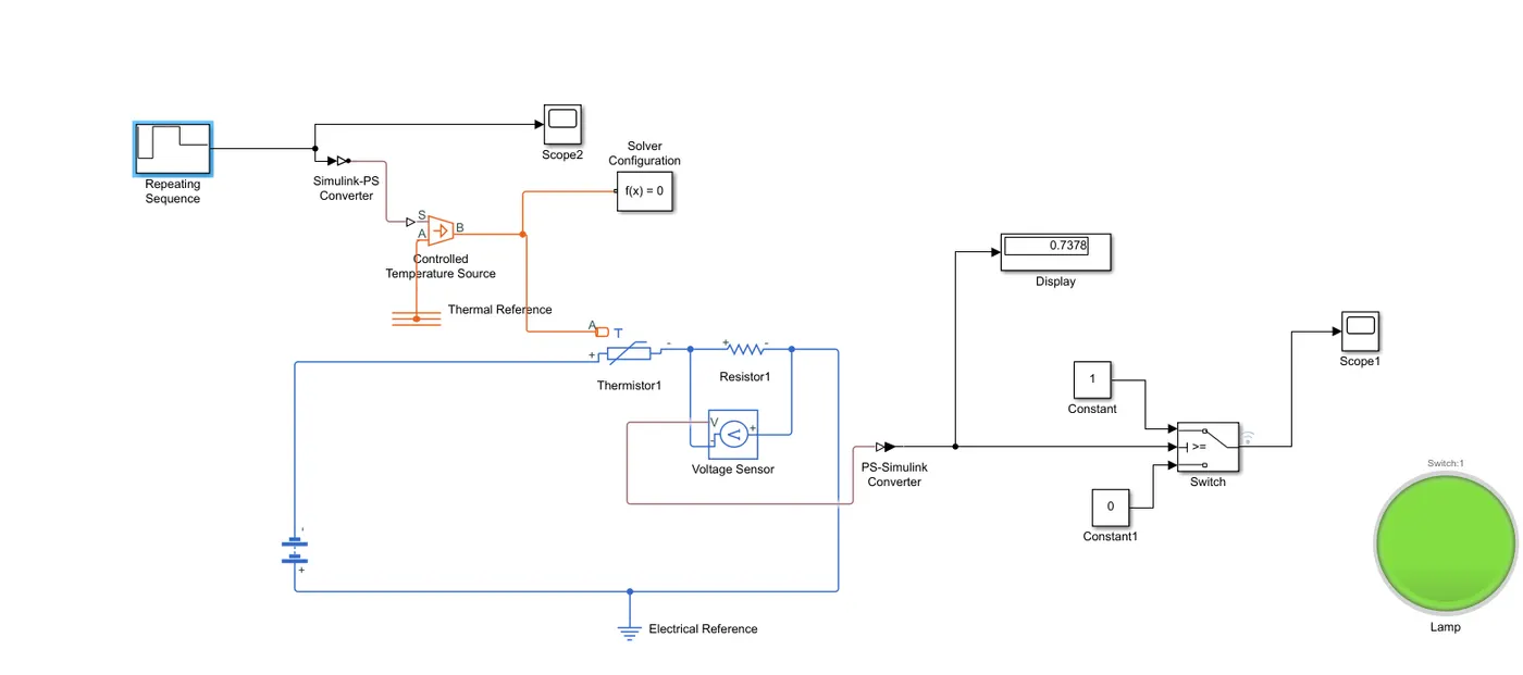
BLOCKS USED -
1.Repeating Sequence - Generate arbitrarily shaped periodic signal
2. Scope - For viewing the graph of the signals
3. Simulink-PS - To convert Simulink environment to Real Time environment
4. Thermistor - To sense the temperature for producing resistance V. Battery - Power source
5. Simulink-PS - To convert Simulink environment to Real Time environment
6. Voltage Sensor - To sense the voltage across the circuit
7. PS Simulink - To convert Real Time environment to Simulink environment
8. (Threshold Controlled) Switch - To control the voltage output at particular threshold value
9. Control Voltage Source - To separate the voltage info (8-) ions.
10. DC Motor - To run at controlled voltage
11. Electrical - Denoting that all the electrical grounded properly
12. Display - To view the threshold value of the voltage
FLOW PROCESS:-
The signal builder generates the time interval with various temperature as a source of heater
Conditions of Heat Source
T = 20 Degree Celcius for (0-10)
T= 27 Degree Celcius for (10-30 s)
T = 23 Degree Celcius for (30-50 s)
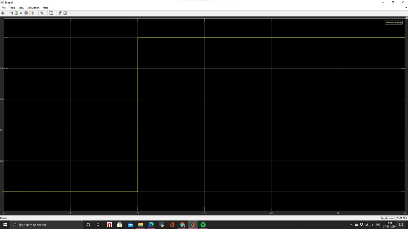
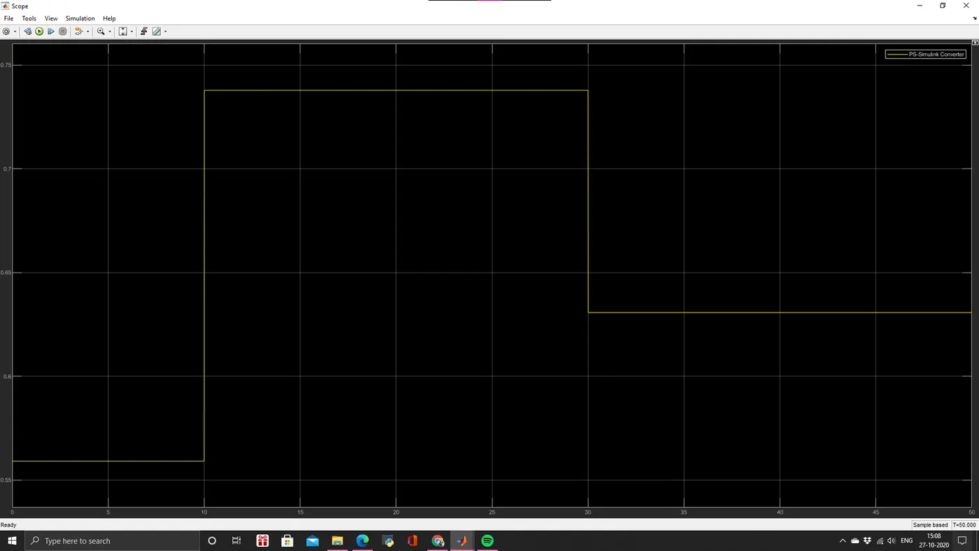
Condition for FAN
T= 25 Degree Celcius > ON
T= 25 Degree Celcius<OFF
OUTPUT:
DURING ON:
GRAPHS:
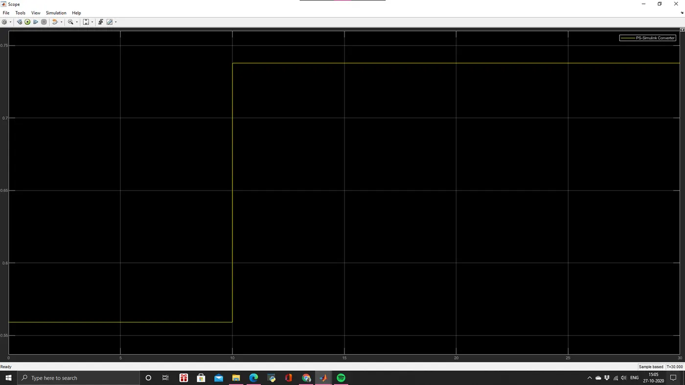 DURING OFF GRAPH:-
REFERENCE:
1. https://in.mathworks.com/help/simulink/index.html?s_tid=CRUX_lftnav
2. SKILL-LYNC Teacher.