Week -2
AIM:
1) Make a Simulink model of Doorbell using solenoid block with the following details:
In the above arrangement, when the switch is closed the electromagnet receives electrical power from the battery and pulls the metal arm to hit the bell producing sound.
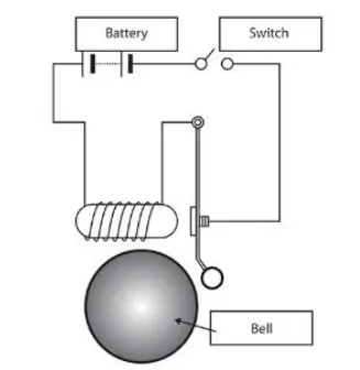
Create a situation where the switch is closed for 2 seconds and then released. Observe the physical movement of the plunger.
2) Use a thermistor to sense the temperature of a heater & turn on or turn off the fan as per the below conditions:
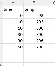
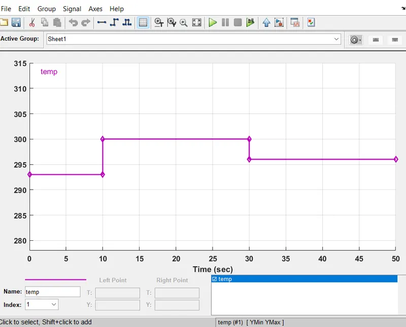
Temperature source: 20 °C from 0 to 10 seconds, 27 °C from 10 to 30 seconds, 23 °C from 30 to 50 seconds
Fan conditions: ON if the temperature above 25 °C, OFF otherwise.
ANSWER:
Part 1: Make a Simulink model of Doorbell using solenoid block.
Theory:
Doorbell working mechanisim - The most important part of a door bell is its magnetic motor. The magnetic motor constitutes a conventional electromagnet. We know that an electromagnet is an arrangement in which a coil of wire is wrapped around magnetic material which produces magnetic field when electricity is passed through the coil. The greater the coiling of the wire, the higher the amplification of magnetic field. This magnetic field produces a substantial effect on any magnetic substance when brought in the vicinity of its magnetic field. This means that when an iron object is placed in this magnetic field, it will be attracted towards the magnetic field due to polar orientation generated by the electromagnetism.
Solenoid - A solenoid is a type of electromagnet formed by a helical coil of wire whose length is substantially greater than its diameter, which generates a controlled magnetic field. The coil can produce a uniform magnetic field in a volume of space when an electric current is passed through it.
Simulink Model for Doorbell:
Blocks used in the Model:
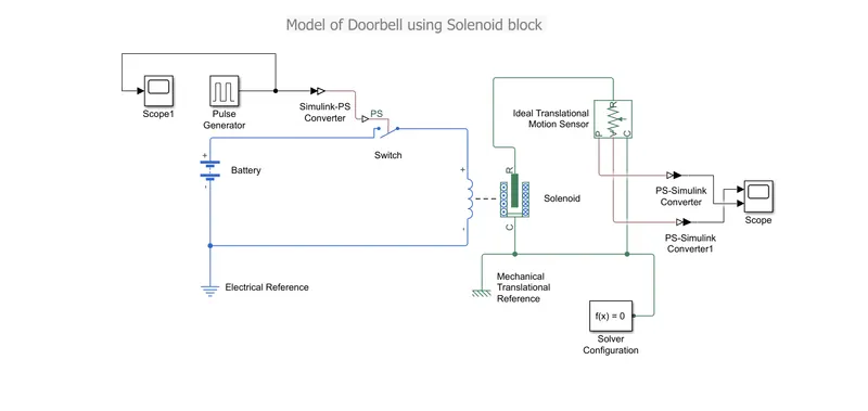
- Pulse generator - This block generates square wave pulses at regular intervals. The block waveform parameters, amplitude, pilse width, period and phase delay determine the the shape of the output waveform.
- Scope - Displays signals generated during the simulation.
- Simulink-PS converter - Converts simulink signal to the physical signal.
- Switch - Switch controlled by external physical signal.
- Battery - It represents the simple battery model.
- Solenoid - It represents the electrical charactersitics and generated force of solenoid.
- PS-Simulink converter - Converts physical signal to simulink signal.
- Solver Configuration - It specifies the solver parameters that your model needs before the simulation.
- Electrical Reference - This block represent the electrical ground. Electrical conserving ports of all the blocks that are directly connected to the ground must be connected to an electrical reference block. Model with electrical elements must contain atleast one electrical reference block.
- Mechanical Translational Reference - This block represents a reference point or frame for all mechanical translational ports.
- Ideal Translational Motion Sensor - This represents a device that converts an across variable measured between two mechanical translational nodes into a control signal proportional to velocity or position. You can specify the initial position (offset) as a block parameter. The sensor is ideal since it does not account for inertia, friction, delays, energy consumption and so on.
EXPLANATION:
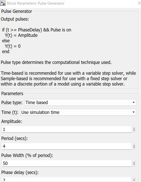
- The pulse generator is used to give the signal input where, Amplitude = 1, Period = 4sec, Pulse width = 50% and phase delay = 2sec.
- Simulink-PS converter is used to convert the signal to physical form and then it is send to the switch of the electrical circuit.
- The electrical circuit consists of a solenoid, a battery and switch. one end of the solenoid is connected to the battery and its other end is connected to the switch. An electrical reference is provided in the electrical circuit.
- The mechanical part of the solenoid is connected to an ideal translational motion sensor and mechanical translational reference.
- The P- port of the sensor makes a connection with the PS-simulink converter to provide the output in signal form, further scope is connected to display the output signal.
- A solver configuration is attached to an electrical circuit to solve all parameters before the beginning of the simulation.

OUTPUT:
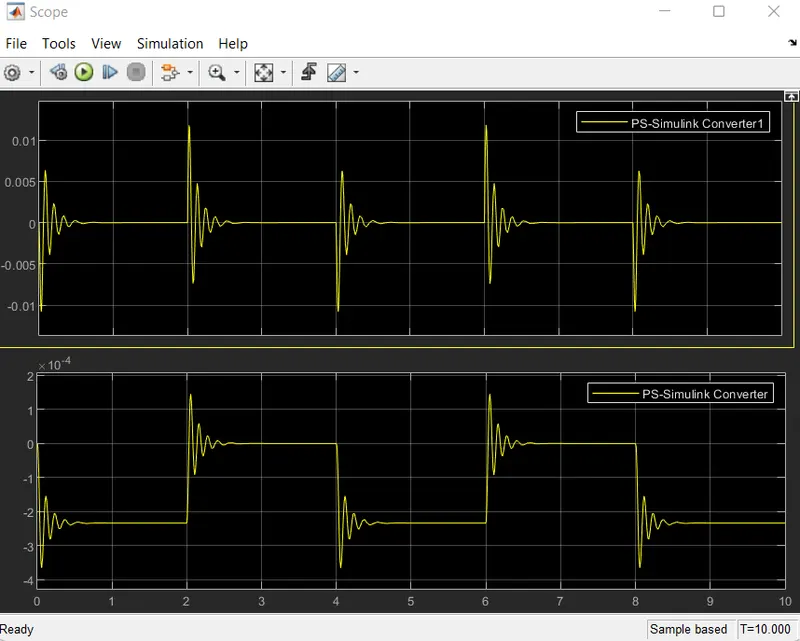
Here we can see that the switch is closed for 2 seconds and opened. Amplitude =0 means switch is closed and we can notice that the plunger strikes the ball after every 2 seconds.
PART 2: Use a thermistor to sense the temperature of a heater & turn on or turn off the fan as per the conditions.
Theory:
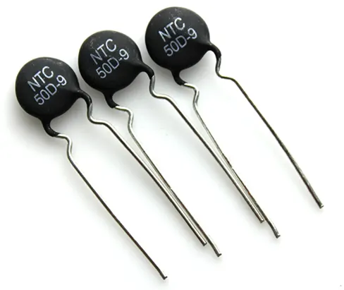
A thermistor is defined as a type of resistor whose resistance varies with temperature changes. Thermistors are particularly sensitive to temperature changes.
Thermistors act as a passive component in a circuit, they are accurate, cheap and robust way to measure temperature. While they do not work well in extremely hot or cold temperatures, but they are the sensor of choice for many different applications.
Simulink model using thermistor:
Blocks used in Model:
1). Thermistor
The Thermistor block represents an NTC thermistor using the B-parameter equation. The resistance at temperature T is
R=R0eB(1/T−1/T0)
where:
-
R0 is the nominal resistance at the reference temperature T0.
-
B is the characteristic temperature constant.
The following equation describes the thermal behavior of the block:
Q=KdtcdTdt
where:
-
Q is the net heat flow into port A.
-
Kd is the Dissipation factor parameter value.
-
tc is the Thermal time constant parameter value.
-
dT/dt is the rate of change of the temperature.
2). Signal builder
- The Signal Builder block allows you to create interchangeable groups of piecewise linear signal sources and use them in a model. You can quickly switch the signal groups into and out of a model to facilitate testing. In the Signal Builder window, create signals and define the output waveforms.
3). Switch
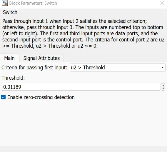
- The Switch block passes through the first input or the third input signal based on the value of the second input. The first and third inputs are data input. The second input is a control input. Specify the condition under which the block passes the first input by using the Criteria for passing first input and Threshold parameters.
4). Battery
- The Battery block represents a simple battery model. If you select
Infinitefor the Battery charge capacity parameter, the block models the battery as a series resistor and a constant voltage source. If you selectFinitefor the Battery charge capacity parameter, the block models the battery as a series resistor and a charge-dependent voltage source defined by
V=Vnom x SOC/(1−β(1−SOC))
Where
Soc - State of charge,
Vnom - Nominal Voltage,
β - Constant that is calculated to satisfy user defined data points(AH1,V1).
5). Voltage Sensor:
- The Voltage Sensor block represents an ideal voltage sensor, that is, a device that converts voltage measured between two points of an electrical circuit into a physical signal proportional to the voltage.
- Connections + and - are conserving electrical ports through which the sensor is connected to the circuit. Connection V is a physical signal port the outputs voltage value.
6). Resistor:
The Resistor block models a linear resistor, described with the following equation:
V=I·R
where:
-
V is voltage.
-
I is current.
-
R is resistance.
Connections + and – are conserving electrical ports corresponding to the positive and negative terminals of the resistor, respectively. By convention, the voltage across the resistor is given by V(+) – V(–), and the sign of the current is positive when flowing through the device from the positive to the negative terminal. This convention ensures that the power absorbed by a resistor is always positive.
7). Controlled temperature source
- The Controlled Temperature Source block represents an ideal source of thermal energy that is powerful enough to maintain specified temperature difference across the source regardless of the heat flow consumed by the system.
- Connections A and B are thermal conserving ports corresponding to the source inlet and outlet, respectively. Port S is a physical signal port, through which the control signal that drives the source is applied. You can use the entire variety of Simulink® signal sources to generate the desired heat flow variation profile. The temperature differential across the source is directly proportional to the signal at the control port S.
- The block positive direction is from port A to port B. This means that the temperature differential is determined as TB – TA, where TB and TA are the temperatures at source ports.
8). Thermal Reference
- This block represents a reference point in a thermal network where the temperature is equal to absolute zero.
9). Electrical Reference
- This block represent the electrical ground. Electrical conserving ports of all the blocks that are directly connected to the ground must be connected to an electrical reference block. Model with electrical elements must contain atleast one electrical reference block.
10). Constant Block
-
The Constant block generates a real or complex constant value signal. Use this block to provide a constant signal input. The block generates scalar, vector, or matrix output, depending on:
-
The dimensionality of the Constant value parameter
-
The setting of the Interpret vector parameters as 1-D parameter
The output of the block has the same dimensions and elements as the Constant value parameter. If you specify for this parameter a vector that you want the block to interpret as a vector, select the Interpret vector parameters as 1-D check box. Otherwise, if you specify a vector for the Constant value parameter, the block treats that vector as a matrix.
-
11). Scope
- Displays signal generated during simulation.
12). Solver Configuration
- Define solver settings to use for simulation
13). Simulink-PS converter
- Converts simulink signal to physical signal
14). PS-Simulink converter
- Converts physical signal to simulink signal
EXPLANATION:
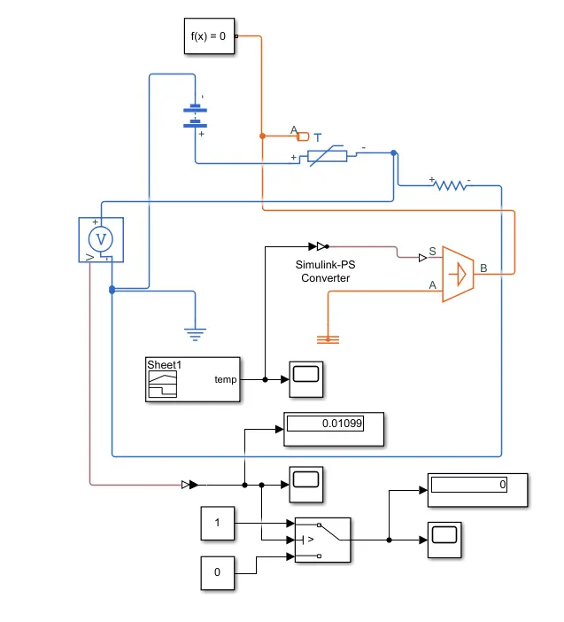
- At first the signal is created in Signal builder and further passes to Simulink-PS converter to convert the input signal into the physical signal.
- This physical signal is connected to a block Controlled Temperature source. This block is connected to the thermistor and a Thermal reference block.
- The thermistor is a part of an electric circuit where a battery, a voltage sensor, a resistor connected parallel to the voltage sensor, an electrical reference are connected to make a complete circuit. A solver configuration is connected to the electrical circuit to solve all parameters before the beinning of the simulation.
- The voltage sensor senses the temperature in the form of voltage and sends the data to its port in V
- From this port we get our output and send it to two different PS-Simulink convereter.
- From converter -1, the signal is sent to the threshold switch. In the switch, the threshold limit is set to the defined value. If the temperature is below the threshold limit, then it will give 0 as output which means Switch off. The input signal is generated with the help of a signal builder
- The switch is connected to the scope where we can see the output plot.
- From converter 2 it converts physical signal to the simulink signal and sends the voltage data to the displaty. This display gives the threshold value which is set in the switch.
OUTPUT:
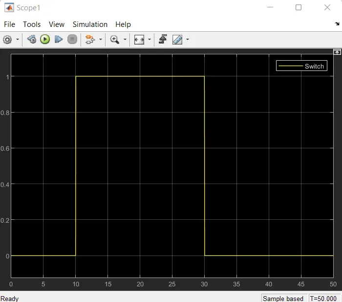
It can be seen that the value of the signal is 0 from 0 to 10 sec because the temperature value is below 25 deg C which leads to switch off the fan, then the signal is 1 from 10 to 30 sec because the temperature is above 25 deg C so the Switch turns on the fan, again the temperature drops switch is turned off by giving the signal 0.