Project
Aim:
To study and prepare technical report for system-level simulation of BAJA ATV.
OBJECTIVE:
- Study of BAJA ATV model without dashboard
- Study of BAJA ATV model with dashboard
- Study of BAJA ATV model using lookup table without dashboard
- Study of BAJA ATV model using lookup table with dashboard
INTRODUCTION:
All-Terrain Vehicle:
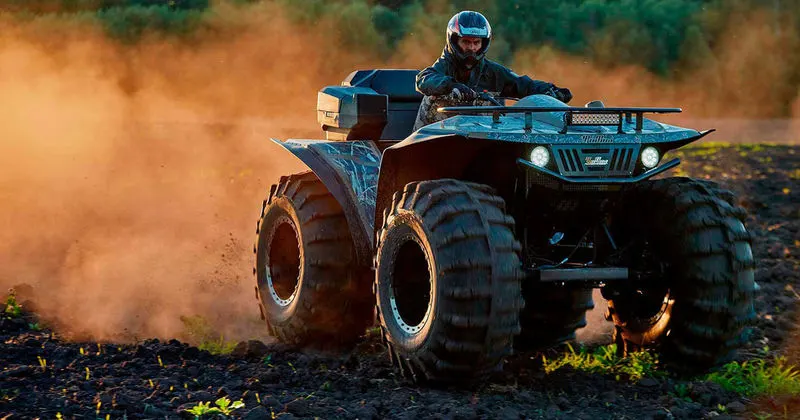
An all-terrain vehicle (ATV), also known as a light utility vehicle (LUV),a quad bike, or simply a quad, as defined by the American National Standards Institute (ANSI), is a vehicle that travels on low-pressure tires, with a seat that is straddled by the operator, along with handlebars for steering control. As the name implies, it is designed to handle a wider variety of terrain than most other vehicles.
Continious Variable Transmission:
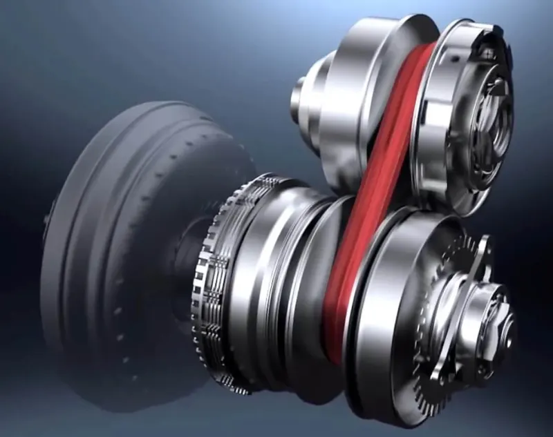
A continuously variable transmission, or CVT, is a type of automatic transmission that provides more useable power, better fuel economy and a smoother driving experience than a traditional automatic transmission. The CVT is a system that makes it possible to vary stepless the transmission ratio without interruption of the torque flow. Therefore an infinite number of ratios (between a minimum and maximum value) are possible. It is an automatic, single speed, and gearless transmission that can shift through an infinite number of gear ratios. This ability to seamlessly shift through these different gears provides a number of benefits including extremely smooth shifts and exceptional fuel economy. A CVT draws top engine power from a small engine, which gives drivers quicker acceleration than standard automatic transmissions. Because of their greater ability to control the engine speed range, CVTs produce fewer emissions. CVTs are also lighter weight than traditional automatic transmissions.
Simulink model:
Blocks Used in the model:
- Signal Builder - To input the Brake, Throttle and CVT Ratio.
- Simulink to PS Converter - To convert the Simulink signal to Simscape environment.
- Solver Configuration - To specify the solver parameters before starting the simulation.
- Mechanical Reference - To make sure all the components are clamped to the ground.
- Generic Engine - To run the engine with speed and torque values as input.
- PS to Simulink Converter - To convert Simscape signal to Simulink environment.
- Scope - To view the graph of the parameters for better understanding.
- Display - To view the calculated engine power.
- Inertia - To represent the solid inertia.
- Rotational Motion Sensor - To sense the rotational motion from the engine and give output as rpm.
- Variable Gear Ratio - To vary the speed according to the gear ratios.
- PS Terminator - Terminator for unconnected physical signal outputs.
- Double Shoe Brake - To apply brake to the vehicle when needed.
- PS Constant - Generate constant physical signal.
- Tire - For transportation of the vehicle.
- Rotational Free End - For mechanical component (Tire)
- Vehicle Body-To represent the BAJA ATV model body
- Custom Measure Gauge - To measure the brake and throttle input
- Knob - To increase, decrease and vice-versa of throttle and brake inputs
- Lookup Table - To insert the CVT values from the workspace
- Simple Gear - To reduce the speed of the engine with pre-defined gear ratio
- Step - To increase or decrease an input value for a defined time interval
STUDY 1- Study of BAJA ATV model without dashboard:
Simulink Model:
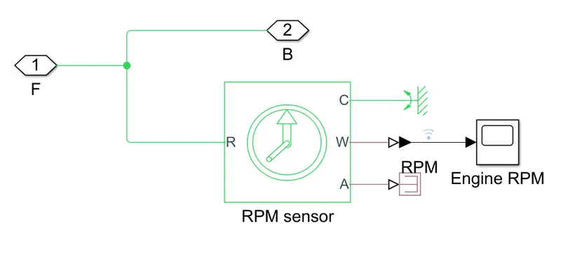
Engine Sensor:
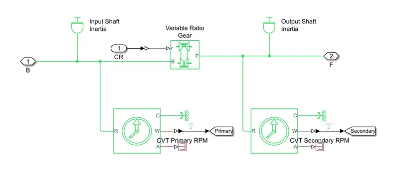
CVT mechanism:
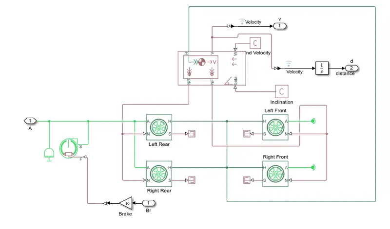
Vehicle Body:
Steps:
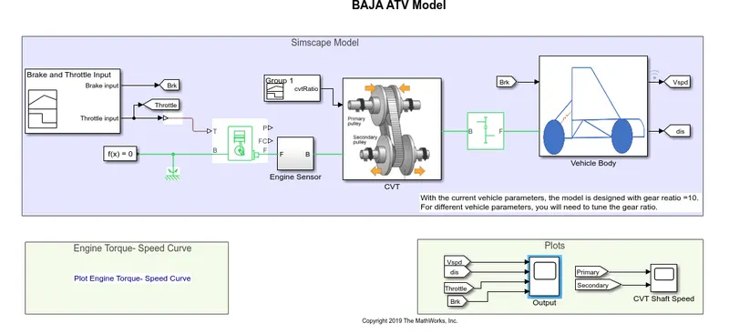
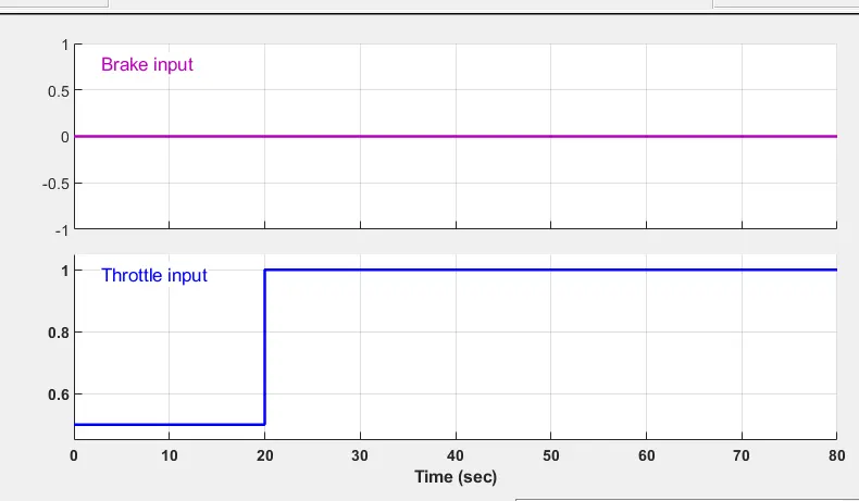
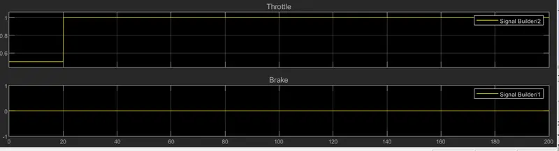
- Throttle and brake inputs are feeded to the signal builder whereas, throttle is connected to the genric engine and brake is feeded to the vehicle body as input.
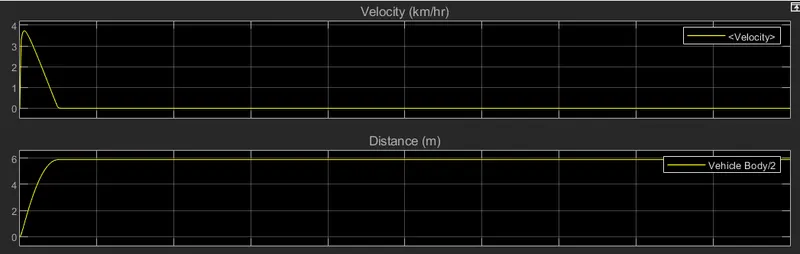
- Brake value is given as 0 and throttle is given as 0.3 for first 20seconds and then increased to 1 for the next 20 to 80 seconds
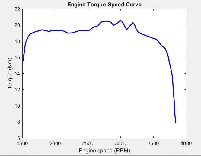
- Speed and torque vectors are predefined in workspace according to the torque speed characteristics of the vehicle and these are extracted through grabit in Matlab.
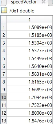
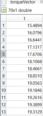
- From crank shaft output engine rpm can be found and then it is further feeded to ideal rotational motion sensor to sense the rpm.
- The speed obtained is feeded to the simple gear mechanism to reduce the speed where the gear ratio is given as 4.
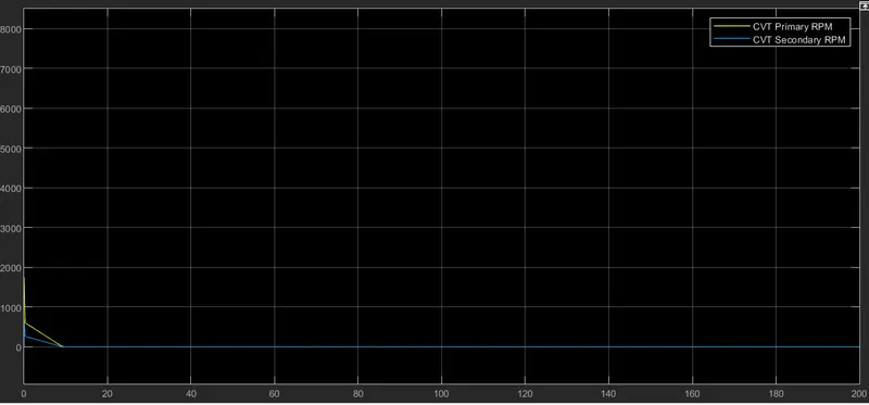
- Further the output is feeded to CVT block, then CVT ratio is feeded via signal builder. Then speed is controlled by variable cvt ratios the obtained value is feeded to vehicle axle.
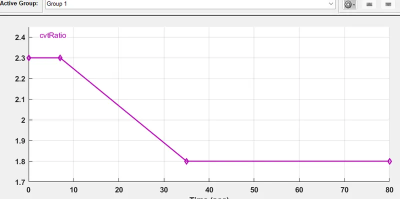
- Finally the velocity of the vehicle can be observed for further analysis.
RESULT:
Torque-Speed curve:
Velocity and Distance :
Throttle and brake:
CVT Shaft Speed:
STUDY 2- Study of BAJA ATV model with dashboard:
Simulink model:
Dashboard:
Steps:
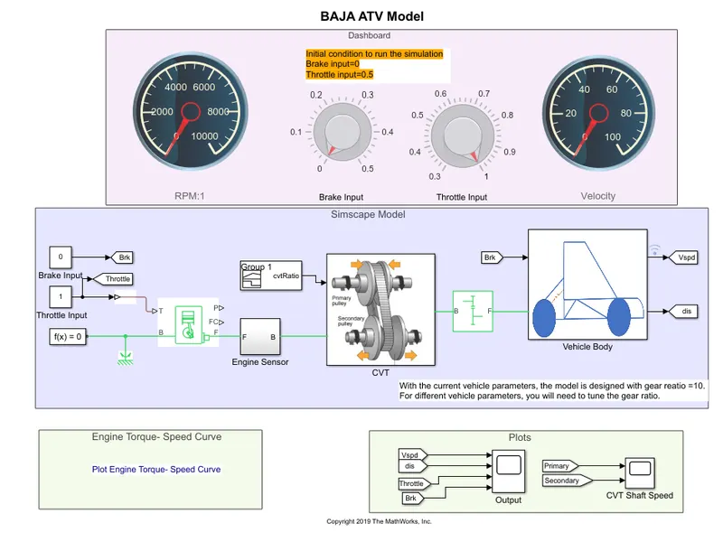
- The model workflow process is same as the process of 'Simulink Model of BAJA ATV without dashboard'.
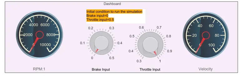
- Throttle and Brake inputs are controlled by the user with the help of knobs.
RESULT:
Engine vheicle speed:
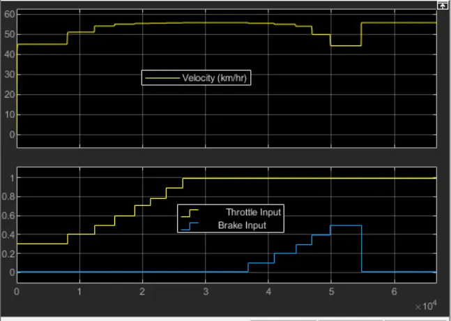
In the above figure, the velocity of the vehicle is maintained as constant for constant throttle value as 0.3 and varying by increasing the value of throttle which increases the velocity of vehicle. By increasing the brake input, the velocity of the vehicle decreasing accordingly which shown above.
CVT shaft speed:
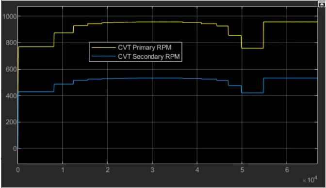
In the above figure, the primary shaft speed increases by increasing throttle and decreasing by increasing brake input value, which defines that the throttle can flow more amount of fuel which increases the power of the engine and similar to the secondary shaft. The radius of the primary shaft as more than the secondary shaft, the speed is directly proportional to the radius of the shaft. As the radius increases the speed of the shaft also increases.
STUDY 3 - Study of BAJA ATV model using lookup table without dashboard:
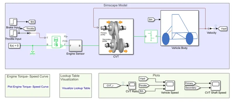
Simulink model:
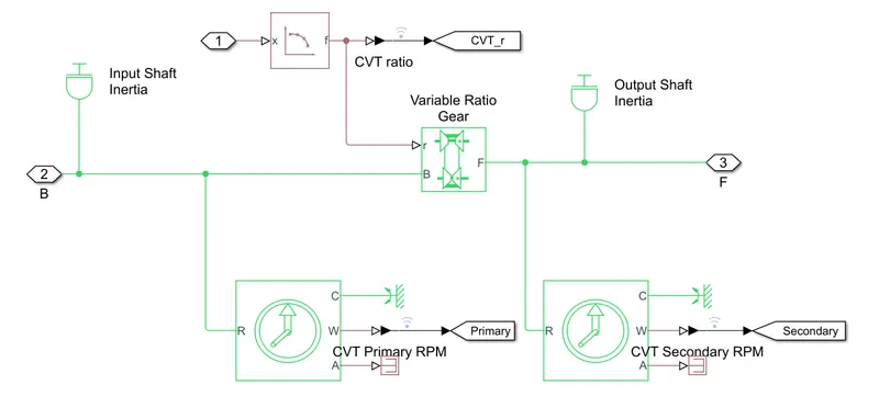
CVT mechanism:
Steps:
- The model workflow process is same as the process of Study of BAJA ATV model without dashboard.
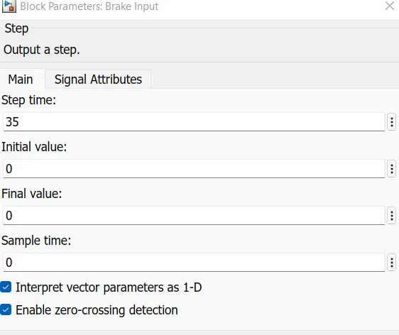
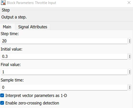
- Signal builder blocks are replaced with step blocks for brake and throttle input, step time of 35 and 20 are set and initial value of 0 and 0.3 are set respectively.
- Instead of Signal builder block for cvt ratio 2-D lookup table is used, inerpolation and extrapolation methods are set to linear.
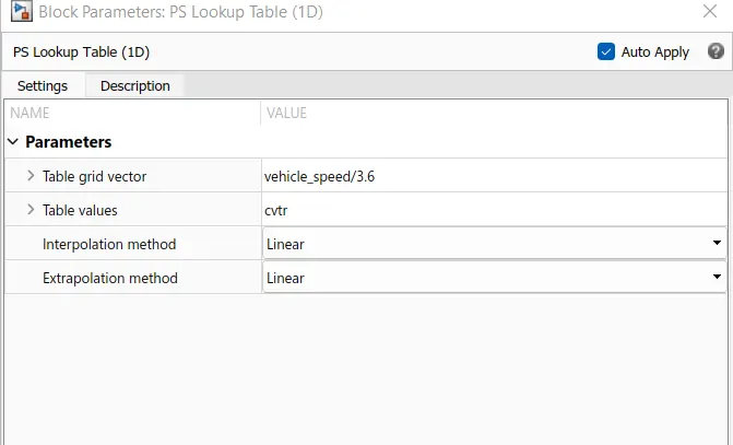
- Lastly vehicle speed output is given as feedback to the 2-D lookup table so that we can verify that the velocity of the vehicle is changing perfectly according to CVT ratio.
RESULT:
CVT ratio Vs Vehicle speed:
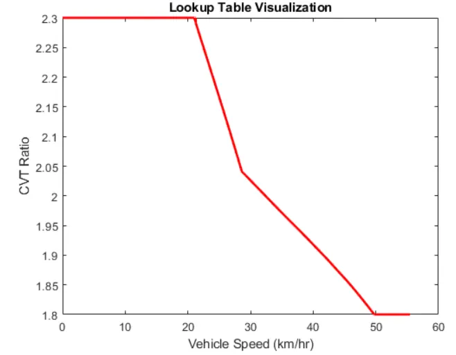
Here the CVT Ratio changes from 2.3-1.8 and the velocity value also changes w.r.t to the CVT Ratio. Hence, we can conclude that the vehicle accelerates, decelerates and remains constant when the CVT Ratio is being varied. And also, the vehicle attains the constant speed of 55.441 m/s.
Engine Speed plot:
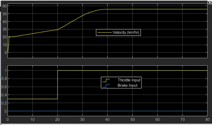
In the above figure, the brake is maintained as constant and increase in throttle which shows increase in velocity. The flow of fuel is increses when the throttle increases from 0.3 to 1, thus the power in the engine increases. The torque reaches approximately 7N-m at 1.8 gear ratio, which defines that gear ratio is directly proportional to the torque. By this gear ratio, the speed & velocity can achieve maximum. The gear ratio is assigned in lookup table and given as input to the simulink which reads every input value and obtain the result according to the input.
CVT shaft RPM:
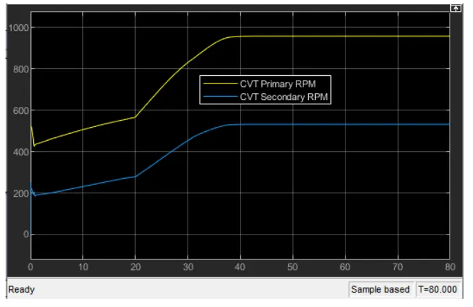
In the above figure, the primary shaft speed increases by increasing throttle and decreasing by increasing brake input value, which defines that the throttle can flow more amount of fuel which increases the power of the engine and similar to the secondary shaft. The radius of the primary shaft as more than the secondary shaft, the speed is directly proportional to the radius of the shaft. As the radius increases the speed of the shaft also increases.
STUDY 4 - Study of BAJA ATV model using lookup table with dashboard:
Simulink model:
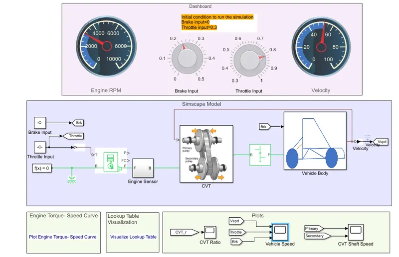
Steps:
The steps to be followed is similar to the above studies whereas the dashboard gives controlled brake and throttle inputs.
RESULT:
Engine speed plot:
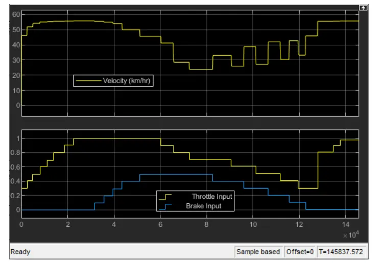
In the above figure, the velocity of the vehicle is maintained as constant for constant throttle value as 0.3 and varying by increasing the value of throttle which increases the velocity of vehicle. By increasing the brake input, the velocity of the vehicle decreasing accordingly which shown in figure18. By using lookup table, it works as closed loop by recording the velocity value and we can get at any particular value of gear ratio which is beyond the range or any random value within the range by using extrapolation and interpolation by lookup table.
CVT shaft RPM:
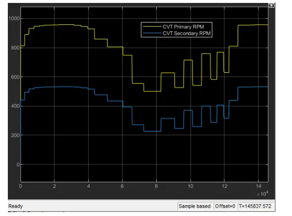
In the above figure, the primary shaft speed increases by increasing throttle and decreasing by increasing brake input value, which defines that the throttle can flow more amount of fuel which increases the power of the engine and similar to the secondary shaft. The radius of the primary shaft as more than the secondary shaft, the speed is directly proportional to the radius of the shaft. As the radius increases the speed of the shaft also increases. The throttle value and brake input value can be varying in dashboard, so we can get any particular value for input.
CONCLUSION:
Thus we have succesfully examined all the four models of BAJA AVT and presented the technical records.