Week -2
Aim :-
Make a simulink model of door bell using solenoid block and secondary aim is use a thermistor to sence a temperature of heater & turn on or turn of the fan switch as per the given condition.
Objective :-
- Primary objective is that make a door bell simulink model and Create a situation where the switch is closed for 2 seconds and then released. Observe the physical movement of the plunger.
- secondary objective is that Use a thermistor to sense the temperature of a heater & turn on or turn off the fan when Temperature source: 20 °C from 0 to 10 seconds, 27 °C from 10 to 30 seconds, 23 °C from 30 to 50 seconds Fan conditions: ON if the temperature above 25 °C, OFF otherwise.
Door bell theory :-
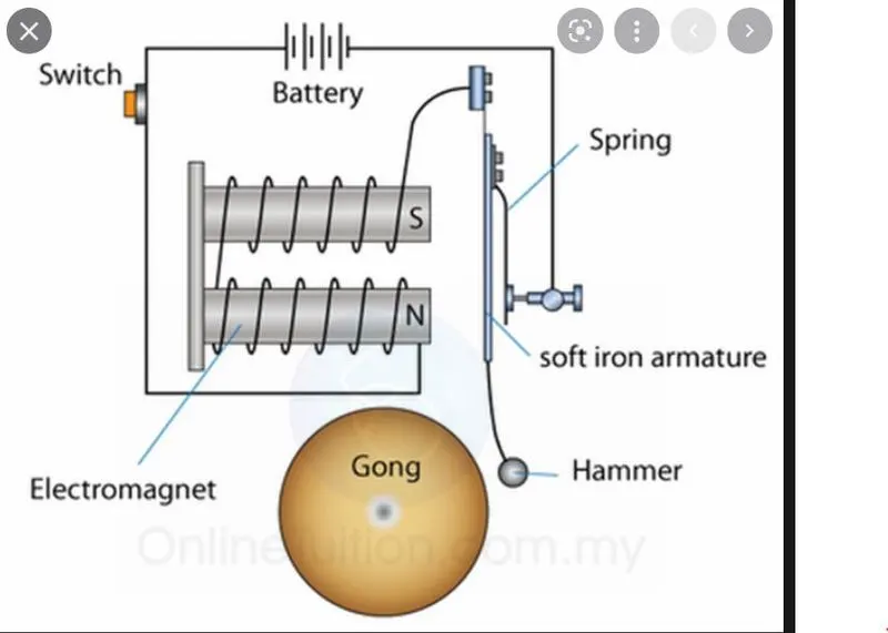
- The above shown figure is a simple door bell circuit when the switch is pushed the circuit is activated then solenoid attract the soft iron armature that's because the hammer hit on the Gong and a sound is created.
- this operation happpen many times in a couple of second so that we listen a ring sound.
- A solenoid is a common term for a wire coil used as an electromagnet. It also applies to any system that uses a solenoid to transform electric energy into mechanical energy. The system generates a magnetic field from electric current and produces linear motion using the magnetic field.
Door bell simulink model :-
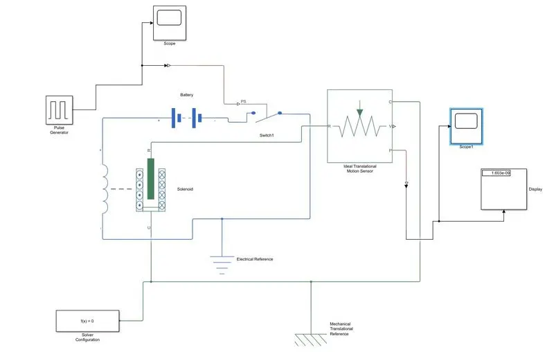
Explanation :-
- The above shown figure is a simple door bell circuit diagram, it consist of a battery,switch,solenoid and a plunger.
- So in order to taken these devices into simulink model we need the simulink block which perform same operation as the devices do.
- first we taken a solenoid block to represent the solenoid in the simulink model and a battery block to represent the battery from the Library browserr.
- Now we connect the solenoid block with Battery through battery positive terminal to the solenoid positive terminal and negative terminal to negative terminal.
- A switch block is connect between solenoid block and battery block.
- Now for the Switch to operate we need to provide a physical signal through ‘PS’ port in the ‘Switch Block’. The provided physical signal should be greater than the threshold of the switch, for switch being closed, or else it will open.
- Now this whole battery, switch and solenoid path is connected to an ‘Electrical Reference Block’ which represents earthing of the circuit. This ‘Electrical Reference Block’ should be connected with negative port of the ‘Battery Block’.
- Then in the ‘Solenoid Block’, ‘R’ and ‘C’ are two variables which represent plunger and fixed point respectively.
- Now this ‘R’ is connected to a ‘R’ of ‘Ideal Translation Motion Sensor Bock’, which senses the position of the plunger in the ‘Solenoid Block’ and gives the output.
- Now in ‘Ideal Translation Motion Sensor Bock’ the outputs are given as ‘V’ and ‘P’ which represent the velocity and position of the plunger. Since we are only interested in knowing the change in position of the plunger, so we need only results from ‘P’ output.
- Now ‘C’ in the ‘Ideal Translation Motion Sensor Bock’ is a mechanical translation conserving port, which means that the
mechanical process starts from ‘R’ and ends at ‘C’ and again it starts at ‘R’ and the cycle goes on. - So ‘C’ in the ‘Ideal Translation Motion Sensor Bock’ is connected to a ‘Mechanical Translation Reference’ which represents a fixed point where it is rigidly clamped in real time.
- Similarly ‘C’ of ‘Solenoid Block’ is also connected to the same ‘Mechanical Translation Reference’ as fixed point for the solenoid.
- Since the position of the plunger as output from ‘Ideal Translation Motion Sensor Bock’ have connected port ‘P’ of a ‘PS –Simulink Converter’ where the physical values from port ‘P’ are converted into Simulink value, and then this ‘PS-Simulink Converter’ is connected to ‘Scope Block’ which will generate a graph for change in position of plunger from port ‘P’ of ‘Ideal Translation Motion Sensor Bock’.
- Now to provide a physical signal for operating the switch, we have used a ‘Pulse Generator Block’, which generates a continuous square pulse.
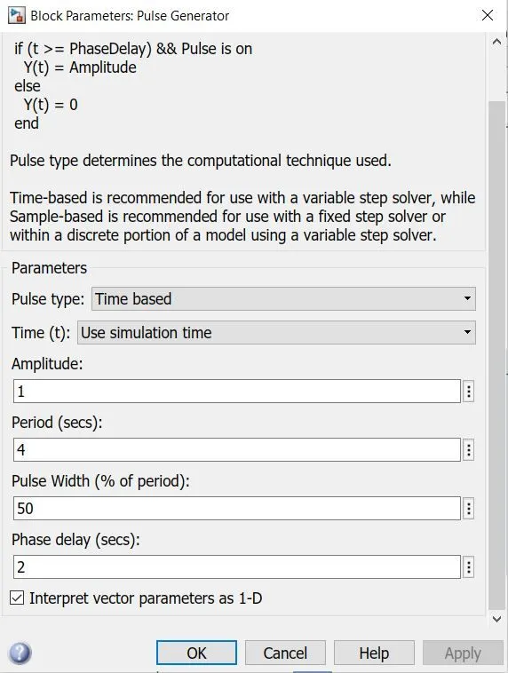
- From the above Figure we can observe that we have taken we have given period value as ‘4’, pulse width as ‘50’, phase delay as ‘2’ and amplitude by default is ‘1’ we have not changed it. This means that initially the pulse will be zero, since we have given phase delay of ‘2’ so till 2 sec the pulse will be zero and at 2 secs the pulse will start from zero to 1 since we have given amplitude as ‘1’ and then now the pulse width will half of period ,so for the next two seconds the pulse will be at amplitude ‘1’ only, then it will again come down to zero at 4 second and then it will at zero for next 2 secs thus completing the period of 4 seconds.
- From starting to ending of the pulse it will take 4 secs of time period in which only for 2 secs the amplitude will be one and for rest of time it will be zero. So, after these 4 secs period again the pulse will be generated and thus cycle continues.
- To this ‘Pulse Generator Block’ a ‘Scope Block’ is connected to see how the pulse is generated.
Input pulse :-
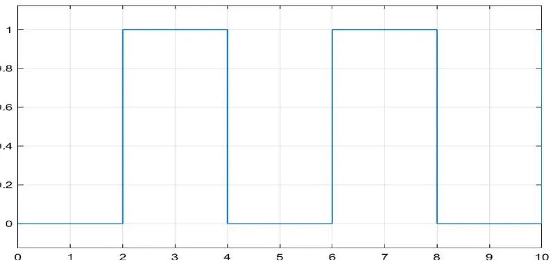
- The above figure is obtained by running the Simulink model and double clicking on the ‘Scope1’ block.
- Thus, this represents that when amplitude is one, the switch will be closed and when it is zero the switch will open. Since our objective is only to see the change in position of plunger when switch s closed for 2 secs so the we have the amplitude as 1 for 2 secs in the pulse generator by making the pulse width half of the period in the inputs for ‘Pulse Generator Block’.
- Since the pulse that is coming from ‘Pulse Generator Block’ is a Simulink value, so to convert this value into a physical value we have used ‘Simulink-PS Converter Block’, since switch only takes physical value as inputs.
- As mentioned above the port ‘P’ of ‘Ideal Translation Motion Sensor Bock’ is connected to another ‘Scope Block’, and a ‘Solver Configuration Block’ is also connected to this path which generates equations and solves the whole model internally to give the results of the whole Simulink model as output.
23. Now the run the model and double click on the ‘Scope’ Block which is connected to ‘Ideal Translation Motion Sensor Bock’ to get the results.
Output :-
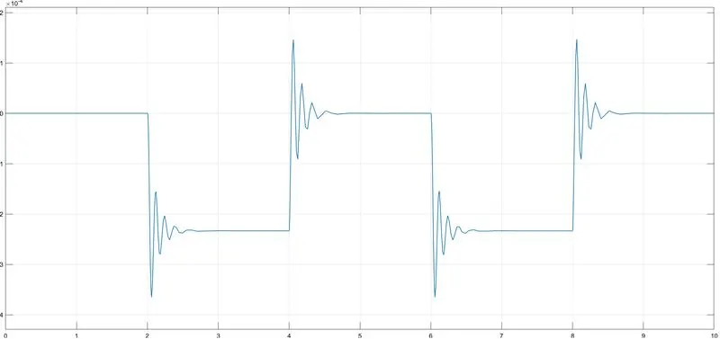
- Here x-axis represents the time in seconds and y-axis represents position of plunger in mm
- From the above figure we can observe that the initial position of the plunger is at ‘0', as from the pulse generator block, a pulse generated at 2, so in the position of the plunger is also changing at time 2 seconds and time till which the pulse amplitude is ‘1’ till that time the plunger is also at same position after the change from initial position.
- Again, as the amplitude of the pulse becomes zero, the plunger returns to its initial position back again and as the pulse cycle goes on, plunger also changes its position and comes back to its initial position.