Week -2
Simulink model of Doorbell using solenoid block.
Aim
Make a Simulink model of Doorbell using solenoid block.
Objective
To Model a simulate the working of a Doorbell as shown below
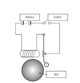
In the above arrangement, when the switch is closed the electromagnet receives electrical power from the battery and pulls the metal arm to hit the bell producing sound.
Create a situation where the switch is closed for 2 seconds and then released. Observe the physical movement of the plunger.
Solution
Solenoid is a coil of wire usually in cylindrical form that when carrying a current acts like a magnet so that a movable core is drawn into the coil when a current flows and that is used especially as a switch or control for a mechanical device (such as a valve). In our case a solenoid is used to move a metal arm which hits the bell producing sound.
Simulink Model of a doorbell
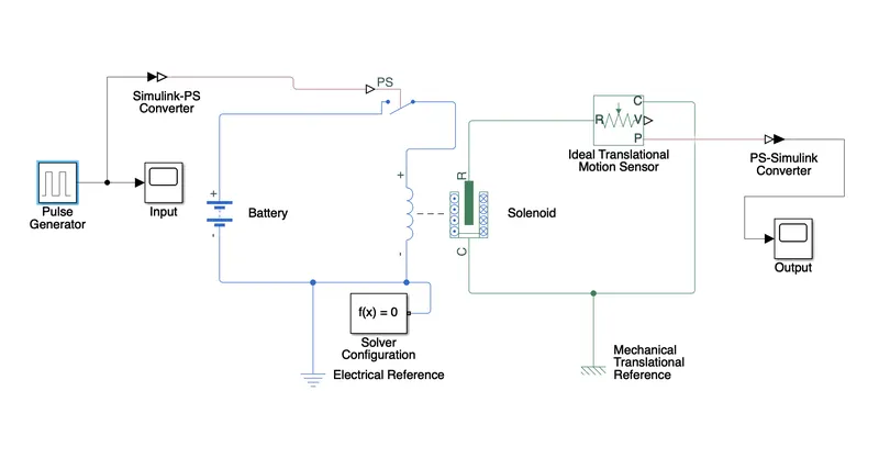
Blocks Used are:
- Solenoid
- Ideal Translational Motion Sensor
- Battery
- Switch
- Pulse Generator
- Reference Blocks (Electrical and Mechanical Translational)
- Solver Configuration Block
- Converter Blocks
- Scope
Explanation
- A Solenoid is used to move a metal arm to ring the bell. Since a solenoid is a electro mechanical device it excited using an electrical circuit with a battery and a switch.
- The position of the metal arm is sensed by the Ideal Translational motion sensor and is used to plot the position of the arm on the graph using a scope.
- A pulse generator is used to switch the circuit on and off at regular interval of time.
- Electrical and Mechanical Translational References are connected respectively and a solver configuration block is connected to define solver parameters.
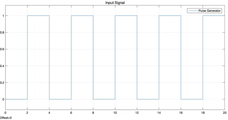
Input signal to the switch and the output of the motion sensor is shown below
Input :
Output :
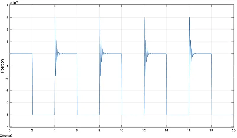
- Upon observing we can see that, when the input signal is 0, solenoid is in off state and the the plunger is at default position.
- When the input signal is 1, the switch closes and the battery excites the solenoid which causes the plunger to move and hit the bell.
- After 2 seconds the input signal becomes 0 which causes the switch to open and de excites the solenoid which causes the spring inside the solenoid causes the plunger to move to its initial position with some damping. (Spring Rate and damping coefficient can be modified as per requirement)
------------------------------------------------------------------------------------------------------------------------------------------------
Temperature Dependent ON-OFF Circuit Using Thermistor
Aim
Use a thermistor to sense the temperature of a heater & turn on or turn off the fan.
Objective
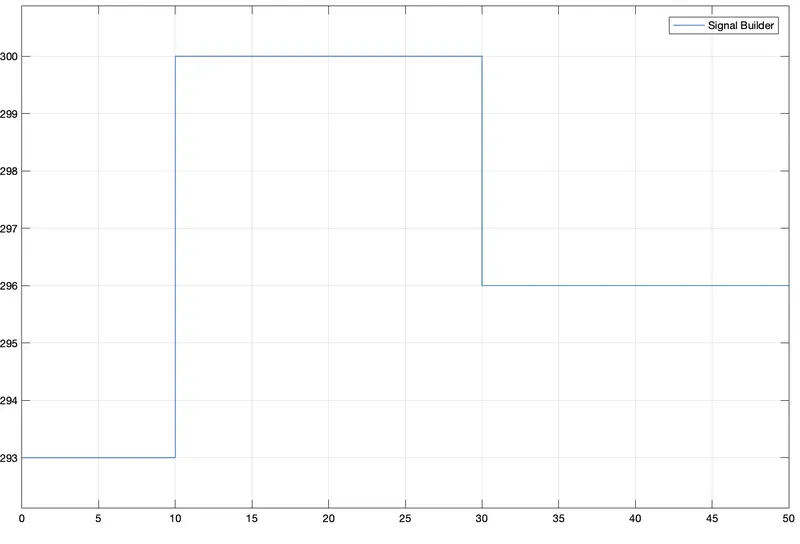
Temperature source: 20 °C from 0 to 10 seconds, 27 °C from 10 to 30 seconds, 23 °C from 30 to 50 seconds
Fan conditions: ON if the temperature above 25 °C, OFF otherwise
Solution
A thermistor is a type of Resistor whose resistance is strongly dependent on temperature, more so than in standard resistors. The word thermistor is a portmanteau of thermal and resistor.
Thermistors are divided based on their conduction model. Negative Temperature Coefficient (NTC) thermistors have less resistance at higher temperatures, while Positive Temperature Coefficient (PTC) thermistors have more resistance at higher temperatures. Hence, a PTC thermistor's resistance is Directly proportional to temperature.
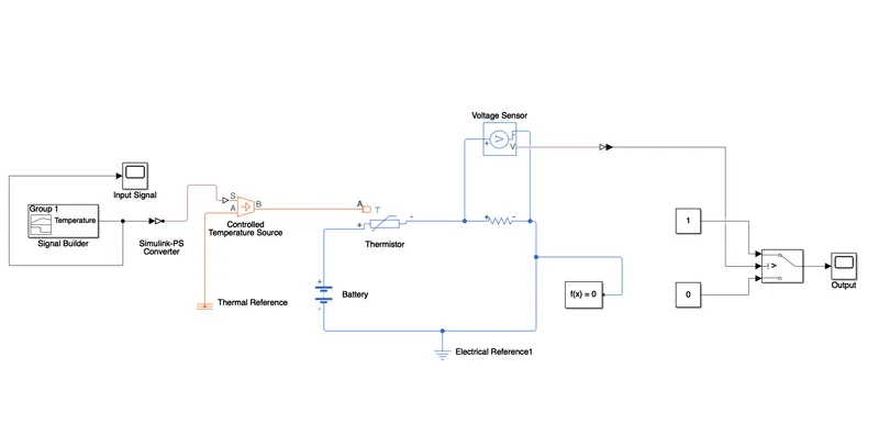
Simulink Model of the circuit
Blocks Used are:
- Thermistor
- Voltage Sensor
- Battery
- Switch
- Signal Builder
- Reference Blocks (Electrical and Thermal)
- Solver Configuration Block
- Converter Blocks
- Scope
Explanation
- For the given condition where the fan is on when the temperature is above 25 °C and OFF otherwise, a simulink switch block is used with the condition, when the input to switch is greater then the threshold the switch turns ON the fan and OFF when the the input is less than the threshold value.
- An Electrical circuit is built using a thermistor, a battery and a voltage sensor which outputs the value for the switch to use to turn fan ON or OFF.
- The input to the thermistor is simulated using a controlled temperature source which interacts between the thermal and the electrical system of simscape.
- The input signal with the given condition is simulated using a signal builder block in simulink, where the signal is built manually as mentioned.
Input Signal is shown below
- To calculate the threshold value for our circuit, the signal builder block is replaced with a constant with the threshold temperature (in K) and the output from the voltage sensor is noted as shown below.
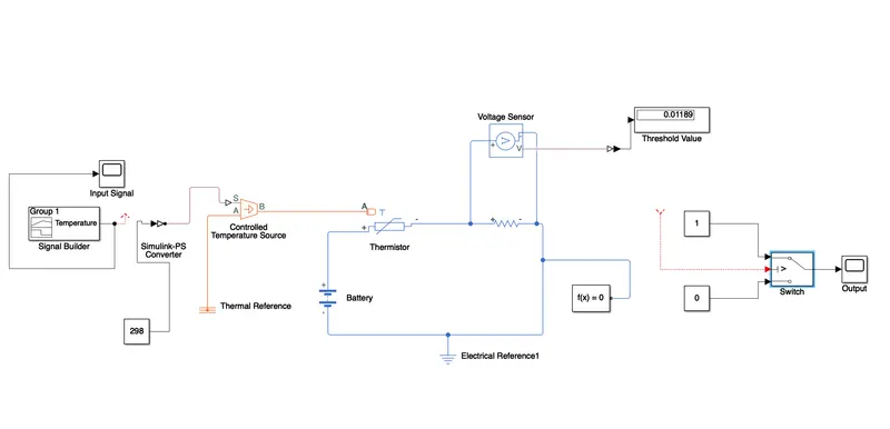
- The Threshold value for the given temperature is determined and is used in the simulink switch block to build the ON OFF logic.
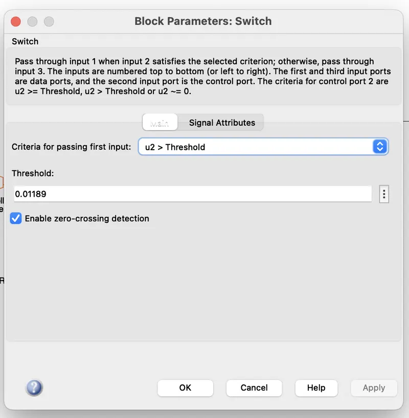
- Output of the simulation is shown below.
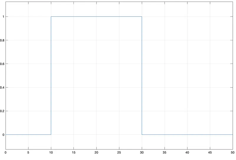
- From the above graph we can see that the value of switch from 0 sec to 10 sec is 0 which means the fan is OFF for that period where the temperature is 20 °C. In-between 10 sec to 20 sec, where the temperature is 27 °C, the value of switch is 1, which means the fan is ON from 10 to 30 seconds and after 30 seconds the value of switch is 0 again, which indicates the fan is OFF.