Week -2
Objectives:
- To make a Simulink mode of doorbell using a solenoid block in a situation where the switch is closed for 2 sec and then closed.
- To use a thermistor to sense the temperature of heater & turn on Temperature source: 20 °C from 0 to 10 seconds, 27 °C from 10 to 30 seconds, 23 °C from 30 to 50 seconds Fan conditions: ON if the temperature above 25 °C, OFF otherwise
- Doorbell working principle,
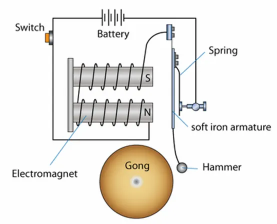
The most important part of a door bell is its magnetic motor. The magnetic motor constitutes a conventional electromagnet. We know that an electromagnet is an arrangement in which a coil of wire is wrapped around magnetic material which produces magnetic field when electricity is passed through the coil. The greater the coiling of the wire, the higher the amplification of magnetic field. This magnetic field produces a substantial effect on any magnetic substance when brought in the vicinity of its magnetic field. This means that when an iron object is placed in this magnetic field, it will be attracted towards the magnetic field due to polar orientation generated by the electromagnetism.
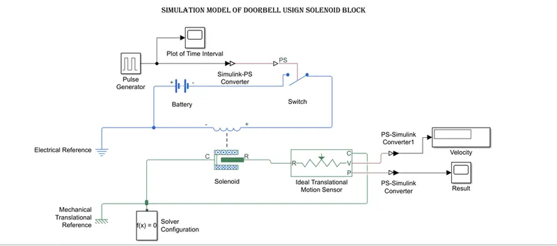
Blocks are used:
- Pulse Generator: For generating a time interval to control the switch
- Simulink – PS Converter: To Convert Simulink system to physical system
- Battery: Is used for power supply
- Switch: To control the flow of current through battery.
- Scope: To view the plot of time interval velocity and position of metal hammer.
- PS – Simulink Converter: To convert physical system to Simulink system
- Electric reference: to Grounding/Earthing the all-electrical blocks
- Mechanical Transitional reference: To grounding the all-Mechanical blocks.
- Solver Configuration: Defines solver settings to use for simulation
- Solenoid Block: To generate the electromagnetic force to attracts the hammer
- Ideal Translational motion sensor: this device will convert an across variable that measured between two mechanical translation nodes into a control single proportional to velocity and position.
- Display Block: To display the velocity and position values,
Procedure:
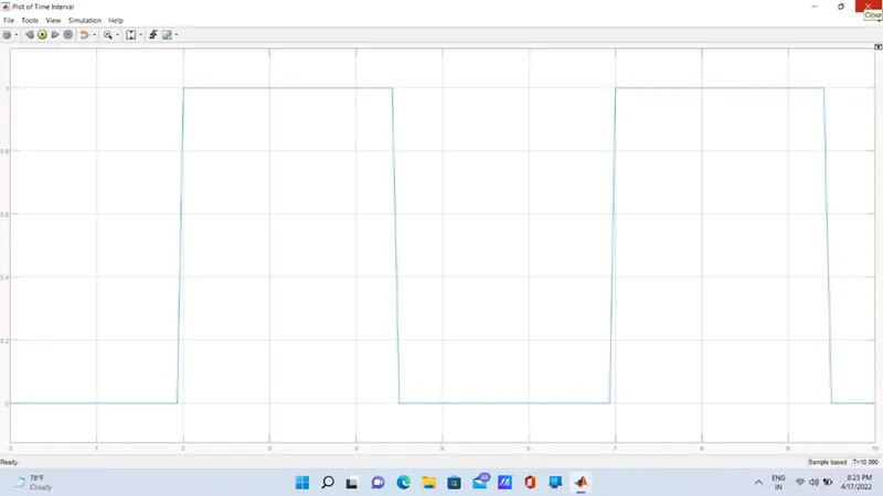
- In the pulse generator signals are generator for every 2 sec to control the switch to ring the bell
- According the signals the switch operates. When the switch is closed the electric power will flow through the solenoid and it creates EMF
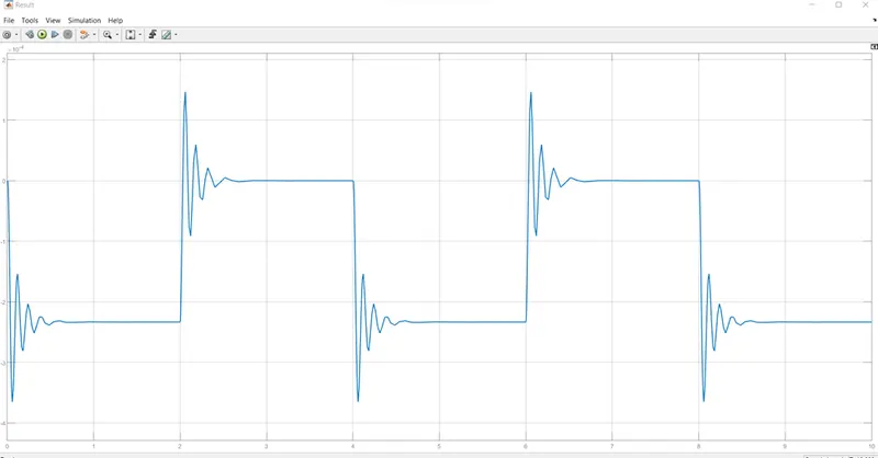
- This EMF creates the motion of hammer to hit the bell by the ideal translational motion sensor, the hammer will be known and recorded when PS- Simulink converted is added
Output: -
- Time interval plot
- Result
Conclusion:-
- By observing the result, the bell is rung for every 2 sec in the span of 10 sec.
- In time pulse generator we can observe some deviation in the plot, this are not resolved by TSE also
Thermistor:
Thermistors are temperature-dependent resistors, changing resistance with changes in temperature. They are very sensitive and react to very small changes in temperature. They are best used when a specific temperature needs to be maintained, and when monitoring temperatures within 50° C of ambient.
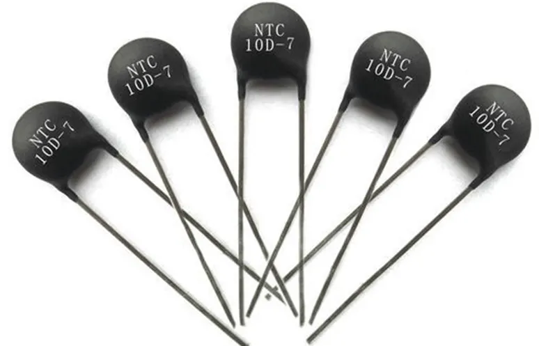
Thermistors, as a part of a temperature control system are the best way to measure and control heating and cooling of a Peltier device. Their ability to adjust in minute increments allow the greatest overall system stability. Thermistors can be embedded in a surface-mounted on the device needing temperature monitoring. Depending on type, they can measure fluids or solids. They are made up of metallic oxides.
Input Temperature:
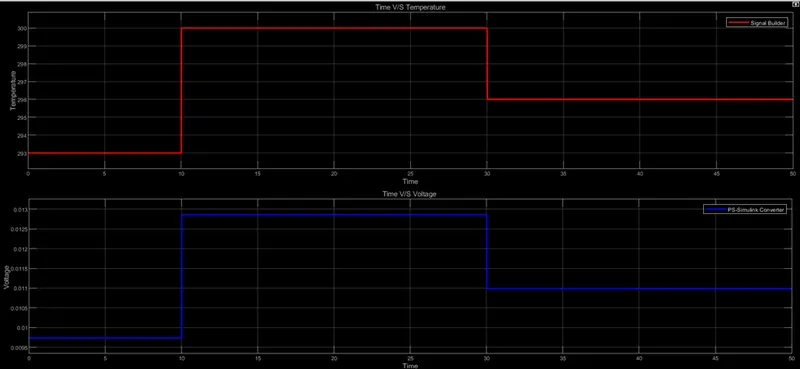
T = 200 C from 0 to 10 sec
T = 270 C from 10 to 30 sec
T = 270 C from 30 to 50 sec
Fan Condition is:
ON if T > 270 C
Else OFF
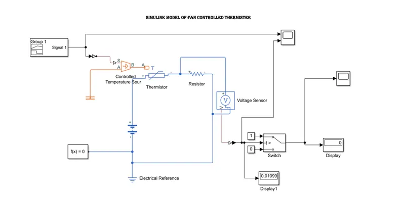
Blocks used:
- Thermistor: This block represents an NTC thermistor using the B parameter equation. The resistance at temperature T is given by R(T) RO*exp(B* (1/T-1/TO)) where RO is the Nominal resistance at the reference temperature TO, and B is the Characteristic temperature constant. The temperature T of the thermistor is governed by the equation m*c*dT/dt = Q where Q is the net heat flow into port A, m is the mass and c is the lumped specific heat capacity. The thermal mass m*c is calculated from the Thermal time constant t_c and the Dissipation factor K_d using the equation m*c = K_d*t_c. =
- Resister: The voltage-current (V-I) relationship for a linear resistor is V=I*R, where R is the constant. resistance in ohms.
- Signal builder: To build the input Temperature signals
- Scope: Used for plotting
- Simulink-PS converter: Converts the Simulink input signal to a Physical Signal.
- Controlled Temperature source: This block represents an ideal energy source in a thermal network that can maintain a controlled temperature difference regardless of the heat flow rate. The temperature difference is set by the physical signal port S. A positive temperature difference causes the temperature at port B to be greater than the temperature at port A.
- Temperature sensor: To sense the temperature. This block measures temperature in a thermal network. There is no heat flow through the sensor. The physical signal port T reports the temperature difference across the sensor. The measurement is positive when the temperature at port A is greater than the temperature at port B.
- Thermal reference: To grounding the thermal network
- Electrical reference: To grounding the electrical network
- Mechanical rotational reference: To ground the mechanical rotational parts
- Slover configuration: Defines solver settings to use for simulation.
- Battery: Power source
- Voltage sensor: To sense the threshold voltage.
- Switch: condition switch to control based on threshold value.
- Controlled voltage source: To regulate the voltage.
- DC motor: Used as a rotating device
- Ideal rotational motion sensor: To sense the angular velocity and angular displacement of a DC motor.
Flow process:
- We need to define the inputs required in signal builder to provide the signal to thermistor through controlled temperature source. Simulink-PS converter is used to convert the signals to physical system.
- Through voltage sensor the threshold voltage is calculated. Through this threshold value the switch operates to control the fan/DC motor. By using the ideal rotational motion sensor, the angular velocity and displacement values were calculated and recorded by using PS-Simulink converter in display and scope.
Output
- Input temperature and Voltage
- Fan condition ON and OFF
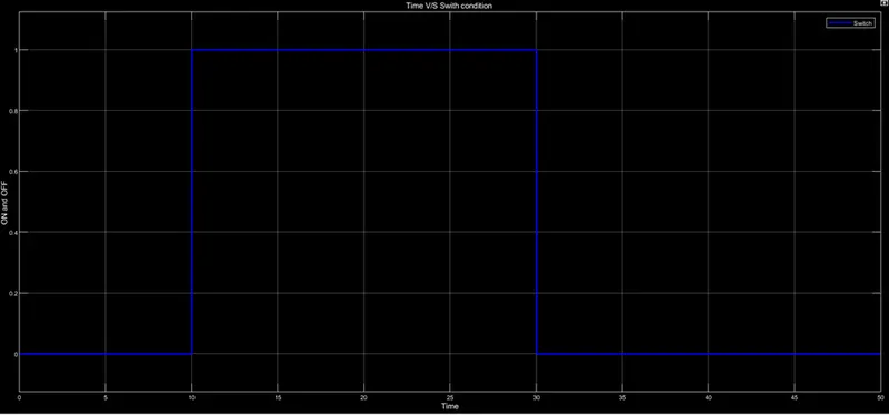
Conclusion:- By observing the out model run correctly Hence the Simulink models of fan controlled thermistor are satisfied the condition given
Reference: