Engine kinematics: writing program to plot PV diagram for otto cycle using MATLAB
Engine kinematics:
- writing program to plot PV diagram for otto cycle,
- calculating the thermal efficiency of the otto cycle,
- In otto cycle we have 4 processes as below,
1 – 2 = Isentropic Compression process,
2 – 3 = Constant Volume Heat addition process, (V2=V3
3 – 4 = Isentropic Expansion process,
4 – 1 = Constant Volume Heat rejection process, (V4=V1)
- If we want to plot P – V diagram we need to calculate all state variables, (P, V, T)
Assuming: -
- P1 = 1 atm = 101325 pascal
- T1 = 350 kelvin (minimum temperature of the engine)
- T3 = 1800 kelvin (maximum temperature of the engine)
- Gamma = 1.4
- Engine geometric parameters
- Bore = D = 0.1 m
- Stroke = L = 0.1m
- Connecting rod length = 0.15
- Compression ratio =CR =9
- Formula used in the program,
- Calculating the swept volume and clearance volume by
- V swept = π/4 (D^2 * L) = V1
- V clearance = (V swept )/(cr-1) = V2
- Perfect gas law equations w r t the process
- I `(P2V2)^γ=(P1V1)^γ`
`strong>`P2=P1(v1)/(v2)^γ)=P1CR^γ`
- (P1V1/T1)=(P2V2/T2)
T2=(P2V2T1)/(P1V1)
- `(P3V3)/(T3)=(P2V2)/(T2) (V3=V2)`
`P3=(P2T3)/(T2)`
- `(PV2)^γ=(P1V1)^γ`
`P4=P3(V3/V4)^γ`
- `(P3V3)/(T3)=(P4V4)/(T4)`
`T4=(P4V4T3)/(P3V3)`
- In both isentropic process pressure & volume will changing with constant temperature, to obtaining the PV diagram correctly we need to use the ‘Engine kinematics formula’ with a function to calculate the V and P
`V/(V swept)=1+ 1/2(CR-1)[R+1-COS(θ)-(R^2-SIN^2 (θ)^(1/2)]`
where, R = ratio of connecting rod to crank pin radius(a)
crank pin radius = L/2
- writing the function to trace the volume in different angles,
theta = linsapce(start crank, end crank, 100)
[v] = IC_Engine (bore, stroke, con_rod, cr, start crank, end crank)
In 1-2 start crank angle & end crank angle = (180 to 0) BDC to TDC
In 2-3 start crank angle & end crank angle = (0 to 180) TDC to BDC
2. Writing the command to trace the pressure in both isentropic processes using the perfect gas law equation
`(PV)^γ=Constant`
`P=Constant*V^γ`
-
Calculating the thermal efficiency of otto cycle
`ղ=1-1/(cr^(γ-1) )`
-
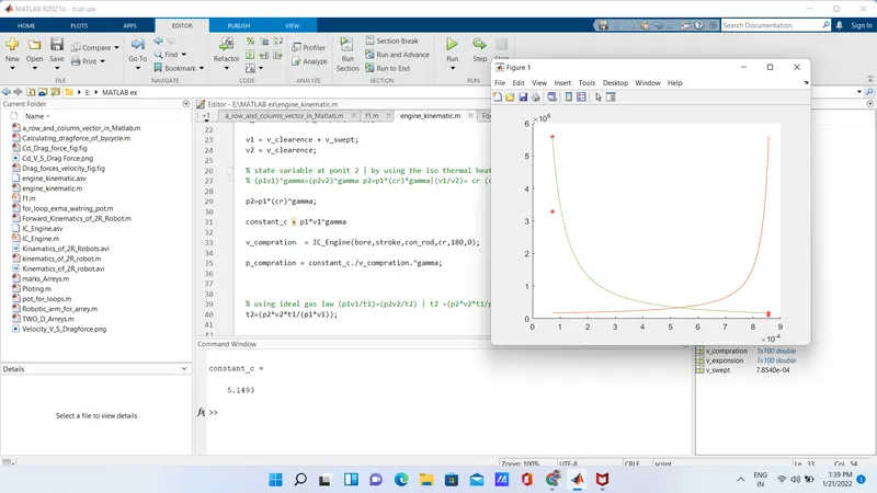
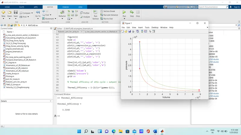
pressure v/s volume Plotting done
-
error faced while writing program,
- Given wrong command in function and correction done
- Minor mistake in spelling correction is done,
- Got undefine graph due to wrong command given in the plotting
- Got wrong answer due to brackets are missed in formula
- Got error in multiplication of matrix, element vise operator missing
- program
% Engine kinematics: writing program to plot PV diagram for otto cycle using MATLAB,

close all
clc

% inputs,
t3 = 1800;
gamma = 1.4;

%engine geometric parameters
bore = 0.1;
stroke = 0.1;
con_rod = 0.15;
cr = 9;

% state variable at point 1 | considering p1 = 1 atm  and t1 = 350k, and calculating the v1 & v2
p1 = 101325;
t1 = 350;

v_swept = (pi/4)*bore^2*stroke;
v_clearence = (v_swept/(cr-1));

v1 = v_clearence + v_swept;
v2 = v_clearence;

% state variable at ponit 2 | by using the iso thermal heat addition process
% (p1v1)^gamma=(p2v2)^gamma p2=p1*(cr)*gamma|(v1/v2)= cr (compression ratio)

p2=p1*(cr)^gamma;

% using the function to understand the volume in the enging w r t theta
% while in campression process the piston will move from BDC to TDC, crack angle = (180 to 0)

constant_c = p1*v1^gamma;

v_compression  = IC_Engine(bore,stroke,con_rod,cr,180,0);

p_compression = constant_c./v_compression.^gamma;

% using ideal gas law (p1v1/t1)=(p2v2/t2) | t2 =(p2*v2*t1/p1*v1)(p2*v2*t1/p1*v1)
t2=(p2*v2*t1/(p1*v1));

%state variable at point 3 | and t3 = 2300k
% using ideal gas law (p2v3/t3)=(p2v2/t2) | p3 = p2*t3/t2
v3=v2;
p3 = (p2*t3)/t2;

% using the function to understand the volume in the enging w r t theta
% while in expasion process the piston will move from TDC to BDC, crack  angle = (0 to 180)

constant_c = p3*v3^gamma;
v_expansion  = IC_Engine(bore,stroke,con_rod,cr,0,180);

p_expansion = constant_c./v_expansion.^gamma;


%state variable at ponit 4 | (p3v3)^gamma=(p4v4)^gamma |(p3v3/t3)=(p4v4/t4)
v4=v1;
p4=p3*(v3/v4)^gamma;

t4 = (p4*v4)*t3/(p3*v3);

figure(1)
hold on
plot(v1,p1,'*','color', 'r')
plot(v_compression,p_compression)
plot(v2,p2,'*','color', 'r')
plot(v3,p3,'*','color', 'r')
plot(v_expansion,p_expansion)
plot(v4,p4,'*','color', 'r')

line([v2,v3],[p2,p3],'color','b')
line([v4,v1],[p4,p1],'color','m')

xlabel('Volume')
ylabel('pressure')
grid on

% Thermal efficency of otto cycle = output/ input,

Thermal_Efficency = 1-(1/(cr^(gamma-1)));
result
error faced