Week -2
Q1) Simulink model of a door bell using solenoid block with following details
Solenoid
A solenoid is a device comprised of a coil of wire, the housing and a moveable plunger (armature). When an electrical current is introduced, a magnetic field forms around the coil which draws the plunger in. More simply, a solenoid converts electrical energy into mechanical work.
1) The coil is made of many turns of tightly wound copper wire. When an electrical current flows through this wire, a strong magnetic field/flux is created.
2) The housing, usually made of iron or steel, surrounds the coil concentratinf the magnetic field generated by the coil.
3) The plunger is attracted to the stop through the concentration of the magnetic field providing the mechanical force to do work.
Circuit design and Input condition
Circuit design
Input condition
Switch is closed for 2 seconds
1) AIM
To observe and analyze the motion of plunger during the switch on and off condition w.r.t time.
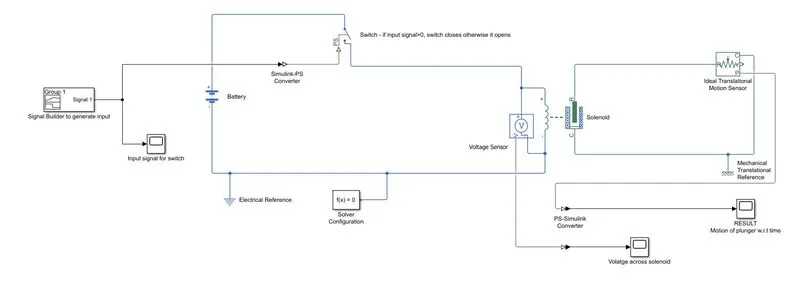
2) SIMULINK MODEL CREATION WITH GIVEN INPUT CONDITION
(i) Input signal generation
a) Signal builder
Select signal builder block from sources in library browser, create a signal whose output is 1 for 0 to 2 seconds and zero for the remaining time.
Block selection can be also be done by directly typing the block name in the search box of library browser
(ii) Circuit development
Components of circuit
a) Battery
A DC voltage source is supplied to the solenoid block to activate the door bell.
DC voltage selected is 50V. The rated voltage of Solenoid and Input DC voltage should be same.
b) Switch
Used to ON or OFF the voltage supply to Solenoid automatically. This block takes a physical signal as input. The switch closes if the given signal is greater than the threshold (given parameter) and closes otherwise. The threshold value given here is 0 i.e., if the physical signal input is greater than zero, the switch closes and opens otherwise.
c) Solenoid
Solenoid comprises of a coil of copper wire and a plunger with a spring. When the current flows through the copper wire, a magnetic field is generated and this magnetic flux is concentrated along the plunger. This makes the plunger act like a magnet with magnetic lines of force moving from North to South poles. Due to this magnet like behavior of plunger, it moves towards or away from the object. When the switch closes, plunger moves towards the object and the bell rings.
d) Ideal translational motion sensor
This block detects the motion of plunger and plots its motion w.r.t time for analysis. Since the motion of plunger is translational, a translational motion sensor is selected.
Measurement sensor
Voltage sensor
This block measures voltage between two electrical connections and represents it as a physical signal.
References
Mechanical translational reference
The Mechanical Translational Reference block represents a reference point, or frame, for all mechanical translational ports. All translational ports that are rigidly clamped to the frame (ground) must be connected to a Mechanical Translational Reference block. In solenoid, R port is a movable member and C port is stationary i.e., the plunger movement is detected by the motion of R. Therefore, C port is connected to mechanical translational reference.
Electrical reference
The Electrical Reference block represents an electrical ground. Electrical conserving ports of all the blocks are connected to electrical reference.
Solver
Solver configuration
It provides solver settings information for simulation of the model. This block specifies solver parameters that the model requires before the simulation begins.
Signal converter
Simulink-PS converter
Converts input Simulink signal to output Physical Signal
PS-Simulink converter
Converts input Physcial Signal to output Simulink Signal
Scope
Used for observation and analysis of output, it displays signals w.r.t time.
SIMULINK MODEL
Voltage input to solenoid
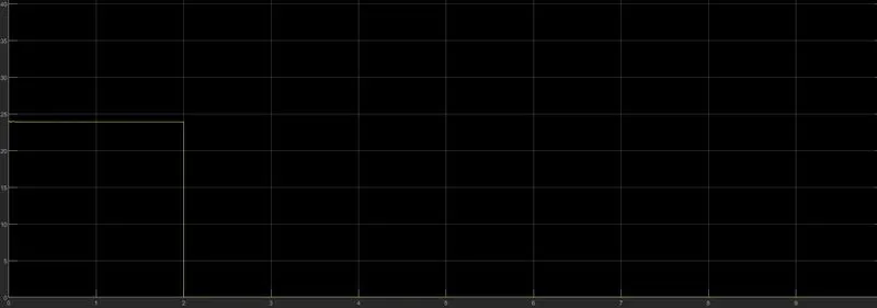
From the plot, it can be observed that the input specified voltage (24V) is supplied for 2 seconds to the solenoid. The input voltage supply is only for 2 seconds because it is controlled by the switch position. The switch position is in turn controlled by the input signal. When the input signal to switch is greater than zero, the switch closes and a voltage of 24V from the battery is supplied to the solenoid. The input signal to switch > 0 for 2 seconds, therefore the input voltage supplied to solenoid is also for 2 seconds.
3) RESULTS & OBSERVATIONS
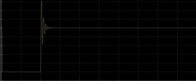
(i)Position of plunger
From the plot, it can be observed that the plunger moved from position 5 to 0 ( a distance of 5mm). Here, X=5 is starting position of plunger and x=0 is the final position of plunger. The stroke or air gap is 5mm, that means at x=0, the plunger is in contact with the object and can’t move any further. The plunger is in position x=0 for 2 seconds and returns to original position after that. As the supply voltage is only for 2 seconds, the magnetic generated by solenoid is also for 2 seconds and therefore, the plunger moves rings the doorbell for 2 seconds.
(ii)Oscillations of plunger
Damped oscillations of the plunger about its original position can be observed after the input supply is cutoff. These oscillations are due to the presence of spring connected to plunger. The plunger when it is in position x=5, the spring is subjected to an external force. As the input voltage supply cuts off, the restoring force of the spring makes the plunger to return to its original position but with some oscillations about the original position. The amplitude of oscillations depend on the restoring force, as the distance moved by plunger is fixed, the restoring force can be varied using spring constant. As the spring constant is more, the restoring force is more and amplitude of oscillations is more. The oscillations are damped as the damping parameter can be given as input to solenoid block. As the damping parameter value is increased, the amplitude and sustainability of oscillations are reduced.

2) THERMISTOR CHALLENGE
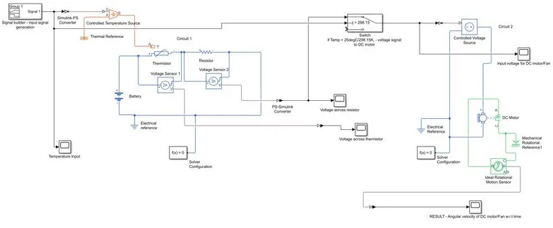
Q2) Use a thermistor to sense the temperature of heater and turn on or turn off the fan as per the below conditions.
Input condition: 0 to 10 seconds, temperature: 20degC
10 to 30seconds, temperature: 27degC
30 to 50seconds, temperature: 23degC
Output response condition: fan should turn on if temp > 25degC otherwise turn off
1) AIM
To turn on the fan when the thermistor senses a temperature of heater greater than 25degC.
(i) Input signal generation
a) Signal builder
Select signal builder block from sources in library browser, create a signal whose output is 293.15K for 0 to 10 seconds, 300.15K for 10 to 30seconds and 296.15K for 30 to 50seconds.
b) Controlled Temperature Source
This block maintains a controlled temperature difference regardless of heat flow rate. Temperature difference is set by signal port S. If the temperature at port B is greater than port A, then it is a positive temperature difference.
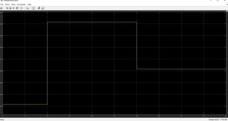
(ii) Circuit development
Components of circuit1
a) Battery(DC voltage source)
Voltage selected: 12V
b) Thermistor
A thermistor(or thermal resistor) is defined as a type of resistorwhose electrical resistance varies with changes in temperature. The resistance of thermistor decreases with increase in temperature. This characteristic of this thermistor makes it attain a negative temperature coefficient( decrease in resistance as temperature increases). Because of this nature, a thermistor is also called as NTC thermistor.
A thermistor block senses the temperature from port A and in response to the change in temperature, its resistance varies accordingly.
c) Resistance
This block represents resistance. The voltage across resistor is given by V(+) and V(-) and the sign of current is positive when it flows through the device from positive to negative.
The resistance value given: 1000ohms
Measurement sensors
Voltage sensors are connected across Thermistor and resistance.
References
Electrical reference
Electrical conserving ports of all the blocks of the circuit1 are connected to electrical reference.
.
Thermal reference
This block represents a reference point where temperature is absolute zero.
Solver configuration
Solver parameters specified for circuit1 for simulation.
CONDITION
The voltage across resistor at a temperature greater than 25degC is an input to electric motor or fan.
LOGIC
Switch block is selected to execute the condition. This block has three input ports, one for the condition and other two for inputs. If the condition satisfies, it will allow the one input to pass through and stops the other. If the condition is not satisfied, then vice versa.
The temperature signal is provided to condition port of Switch block, the threshold value for switch block is given as 298.15K(25degC). One input is voltage drop across resistor and no input to other input port. If the temperature signal is greater than 25degC, then it will pass the voltage signal across the resistor as input to the electric DC motor or fan otherwise it will be zero.
Components of circuit2
a) Controlled voltage source
An ideal voltage source and maintains the specified voltage irrespective of the current passing through it. The output voltage across resistance is connected to controlled voltage source.
b) Electric DC motor
This block represents electrical and torque characteristics of a DC motor. The output of Controlled voltage source is connected to this motor.
c) Ideal rotational motion sensor
This block detects the rotational motion of the rotor in DC motor. This block helps in detecting and angular velocity and position of the rotor w.r.t time.
References
Mechanical rotational reference
This block is used to fix mechanical rotational parts to frame or ground.
Electrical reference
Electrical conserving ports of all the blocks of the circuit2 are connected to electrical reference.
Solver configuration
Solver parameters specified for circuit2 for simulation.
SIMULINK MODEL
3) RESULTS & OBSERVATIONS
Voltage drop across Themistor
Voltage drop across Resistor
(i)Voltage drop across Resistor
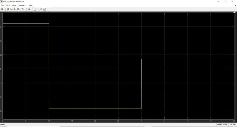
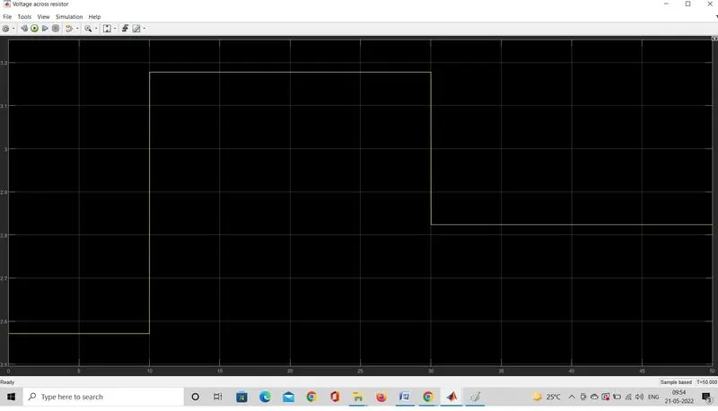
From the plot, it can be observed that the voltage drop across the resistor is varying w.r.t time. In this circuit, there are two resistors, one is a variable resistor and other is a fixed resistor. Since there are two resistors, voltage drop occurs across both of them. The voltage drop is varying across the fixed resistor. Reason: As the temperature is 20degC, voltage drop across thermistor is 9.425V and voltage drop across resistor is 2.575V (measured using cursor measurement) and if the voltage drops are summed up, we obtain the supply voltage value i.e., 12VDC. In a DC circuit, sum of voltage drops = total supply voltage. Similarly, the voltage drop across the resistor changes for remaining time intervals of 10 to 30sec and 30 to 50 sec.
(ii)Voltage drop across Resistor as input to DC motor
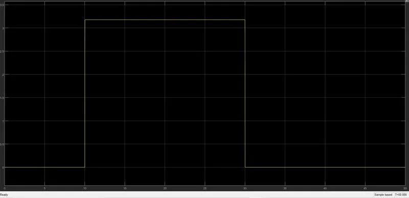
From the plot, it can be observed that the voltage at time interval of 10 to 30 seconds is considered as input to DC motor. This is because the at this time interval , the temperature is greater than 25degC or 298.15K. The switch block checked for the condition of temperature greater than 298.15K, the condition satisfied at time interval of 10 to 30 seconds, therefore it passes the voltage (voltage drop across resistor at time interval of 10 to 30 seconds) as input to DC motor.
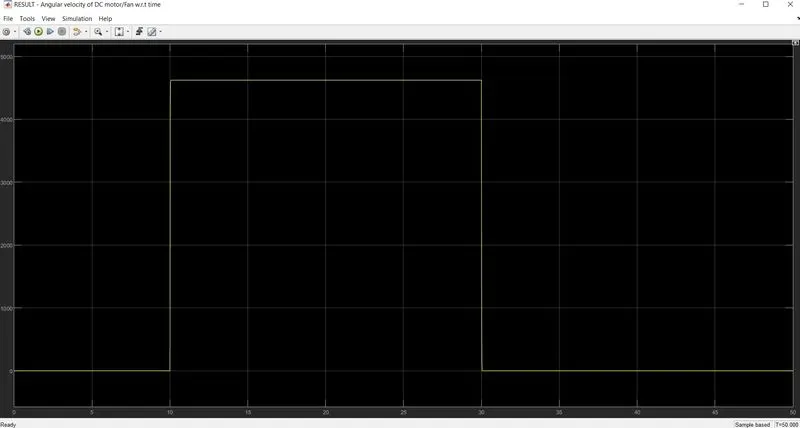
(iii) ON and OFF condition of DC motor and Angular velocity
From the plot, it can be observed that the angular velocity is approximately 4600rad/s and it is only for a time interval of 10 to 30 seconds and remains zero at other time intervals. This is because the supply voltage to DC motor or DC motor turns on only when temp > 25degC.
COMMENTS
Dear sir,
I have tried converting the files to lower version. It is showing the following error.
(unable to convert due to simscape electrical blocks)
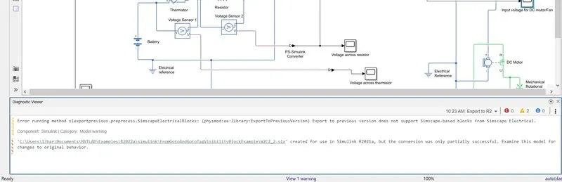
Therefore, I have attached the 2022a version files . I request you to kindly consider them.