Week -2
Make a Simulink model of Doorbell using solenoid block
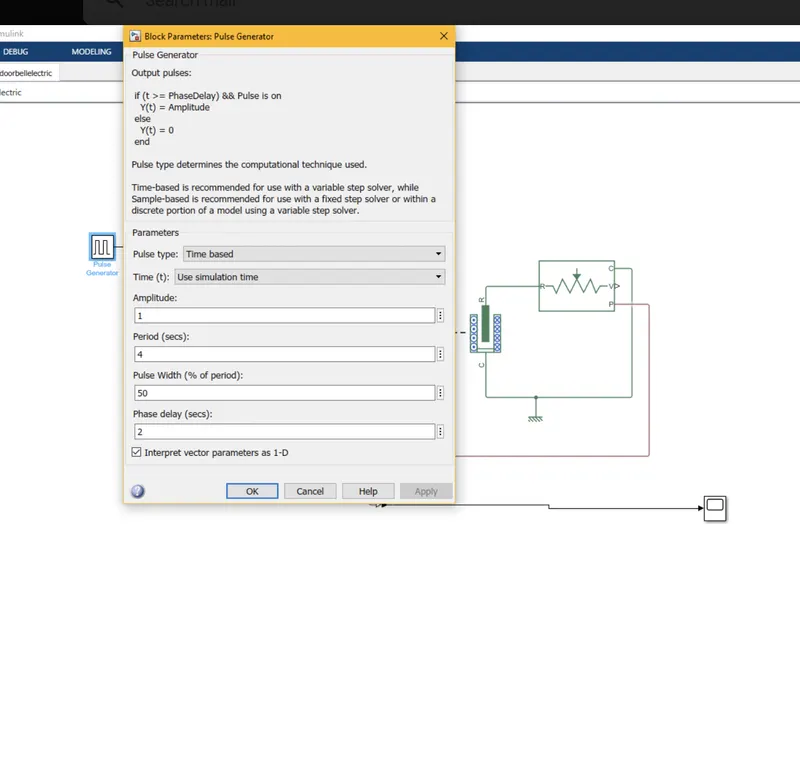
The electric door bell consists of dc voltage source, switch, a soleniod with plugger and the bell.
To simulink the model of the electric door bell, we need to know the characterstics of the solenoid when current passes through it.
Solenoid :
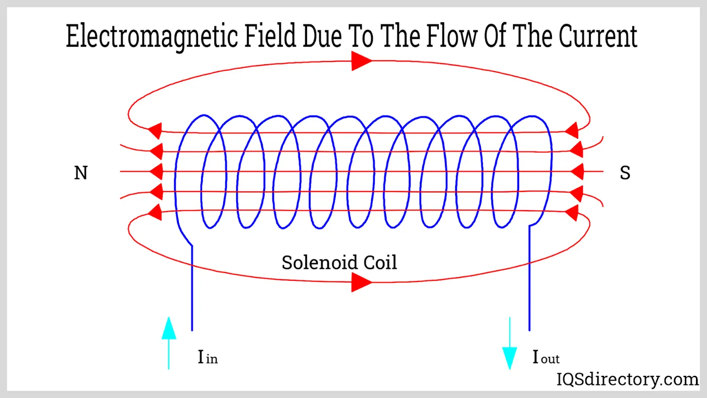
A solenoid is a simple coil, when it is subjected to current the magnetic field forms with respect to the direction of the current. When a iron particles are subjected to the coil it will get attracted. The same phenomenon is applied in the electric door bell.
STEPS TO MODEL SIMPLE DOOR BELL USING SOLENOID BLOCK:
- solenoid block
- pulse generator
- dc voltage source
- switch
- electrical/mechanical refrence
- Ideal mechanical transtional sensor
- scope
- solver block
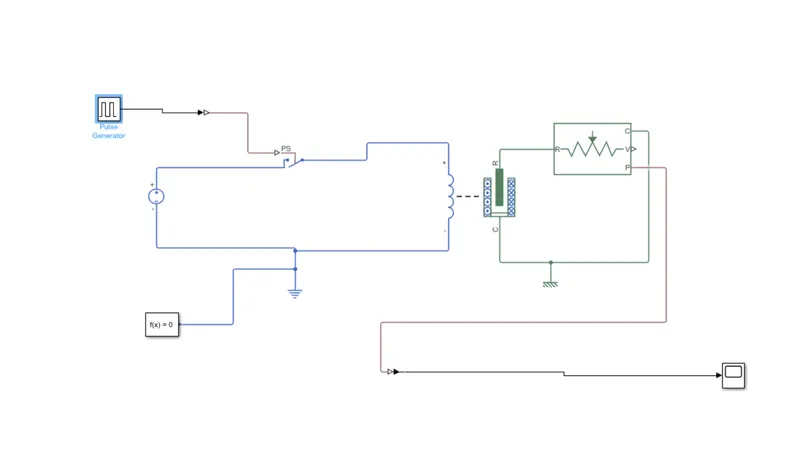
The pulse generator is set to be delay by 2 sec
The results are shown in the scope below
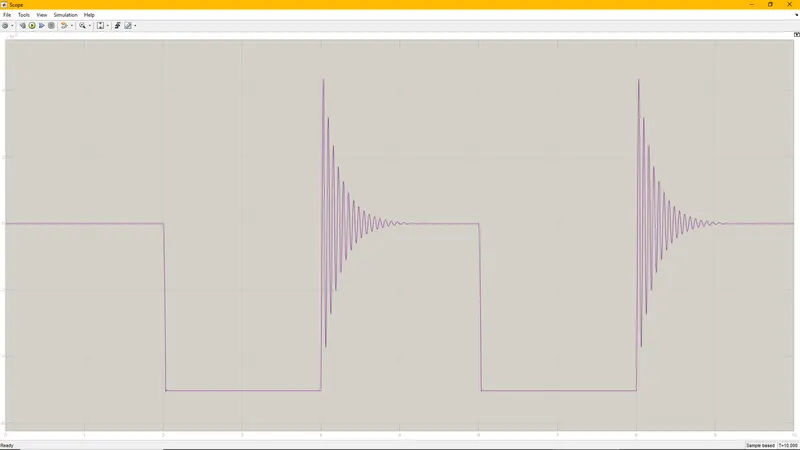
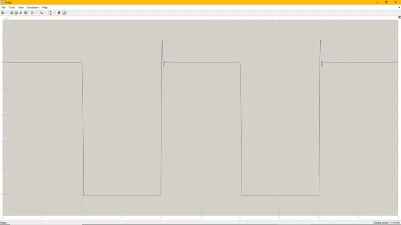
The above result is simulated for damping value of 0.5. As the damping value increases the output result is getting smooth.
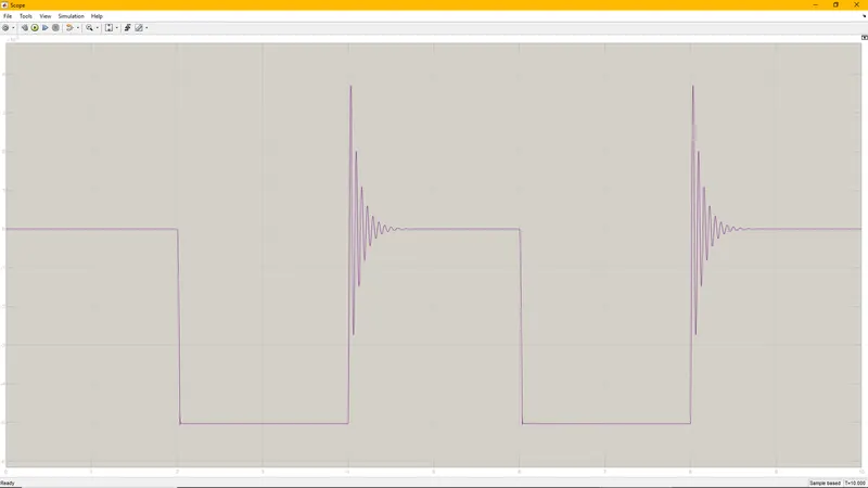
For the damping value of 5
2. Use a thermistor to sense the temperature of a heater & turn on or turn off the fan as per the below conditions:
Temperature source: 20 °C from 0 to 10 seconds, 27 °C from 10 to 30 seconds, 23 °C from 30 to 50 seconds
Fan conditions: ON if the temperature above 25 °C, OFF otherwise
ANS:
THERMISTOR:: It is a temperture sensing device. It is a resistance that depends with temperature. Generally resistors values change with temperature. Thermistor is a device that is very senstive with temperature.
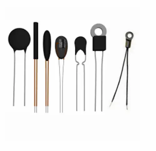
In this model we are using thermistor to sense the temperature of the heater.
The following blocks are required in matlab simulink
- Dc source
- thermistor
- temperature sensor
- switch
- scope
- ps to simulink converters
- display
- resistor
- thermal resistance
- electrical resistance
- voltage sensor
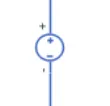
DC SOURCE of 100 v is pre defined as the voltage source
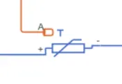
A THERMISTOR is a resistance that is very sensitive with temperature
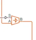
A TEMPERATURE SENSOR that sense temperature and provides the input to thermistor. where A is a common thernal refrence and B is the output that is feeded to thermistor A.
A signal builder block that builds the required input to the temperature sensor
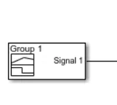
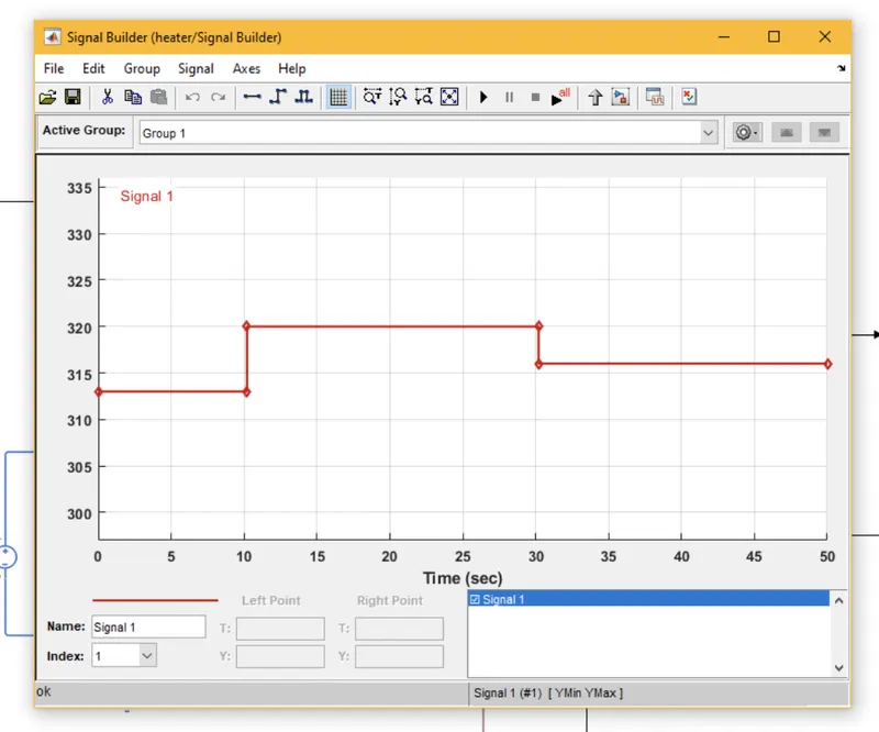
In the above model temperature is given in celsis and is converted into kelvins by adding 293 k to the O c.
A solver configuration block is added to run the physical systems
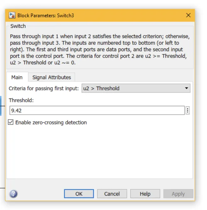
To control the fan switch after temperature reaches to 25 c a switch and a voltage sensor is used to find the voltgae across the resistor when temperature reaches to 25 deg cel is 9.42v.
A switch is used to control the ON and OFF of the fan .
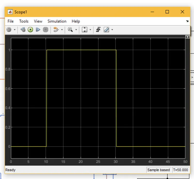
The final output of the model is shown below
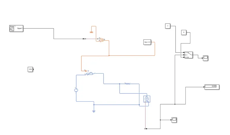
The scope 1 results shows that switch output. When temperature crosses 25 deg that output is shown as 1 otherwise zero.
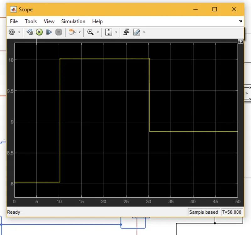
The below scope results shows the voltage across the resistor when temperature changes.