Week -2
AIM :
1. To Make a Simulink model of Doorbell using solenoid block.
2.To Make a Model To Use a thermistor to sense the temperature of a heater & turn on or turn off the fan.
OBJECTIVE :
- Make a Simulink model of Doorbell using solenoid block with the following details:
In the given arrangement, when the switch is closed the electromagnet receives electrical power from the battery and pulls the metal arm to hit the bell producing sound.
Creating a situation where the switch is closed for 2 seconds and then released. To Observe the physical movement of the plunger.
With Assuming remaining parameters.
2. Use a thermistor to sense the temperature of a heater & turn on or turn off the fan as per the below conditions:
Temperature source: 20 °C from 0 to 10 seconds, 27 °C from 10 to 30 seconds, 23 °C from 30 to 50 seconds
Fan conditions: ON if the temperature above 25 °C, OFF otherwise.
THEORY :
Schematic Diagram of Door Bell
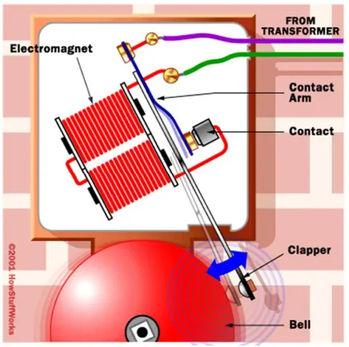
Fig :A standard bell ringer design works just like a buzzer except the contact arm is attached to a long clapper that hits a metal bell.
Introduction to How Doorbells Work With Solenoid
Doorbells are one of those everyday devices we take for granted. On the surface, they couldn't be simpler: You press a button, which completes a circuit, which turns on some sort of noisemaker. In a world full of computers, cars and televisions, that doesn't seem so impressive.
But when you take off the cover and see what's going on, conventional doorbells are one of the coolest machines around, precisely because of their simplicity. Doorbells put the basic principle of electromagnetism to work in remarkable, innovative ways.
A chime doorbell uses a specialized sort of electromagnet called a solenoid. A solenoid is just a electromagnet where the coiled wire surrounds a metal piston. The piston contains magnetically conductive metal, so it can be moved backward or forward by the electromagnetic field. Press the button in the Model of DoorBell Using SOLENOID Block diagram below to see how this works.
The common chime design uses a solenoid to hit two tone bars in sequence. Press the button to see how this system works.
In this design, the solenoid piston consists of an iron core mounted to a non-magnetic metal bar.When there is no power to the electromagnet, a spring pushes the piston to the left, and the iron core extends outside of the wire coil. When you turn the electromagnet on (by pressing the doorbell button), the iron core is drawn to the magnetic field, so it slides into the center of the coiled wire. And when the the switch is closed the electromagnet receives electrical power from the battery and pulls the metal arm to hit the bell producing sound.
SIMULINK MODEL :
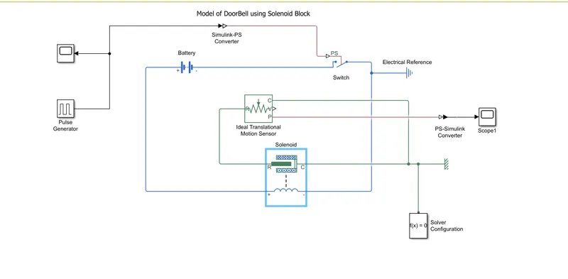
BLOCKS USED :
- Pulse Generator -To Generate time signals to control the switch operation
- Scope - For viewing the graph of the signals
- Simulink-PS- To convert simulink environment to Real time environment
- Switch - The block represents a switch controlled by an external physical signal. If the external physical signal PS is greater than the threshold, then the switch is closed, otherwise the switch is open.
- Battery - Power source for the bell to ring
- Electrical & Mechanical References - Denoting that all the electrical and mechanical blocks are grounded properly
- Solenoid block -To generate magnetic field to attract the hammer to ring the bell
- Ideal Transitional Motion Sensor - This block measures velocity or displacement in a mechanical translational network.
- PS-Simulink- To convert Real time environment to simulink environment.
EXPLANATION :
1.In the pulse generator signals are generated for every 2 sec to control the switch to ring the bell.
2.The generated signals are plotted and then converted to real time environment.
3.Battery is used to give current source to the circuit as soon as ps switch gets closed.
4.Then according to the signal switch acts to control the flow of current to solenoid.
5. when the current is passed to the solenoid it generates magnetic field to attract the iron armature.
6. From the Solenoid the motion is sensed using the Ideal Motion sensor then the signal are converted to the simulink environment to record the motion of the hammer.
7. Electrical and Mechanical referances is used to give a particular fixed or referance poistion in respect to the other points been operated.
OUTPUT :
The signal is generated using the pulse generator for every 2 second to control the switch to ring the bell.
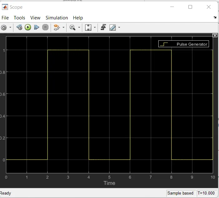
Fig : The above plot repesent the signal geneted for every 2 second.
CONCLUSION FOR DOOR BELL :
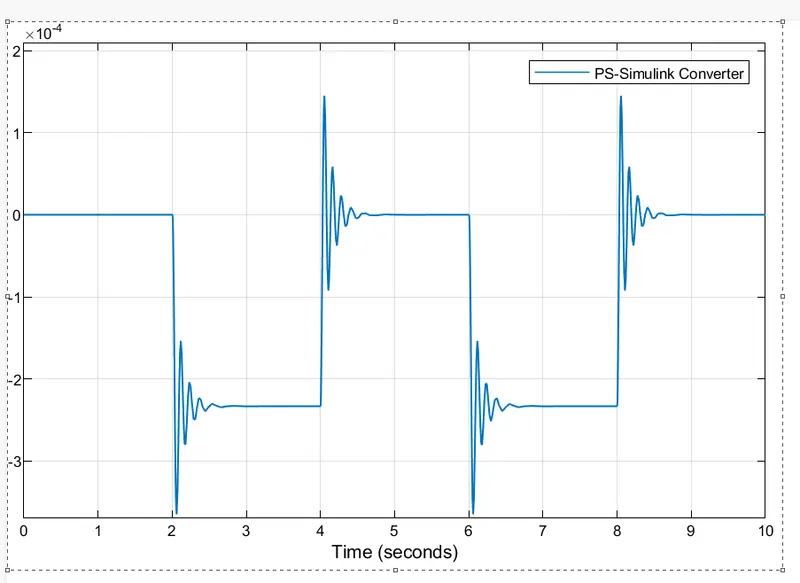
Giving the input as time period for 2 seconds in the pulse generator to open and close the switch.when the switch is closed the solenoid block recevies electrical power from the battery and plunger moves from port R to port C to hit the bell and produces sound.
Physical movement of the plunger is observed by using the ideal translational motion sensor & physical output is converted into simulink output model is displayed in the scope .By reducing the spring constant value and increasing the damping value vibration is reduced.
2. Use a thermistor to sense the temperature of a heater & turn on or turn off the fan as per the below conditions:
Temperature source: 20 °C from 0 to 10 seconds, 27 °C from 10 to 30 seconds, 23 °C from 30 to 50 seconds
Fan conditions: ON if the temperature above 25 °C, OFF otherwise.
THEORY :
THERMISTOR
A thermistor (or thermal resistor ) is defined as a type of resistor whose electrical resistance varies with changes in temperature. Although all resistors’ resistance will fluctuate slightly with temperature, a thermistor is particularly sensitive to temperature changes.
SIMULINK MODEL :
BLOCKS USED :
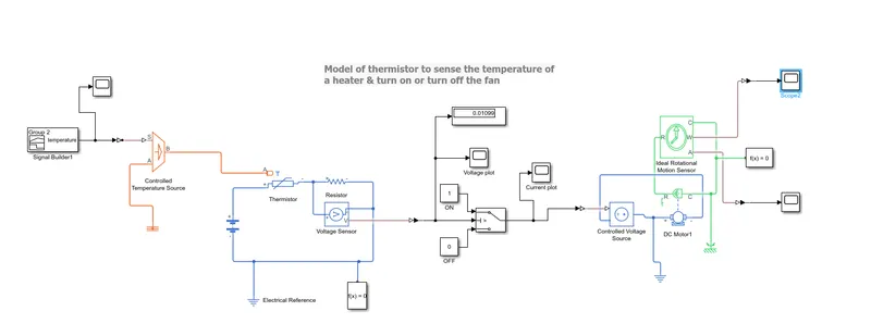
- Signal Builder- Signal Builder window, create signals and define the output waveforms
- Simulink PS-convertor - Coverts Simulink signal to the physical signal.
- Controlled Temperature Source - Provide a temperature physical output based on the condition given to port S .
- Thermistor - Thermistor block which shows us the NTC thermistor reation between temperature and resistance.
- Resistor - Resistor which provides the opposing nature of current in a circuit.
- Voltage Sensor - This is used t measure the voltage or potential difference across any electrical components and it should connect in parallel only.
- PS Simulink Convertor- Convert physical signal to the respective simulink signal.
- Constant - Provides a constant output value here the constant 1 is defined as ON and constant 0 is OFF.
- Switch- Pass through input 1 when input 2 satisfies the selected criterion; otherwise, pass through input 3. The inputs are numbered top to bottom (or left to right). The first and third input ports are data ports, and the second input port is the control port.
- Display- To view the threshold value of the voltage
- Controlled Voltage Source - To seperate the voltage into (+ & -) ions.
- D C Motor - To run at controlled voltage
- Ideal Rotational Motion Sensor - To sense the working of DC motor.
- Scope - For viewing the graph of the signal.
- Electrical & Mechanical Referance - Denoting that all the electrical & mechanical blocks are grounded properly.
EXPLANATION :
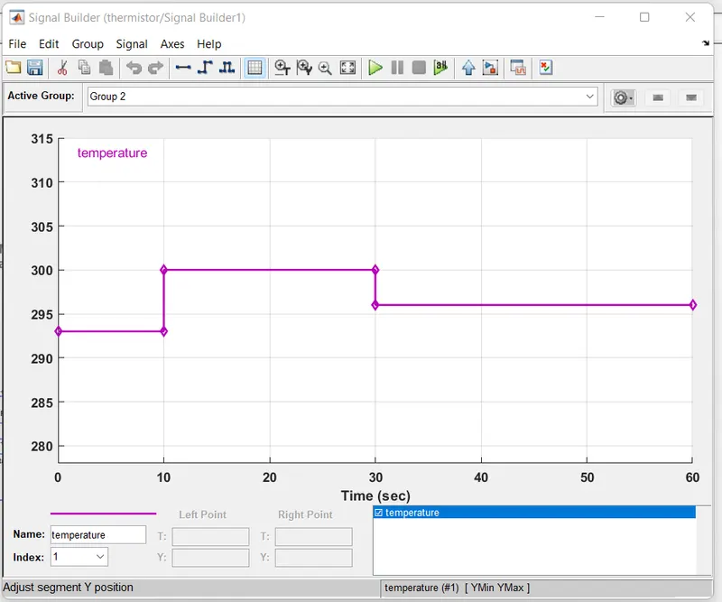
1.The signal builder generates the time interval with various temperature as a source of heater.
Temperature source:
20 °C from 0 to 10 seconds,
27 °C from 10 to 30 seconds,
23 °C from 30 to 50 seconds
Fan conditions: ON if the temperature above 25 °C, OFF otherwise.
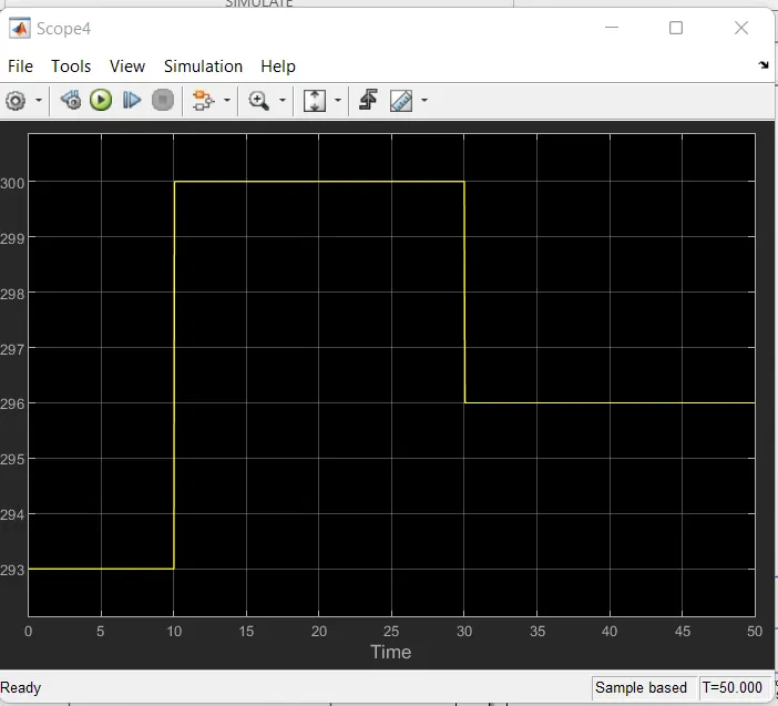
2.The temperature data is passed to the thermistor to sense and generate the resistance value accordingly
3.As the resistance R varies accordingly to the current I,voltage across it being sensed using voltmeter (voltage sensor)
4.The voltage is inputted to the (threshold controlled) switch for turning ON the motor(Fan) with a threshold value of 0.01099.
5.Then the perticular value (T=27)the DC Motor is turned ON.
6.Using the Ideal Rotational Motion Sensor the activities of DC motor is obtained for plotting the velocity and angular displacement plots.
OUTPUT/RESULT :
Voltage Sensor Output Plot
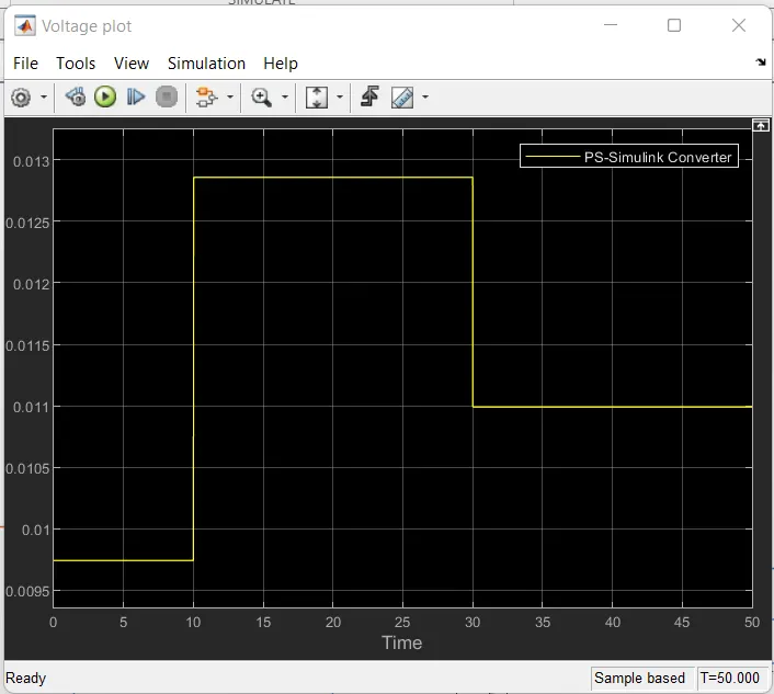
From this plot we can conclude that the voltage is generated according to the temperature input with respect to time. so the maximum voltage at T=27 degree celcius is 0.012859 V.
Switch plot
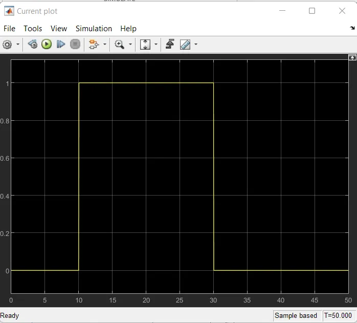
From this plot we can conclude that the voltage is obtained for (10-30 S) at T=27 Degree celcius to turn ON the motor . The threshold value used is 0.01099.
Velocity plot
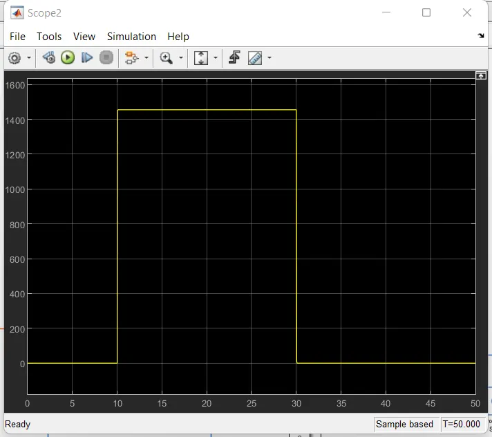
Fom the above plot we can conclude that the Fan (DC Motor) was turned ON when the temperature exceeds T=25 degree celcius.Here out of three inputs T=27 degree celcius is where it exceeds T=25 degree celcius so the fan will be turned ON for the time 10-30 sec.
Angular Displacement
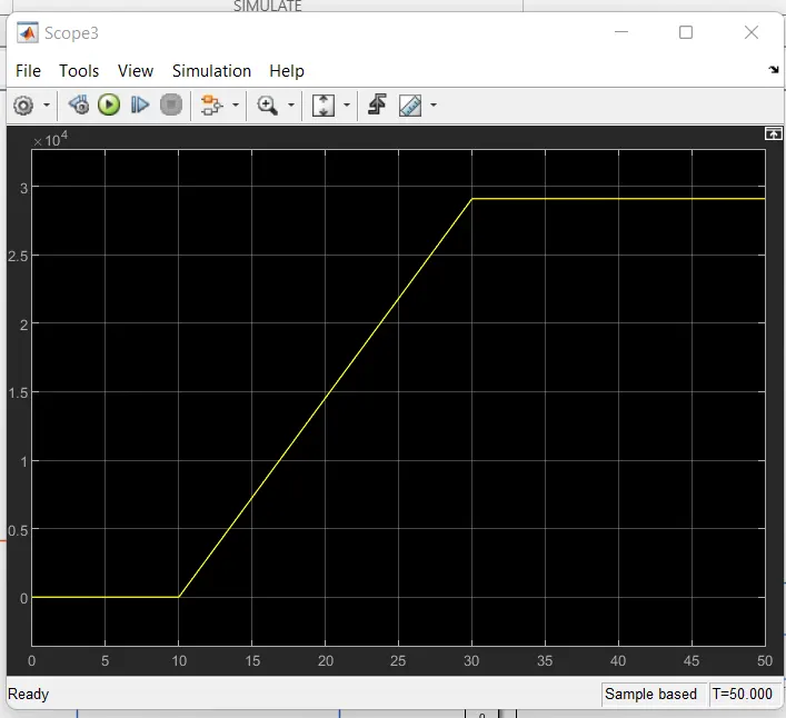
CONCLUSION :It can be concluded that both the studies were plotted with observed output
1. A situation is created where the switch is closed for 2 seconds and then released. to Observe the physical movement of the plunger. When a doorbell is rang a deflection was observed.
2.Fan temperature was sensed by the thermistor in the Heater model.
Simulink Model :