Week 2- 2R Robotic Arm Challenge
Aim:
MATLAB program for simulate the forward kinematics of a 2R Robotic arm.
INTRODUCTION:
• In Automobile industries & aviation industries all the processes like welding & painting are done by robots. So, at the design stage of robots designers need to know the workspace of the robot for particular operation, so by software like MATLAB designers can easily know range of robot by inserting different size of robotic arm and different angles of robotic arm with reference surface.
• In Robotic field kinematics is a very important part, by which we can program & simulate how a robot is going to move. By simulation we can figure out the workspace of the Robot for design.
EQUATION:
We will take a simple Robotic arm with two links for our programming. As per below image L1 (1.5m) & L2 (0.5 m) are two links of the arm which makes Ɵ1 & Ɵ2 angle with the horizontal axis respectively.
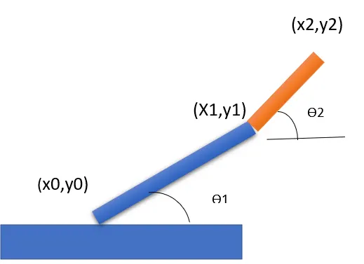
Equation for calculate staring & ending co-ordinates of link.
• Co-ordinates of Link1
Starting point=[x0, y0] = [0, 0]
Ending Point = [x1, y1] = [L1 cosdƟ1, L1 sindƟ1]
• Co-ordinates of Link2
Starting point=[x1,y1] = [L1cosdƟ1, L1 sindƟ1]
Ending Point = [x2, y2] = [x1+ L2 cosdƟ2, y1 + L2 sindƟ2]
OBJECTIVE:
• We will take various values of Ɵ1 & Ɵ2 range from 0 to 90 and by all different combinations of those values plots will be created, and at the end by combining all the plots together to make a animation.
PROGRAM:
clear all
close all
clc

%input
l1=1.5;
l2=0.5;
theta1=linspace(0,90,10);
theta2=linspace(0,90,10);

ct=1;
for i=1:length(theta1)
    THETA1=theta1(i);
    for j=1:length(theta2)
    THETA2=theta2(j);

    x0=0;
    y0=0;

    x1=l1*cosd(THETA1);
    y1=l1*sind(THETA1);

    x2=x1+l2*cosd(THETA2);
    y2=y1+l2*sind(THETA2);

    %plotting

    plot([x0 x1],[y0 y1],[x1 x2],[y1 y2],'linewidth',3);
    grid on;
     axis([-0.5 2.5 0 2.5]);
    pause(0.03)
    M(ct)=getframe(gcf);
    ct=ct+1;
    end
end

movie(M)
videofile=VideoWriter('forward_kinematics.AVI','Uncompressed AVI');
open(videofile)
writeVideo(videofile,M)
close(videofile)
Firstly provide input
Length of the links
L1 = 1.5
L2 = 0.5
Angle of both links with the horizontal axis
theta1 = =linspace(0,90,10)
theta2 =linspace(0,90,10)
By using linspace command 10 values for theta will be calculated, which is starting from 0 to 90 degrees.
Plot can be generated for different values of theta by manually changing the values but it is time consuming work, to make it automatic we will use forloop function.
for i=1:length(theta1)
Value of 'i' will change from 1 to the length (theta1), length (theta1) is nothing but all the 10 theta values between 0 to 90, which is generated by linspace command
THETA1 = theta1(i)
THETA1 is a variable, where thata1 is a array, 'i' is loop counter which determine how many times forloop get executed.
For each value of theta1, theta2 will change 10 positions, for that second forloop is required.
for j=1:length(theta2) THETA2 = theta2(j)
Then we have equation for calculate values of point
x0=0;
yo = 0;
x1 = l1*cosd(THETA1);
y1=l1*sind (THETA1);
x2 = x1 + l2*cosd(THETA2);
y2 = y1 + l2*sind(THETA2);
plot([x0 x1],[y0 y1], [x1 x2],[y1 y2], 'linewidth",3);
By plot command plot will be generated, in which linewidth and color is specified for particular link
axis ([-0.5 2.5 0.5 2.5])
This command is used for fixing the work area in the graph.
pause(0.3)
grid on
grid Used to turn on grid in plot.
ct = ct + 1
increment forloop execution.
VideoWrite('forward_kinematic','uncompressed AVI')
command used to convert animation to avi video file.
Error:
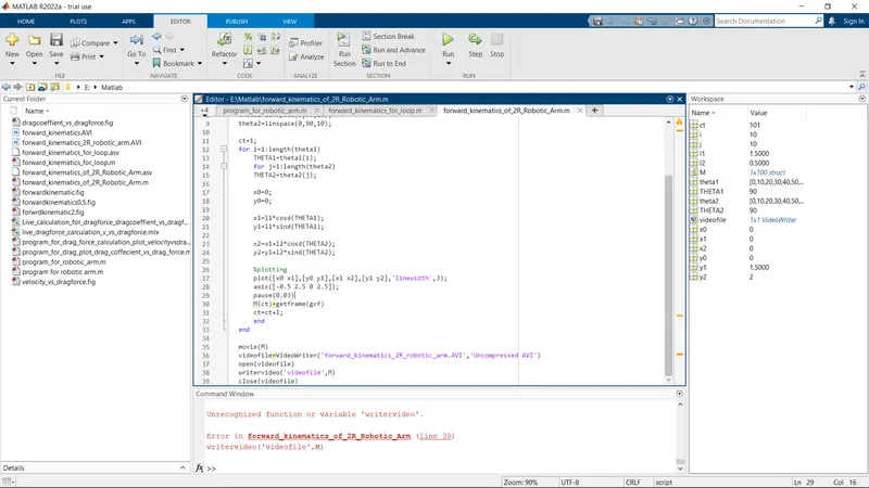
I had type ( writevideo('videofile',M)) videofile in single quote, beacause of that error is occure.
Output:
- After generating plots based on theta1 and theta2 values, all plot should be combine together to generate gif file.
- Videofile=VideoWrite('forward_kinematics','Uncompressed AVI') this command convert gif file to video file.
Output of Program:
Workspace were robot will operate.
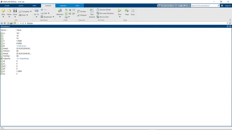
after generating animation file it is uploaded on google drive and link is given below.
https://drive.google.com/file/d/12HdZl7kKOHZu2lo371ufuXnncSnSP7hi/view?usp=sharing
Conclusion:
- The workspace of the robotic arm which is our main purpose and we understand from animation that was genearated from plot.
- By changing parameter of the links different combinations are possible and by plotting these graph of different combinations robot design can be done.