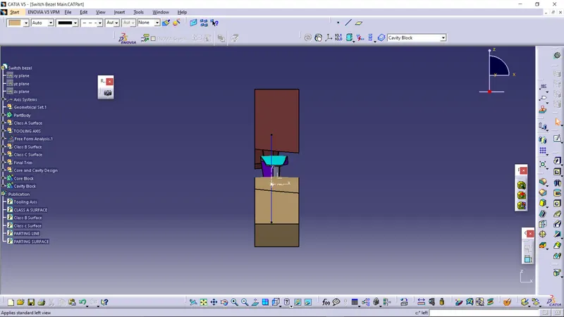
Week 8 - Challenge 6 - Core & Cavity Design
- Aim: Create the Core and cavity blocks for the switch bezel designed in the earlier challenge.
- Report:
I had exatract the surface from the Class A surface and then create a point on the surface and through that point create a line. create a intersection curve with Class A surface with plane and from that two parallel surface draw a line and from that line i had created the tooling axis by bisecting that two lines.
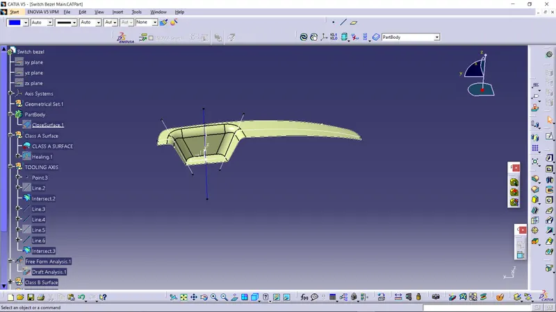
Tooling Axis : Tooling Axis is blue colour line.
Class A Surface : class A surface is given as input .
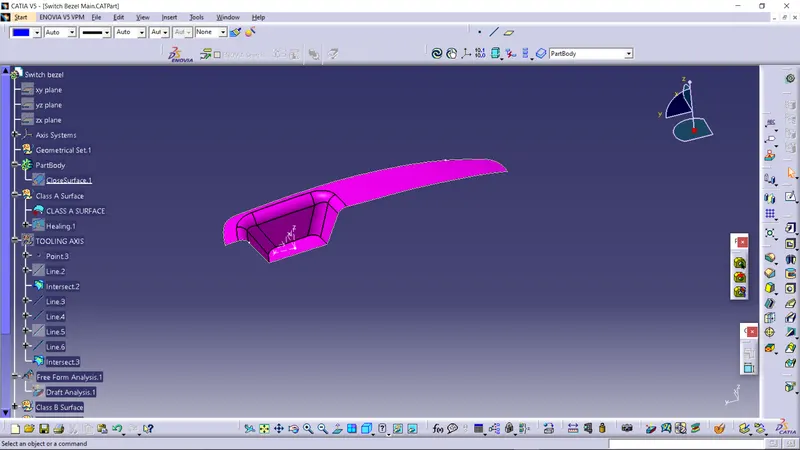
Class B Surface: I had created the class b Surface from the class A surface by extracting the surface then untrimming and extrapolation and trimed with other surfaces. the thickness of the final solid part is 2.5mm bacause that i had offseted the class B Surface from class A surface by 2.5mm.
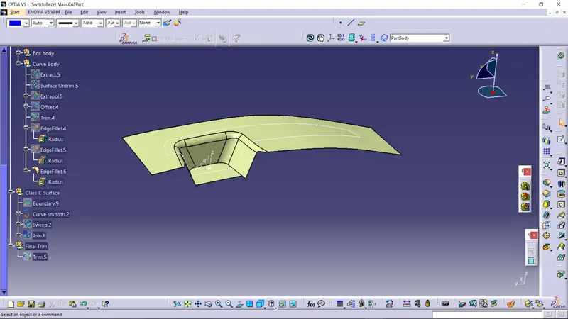
class b Surface is same as of class A surface but it offseted from class A . class B surface is alway behind the class A surface.
Class C Surface : when Drafting suface is parallel to tooling axis then we given draft angle of 0 to 3 degree, but when drafting surface or class surface is perpendicular to the tooling axis then we take sweep angle as 90 degree.
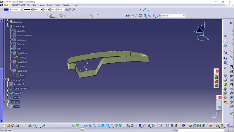
Class C surface join the Class A surface and the Class B surface size of the class C is thickness of the part.
Final Closed Surface of the Switch bezel is created by joining the Class A surface and Class C surface and that joined body trim with the Class B surface and created the final closed body.
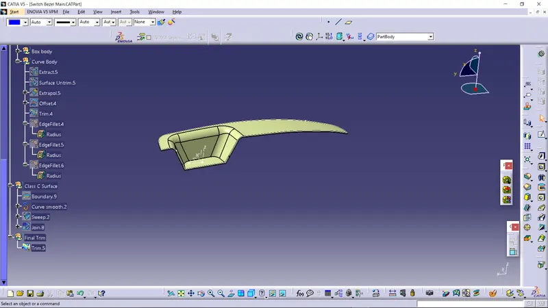
Solid Part: I had created the solid body by using close surface command in part design from that closed body.
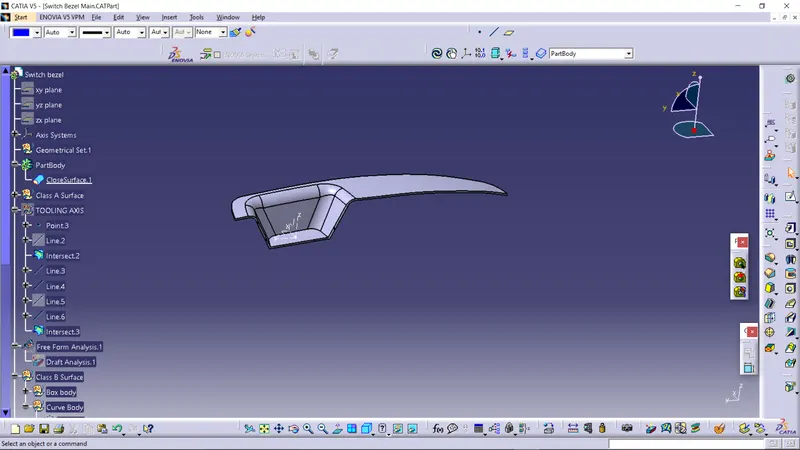
Draft Analysis :
Draft Analysis of Class A surface:
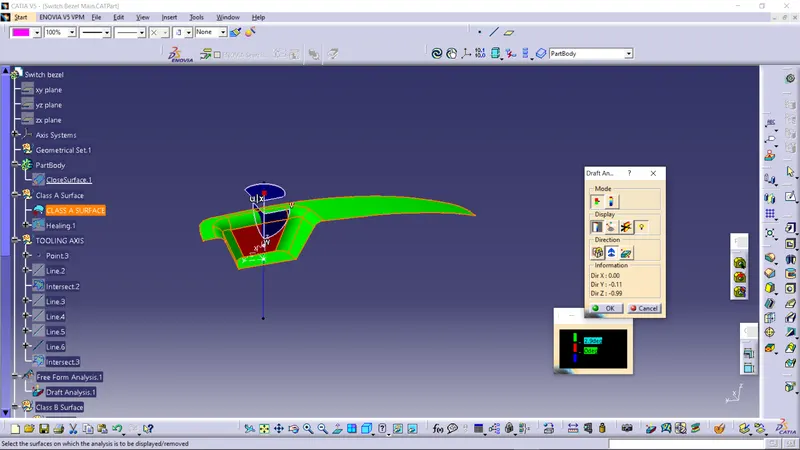
i had done the draft analysis of the class A surface with draft angle of 2.9 degree. Class A surface has problem that class A surface is send back to the class A designer.
Draft Analysis of Coin holder plastic component:
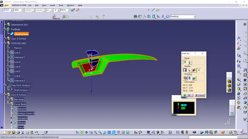
I had done the draft analysis of coin holder it is given as below. The coin holder is easily ejected from mould at draft angle of 2.9 degree. i had change the value of draft angle from 0 to 3 degree it gives same result and it get easily ejected from mould.
Core And Cavity Design:
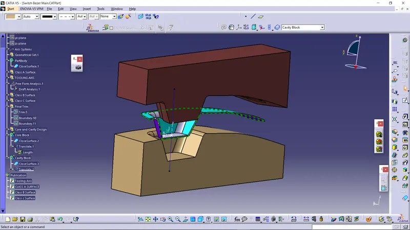
PARTING SURFACE
- Generally injection mold has two major components : the movable half and the fixed half, during the injecction molding process, these two halves are pressed tightly from a sealed hollow to avoid the melt flow leakage and maintain certain holding pressure, the pressed surface are called parting surface , usually parting surface are the biggest projection outline of the part.
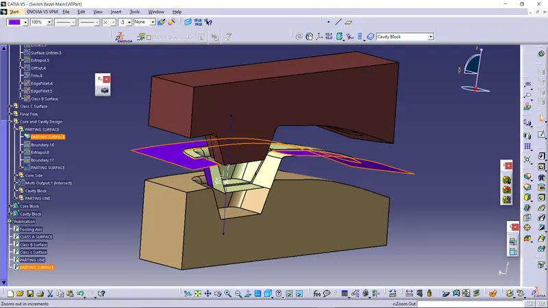
Parting surface is coloured as purple colour.
PARTING LINE
- A parting line is an inevitable part of injection molded products.
- It is the line of separation between where two halves of a mold meet.
- It manifests itself on injection molded parts as a line that runs the entire perimeter of the part.
- In most parts, it is just a line that runs straight down the middle.
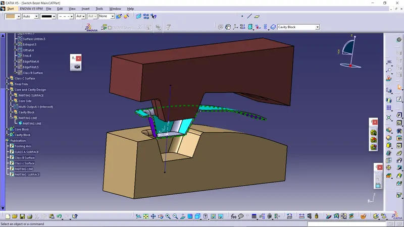
Parting line is coloured by dark green colour and dashed line.
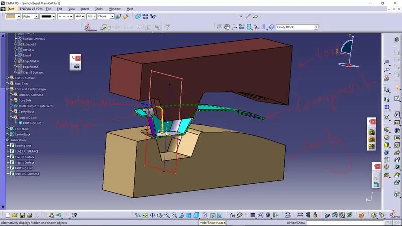
Core Block: Highlighted by brown colour.
Cavity Block : Highlighted by beige colour.
Parting surface: Highlighted by blue dashed line.
Parting line: Highlighted by dark green dashed line.
Publication:
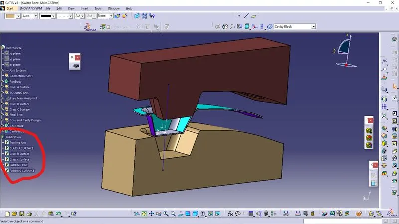
Isometric View:
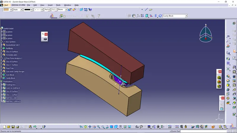
Top View:
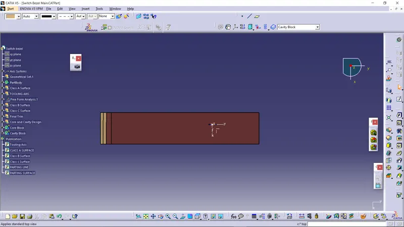
Front View:
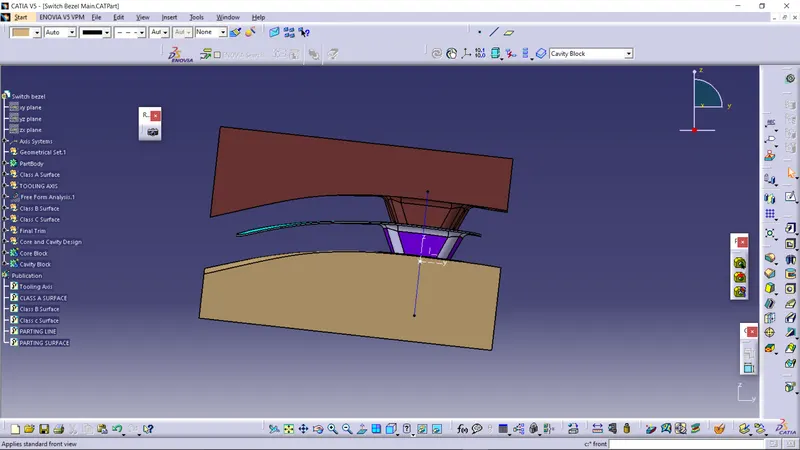
Right View:
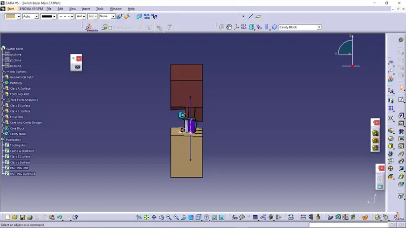
Left View: