Week 9 - Project 1 - Door Trim Lower with Engineering Features
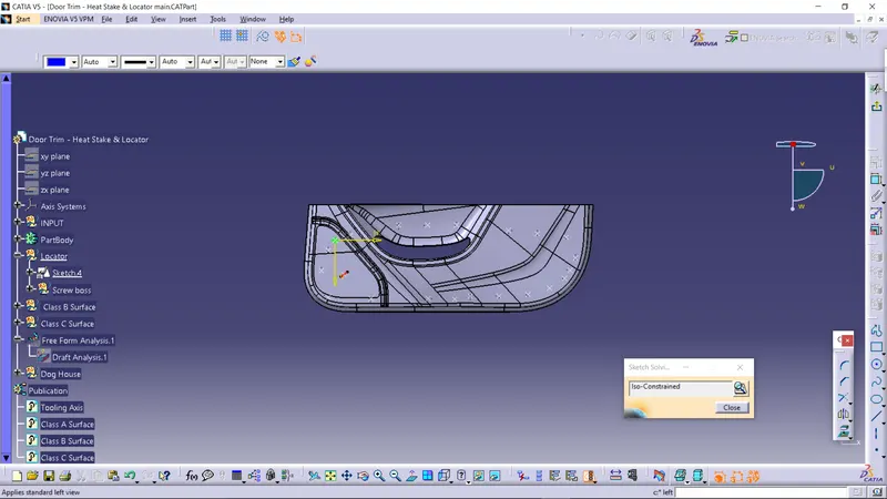
- Aim: Create the Door Trim Lower Plastic component through the given Class-A surface. To begin with, the tooling axis for the given Class-A Surface should be created meeting the requirements of the draft angle and at the end perform the Draft analysis on the model.
- Report:
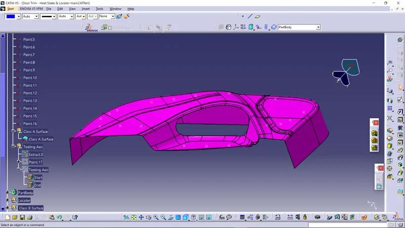
I had exatract the surface from the Class A surface and then create a point on the surface and through that point create a line normal to surface.
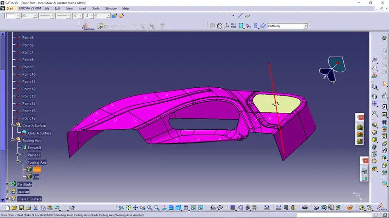
Tooling Axis is red colour line.
Class A Surface : class A surface is given as input.
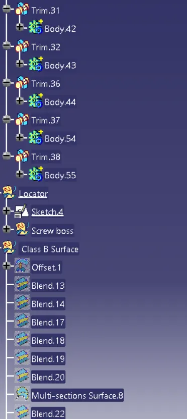
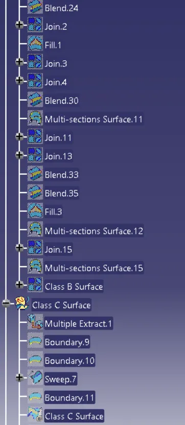
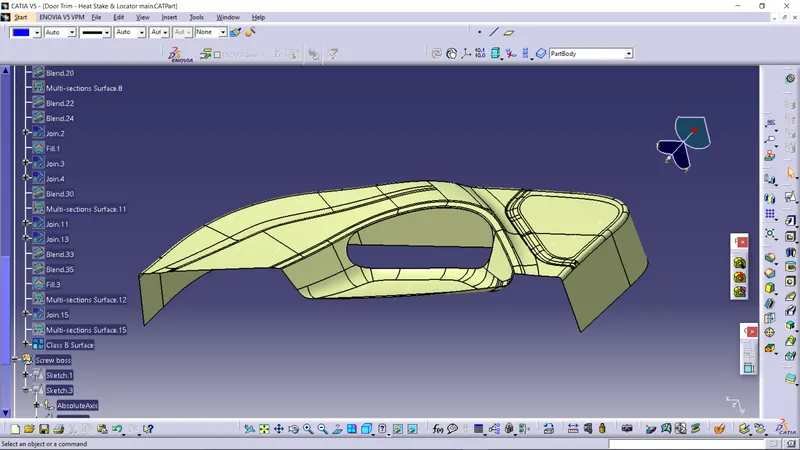
Class B Surface: I had created the class b Surface from the class A surface by extracting the surface then untrimming and extrapolation and trimed with other surfaces. the thickness of the final solid part is 2.5mm bacause that i had offseted the class B Surface from class A surface by 2.5mm.
Class B Surface: class b Surface is same as of class A surface but it offseted from class A . class B surface is alway behind the class A surface.
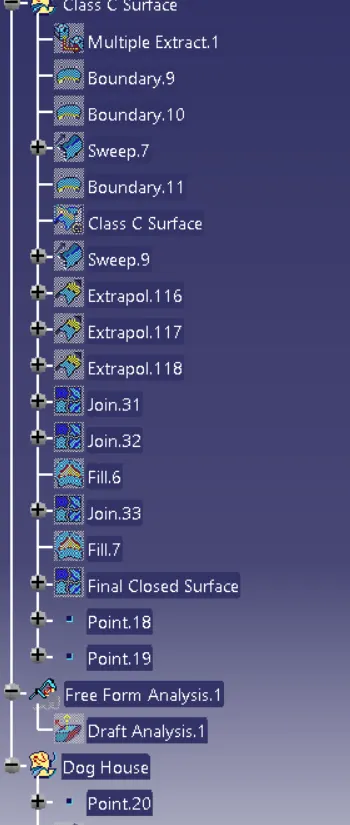
Class C Surface : when Drafting suface is parallel to tooling axis then we given draft angle of 0 to 3 degree, but when drafting surface or class C surface is perpendicular to the tooling axis then we take sweep angle as 90 degree.
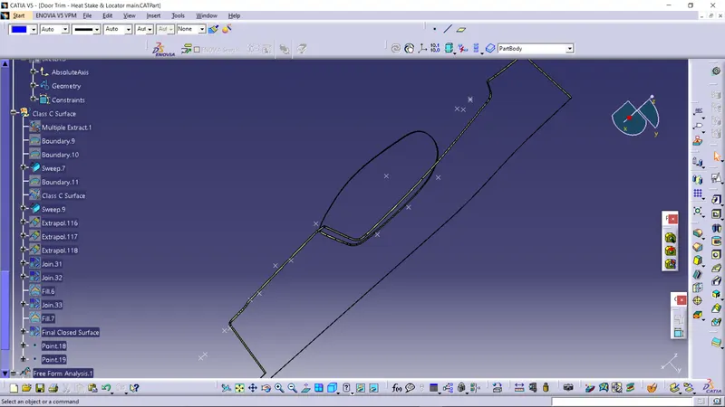
Class C surface join the Class A surface and the Class B surface size of the class C is thickness of the part.
Final Closed Surface of the coin holder is created by joining the Class A surface and Class C surface and that joined body trim with the Class B surface and created the final closed body.
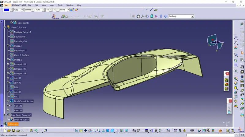
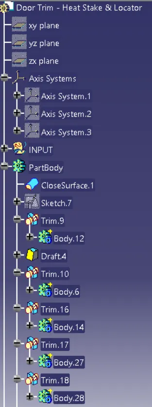
Solid part : I had created the solid body by using close surface command in part design from that closed body.
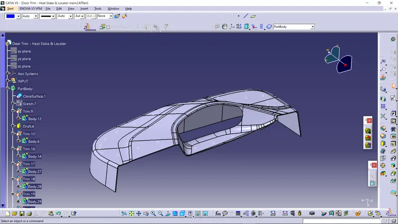
Draft Analysis :
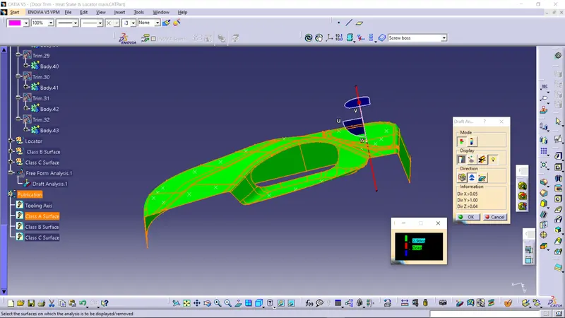
Draft Analysis of Class A surface:
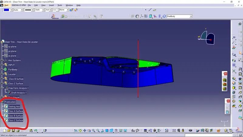
I had done the draft analysis of the class A surface with draft angle of 2.9 degree.
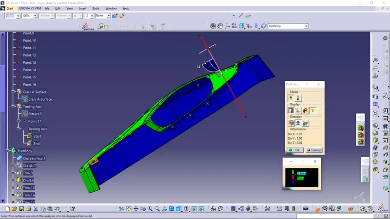
Draft Analysis of Solid Part:
I had done the draft analysis of the solid part with draft angle of 2.9 degree but their is red surface is due to zero degree draft angle it get eliminated when change draft angle to 2 degree and then part get easily ejected from the mould.
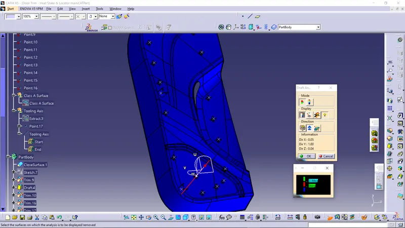
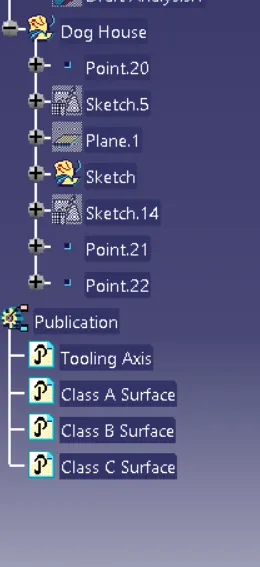
Publication:
Engineering Features:
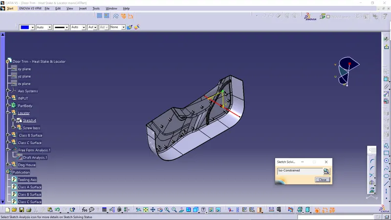
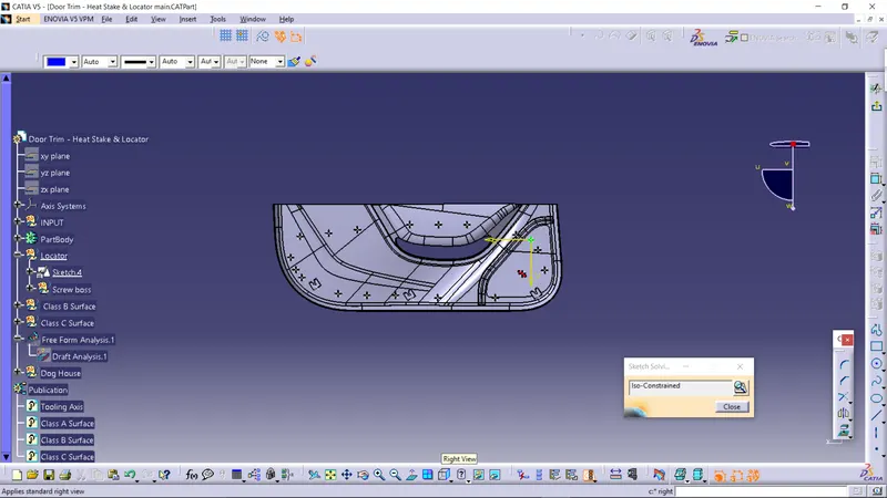
Two 4 way locator are their to locate the component, other are screw bosses and dog house to provide support to other engineering features.
Isometric view:
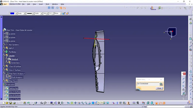
Top View:
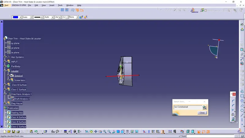
Front View:
Right View:
Left View: