Week -2
AIM:
1. To design a Simulink model of a Doorbell using solenoid
Conditions applied:
the switch is closed for 2 seconds and then released. Observe the physical movement of the plunger.
2. To Use a thermistor to sense the temperature of a heater & turn ON or turn OFF the fan as per the given conditions:
Temperature source:
20 °C from 0 to 10 seconds,
27 °C from 10 to 30 seconds,
23 °C from 30 to 50 seconds
Fan conditions: ON if the temperature is above 25 °C, OFF otherwise
1. To design a Simulink model of a Doorbell using solenoid:
Principle of working of a Doorbell:
The electric doorbell is a device having both mechanical and electrical components which produce sound on pressing the switch.
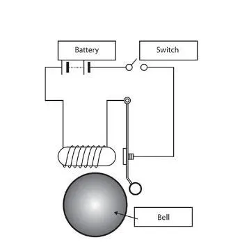
The principle is that when the switch is pressed, the circuit energizes which allows the current from the battery to flow through the circuit. While passing through the solenoid it generates an electromagnetic field in the desired space which allows the plunger the move due to which it strikes the bell and produces sound.
SIMULATION OF DOORBELL CONSISTS OF CONFIGURATION OF VARIOUS BLOCKS OF MECHANICAL AND ELECTRICAL COMPONENTS WHICH IS AS FOLLOWS:
1. Pulse Generator:
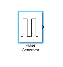
- This block generates square wave pulses at regular intervals. The parameters are Amplitude, Pulse Width, Period, and Phase delay, which determine the shape of the output waveform.
- By differing the Amplitude, Pulse Width, Period, and Phase delay the different square wave pulses are generated. In time-based mode, it computes the block output only at times when the output changes.
- This approach results in fewer computations for the block output over the simulation period.
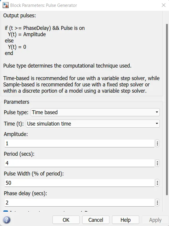
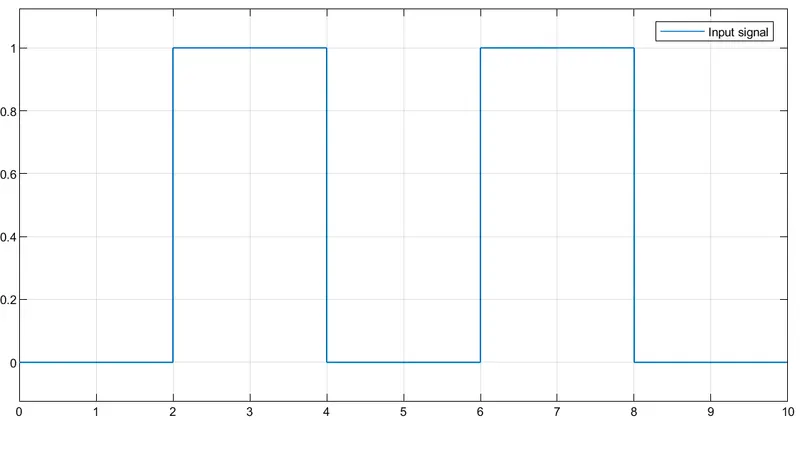
- To observe the physical movement of the plunger, the switch is closed for 2 seconds and then released. For that, the delay time was assigned as 2 seconds. The period and pulse width is assigned based on the time intervals and the simulation time is assigned as 10 seconds.
2. Simulink to PS converter
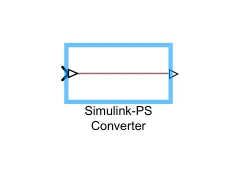
The Simulink signals are converted into physical signals by using Simulink -PS converter.
3. Switch:
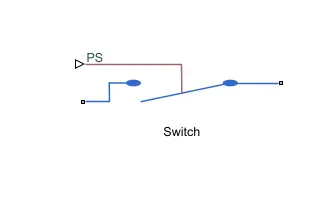
The signals are connected to the switch system. The Switch block models a switch controlled by an external physical signal. The generated pulse signals are converted and connected to the switch block. If the external physical signal PS is greater than the value specified in the Threshold parameter, then the switch is closed, otherwise, the switch is open.
4. Battery
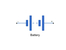
The switch is then connected to the battery which is the power source. when the switch is closed the electromagnet receives electrical power from the battery to energize the circuit.
5. Solver Configuration
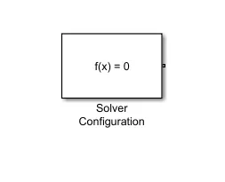
The Solver Configuration block specifies the solver parameters that the model needs before beginning simulation. Each topologically distinct Simscape block diagram requires exactly one Solver Configuration block to be connected to it.
6. Electrical Reference
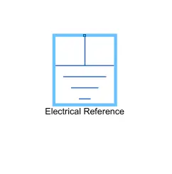
The Electrical reference block represents an electrical ground. Electrical conserving ports of all the blocks that are directly connected to the ground must be connected to an Electrical Reference block.
7. Solenoid
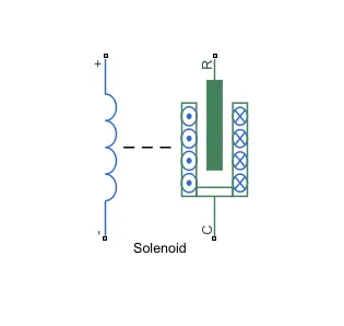
The solenoid block acts as an Electro-mechanical device in which the electrical signals are been converted into an equivalent mechanical signal.
8. Ideal Translational Motion Sensor
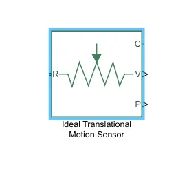
The ideal Translational Motion Sensor block represents a device that converts an across variable measured between two mechanical translational nodes into a control signal proportional to velocity or position.
9. Mechanical Reference
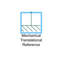
The Mechanical translational reference block represents a reference point, or frame, for all mechanical translational ports. All translational ports that are rigidly clamped to the frame (ground) must be connected to a Mechanical Translational Reference block.
10. PS to Simulink Converter
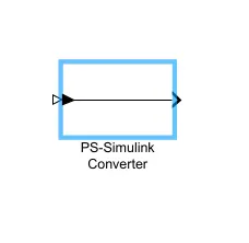
Convert physical signal into Simulink output signal. The damped signal from the motion sensor is then converted into a Simulink signal which shows the plunger position of the doorbell through the scope.
11. scope
The Scope block displays time-domain signals and the scope displays simulation results for attached input signals. From the output of the delay signal to 2 seconds the plunger positions are been observed.
DESIGN OF DOORBELL SIMULATION IN SIMULINK:
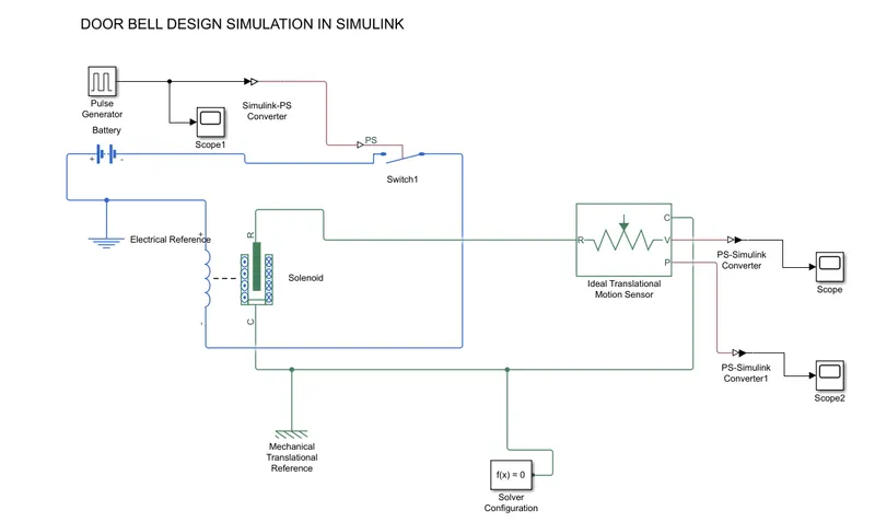
MODEL LINK:
WORKING:
The simulation time is to be assigned as 10 seconds.
From that, the equations from the blocks are computed, and signals and states are solved and updated in the scope where the position of the plunger is determined.
The pulse is generated with a delay time of 2 seconds then the signals are converted into physical signals and connected to the switch block.
In the switch block if the threshold value is static find the switch turns on and the electrical flow takes place.
The solenoid block act as an electromechanical device in which the signals are been monitored by an idea translational motion sensor. Then the signals are converted into Simulink signals to visualize the damped plunger position.
INPUT SIGNAL PLOT:
OUTPUT PLOTS:
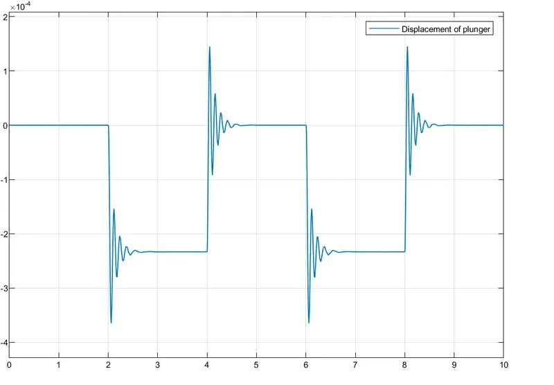
1. Displacement of plunger:
2. Velocity of the plunger
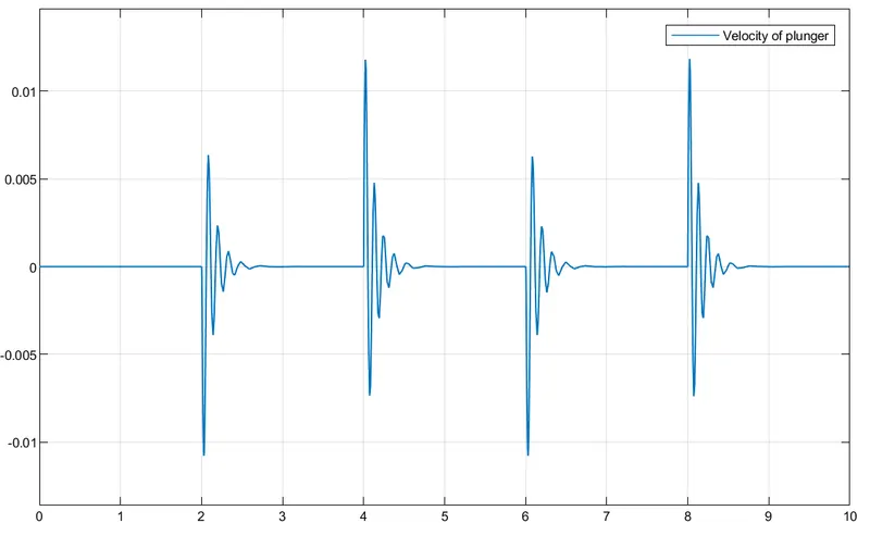
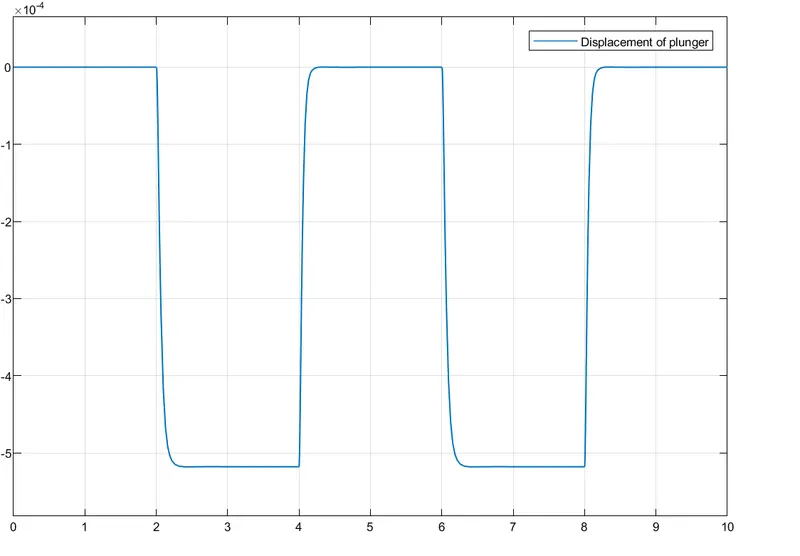
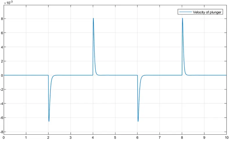
From the above plots, it is evident that there is a disturbance in the signal. So, to minimize the disturbances we can reduce the stiffness of the spring 'K' to 100 and the damping co-efficient 'C' to 5. Therefore, we get the below output plots.
Displacement of plunger:
The velocity of the plunger:
II. MODELLING OF THERMISTOR CONTROLLED FAN:
AIM: To design a Simulink model of a thermistor which is used to sense the temperature of a heater to turn ON or OFF a fan.
Conditions applied;
Temperature source:
20 °C from 0 to 10 seconds,
27 °C from 10 to 30 seconds,
23 °C from 30 to 50 seconds
Fan conditions: ON if the temperature is above 25 °C, OFF otherwise
Introduction:
Thermistor- It is a combination of "thermal" and "resistor".
The circuit symbol of the thermistor is shown below
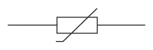
The Thermistor is a temperature sensor that works on the principle of varying resistance with temperature.
They are made of semiconducting materials.
A thermistor is made of oxides of metals such as Nickel, Manganese, Cobalt, Copper, Uranium, etc.
It is available in a variety of shapes and sizes. Commonly used for configurations are Disk type, Beads type, and Rod type.
There are two types of thermistors:
1. Negative Temperature Coefficient (NTC)
when the temperature increases, resistance decreases. Conversely, when temperature decreases, resistance increases. It is a commonly used type.
2. Positive Temperature Coefficient:
When temperature increases, the resistance increases, and when temperature decreases, resistance decreases. This type of thermistor is generally used as a fuse.
Uses:
Thermistors act as a passive components in a circuit.
They are an accurate, cheap, and robust way to measure temperature.
While they do not work well in extremely hot or cold temperatures, they are the sensor of choice for many different applications.
They are ideal when a precise temperature reading is required.
SIMULINK MODEL OF THERMISTOR CONTROLLED FAN:
The working operation comprises various electrical and mechanical blocks as follows:
1. SIGNAL BUILDER:
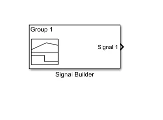
The Signal Builder block allows for the creation of interchangeable groups of piecewise linear signal sources and their use of them in a model.
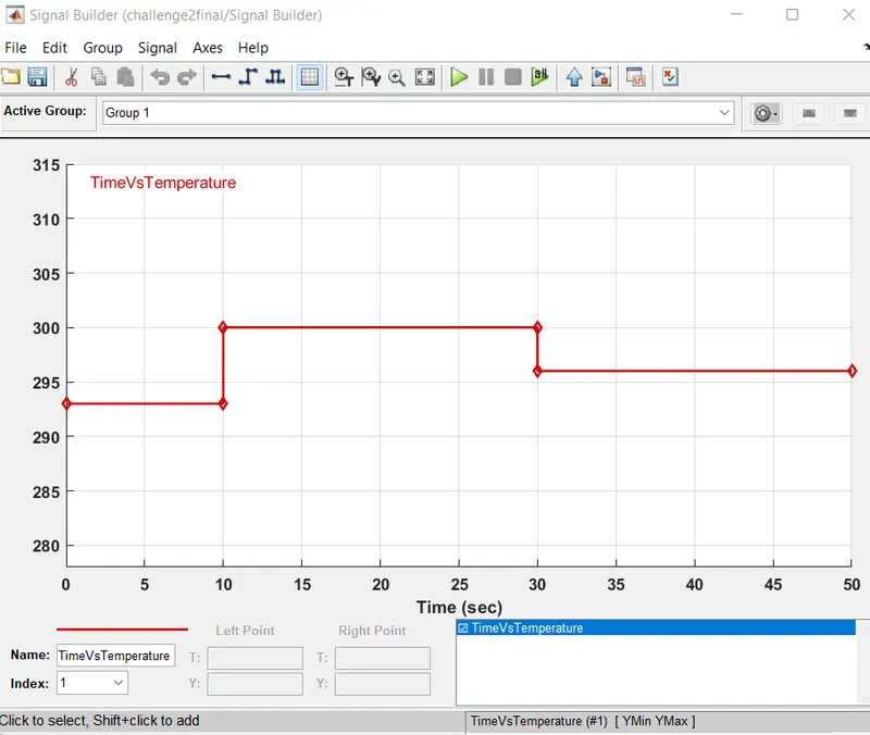
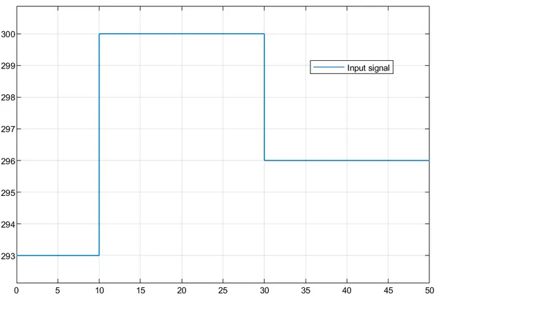
In the Signal Builder window, create signals and define the output waveforms. The signals are created based on the input conditions; 1.0 to 10 sec 20 deg c (293.15K) 2.10 to 30 sec 27 deg C (300.15 k) 3.30 to 50 sec 23 deg C (296.15 k) w The time range of the signals are assigned from 0 to 50 seconds and the signals are built based on the temperature ranges
2. Simulink to PS converter
Using a filter to make the signal smooth and eliminate the output error
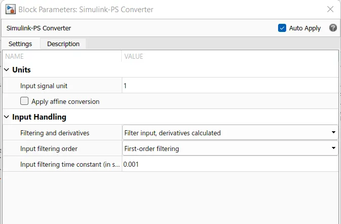
The Simulink signals are converted into physical signals by using Simulink -PS converter. Then the signals are connected to a controlled temperature source.
3. Controlled Temperature Source
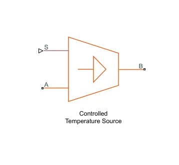
The Controlled Temperature Source block represents an ideal source of thermal energy that is powerful enough to maintain specified temperature differences across the source regardless of the heat flow consumed by the system.
Connections A and B are thermal conserving ports corresponding to the source inlet and outlet, respectively. Port S is a physical signal port, through which the control signal that drives the source is applied. The built signal is converted and connected to a controlled temperature source block.
The temperature differential across the source is directly proportional to the signal at the control port S. THERMISTOR Negative Temperature Coefficient (NTC) thermistor using B-parameter equation are used to pass the generated controlled signals into a thermistor, where the thermistor senses the temperature of the heater and passes the signal based on desired conditions.
4. Solver Configuration
The Solver Configuration block specifies the solver parameters that the model needs before beginning simulation. Each topologically distinct Simscape block diagram requires exactly one Solver Configuration block to be connected to it.
5. Electrical Reference
The Electrical Reference block represents an electrical ground. Electrical conserving ports of all the blocks that are directly connected to the ground must be connected to an Electrical Reference block.
6. Resistor
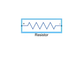
The Linear resistor in electrical systems is connected to the ideal voltage sensor to determine the flow of current through the circuit.
7. Battery
The terminals of the battery are connected to the sensors and thermistor block to flow the current through the circuit and the desired voltage ranges are identified using a voltage sensor.
8. Voltage Sensor
The Voltage Sensor block represents an ideal voltage sensor, that is, a device that converts voltage measured between two points of an electrical circuit into a physical signal proportional to the Connections voltage. + and are electrical conserving ports through which the sensor is connected to the circuit. Connection V is a physical signal port that outputs the measurement result.
9. PS to Simulink Converter
This block Converts physical signal into Simulink output signal, The measured voltage range values are identified for 25 deg C. To turn the fan on, the regulated voltage value are been determined when the voltage is increased as per the input conditions.
10. Display
The converted signals are connected to the display, to identify the threshold value of the temperature of 25 deg c. The threshold value is used as a control parameter in the switch block.
11. Scope
The scope block display time-domain signals, the scope displays simulation results
12. Switch
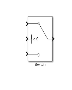
The Switch block passes through the first input or the third input signal based on the value of the second input. The first and third inputs are data inputs. The second input is a control input. Specify the condition under which the block passes the first input by using the Criteria for passing the first input and Threshold parameters.
13. Controlled Voltage Source
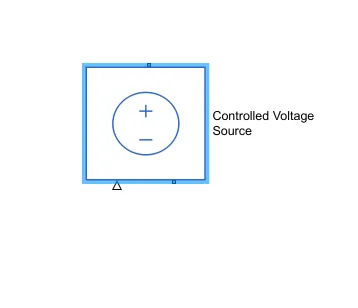
The Controlled Voltage Source block represents an ideal voltage source that is powerful enough to maintain the specified voltage at its output regardless of the current flowing through the source. The threshold is satisfied the signals are converted into Simulink to physical signals and pass through it.
14. DC Motor
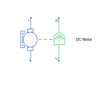
DC motor model with electrical and torque characteristics and fault modeling. In which the electrical signals are transferred into the motor to run and the electrical signals are converted to mechanical signals which are been monitored by an ideal rotational motion sensor.
15. Ideal Rotational Motion Sensor:
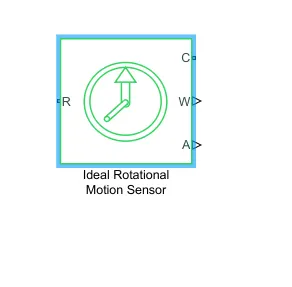
The ideal Rotational Motion Sensor block represents an ideal mechanical rotational motion sensor, that is, a device that converts a variable measured between two mechanical rotational nodes into a control signal proportional to angular velocity or angle. Connections R and C are mechanical rotational conserving ports that connect the block to the nodes whose motion is being monitored. Connections w and A are physical signal output ports for velocity and angular displacement, respectively.
DESIGN AND SIMULATION OF THERMISTOR CONTROLLED FAN USING SIMULINK:
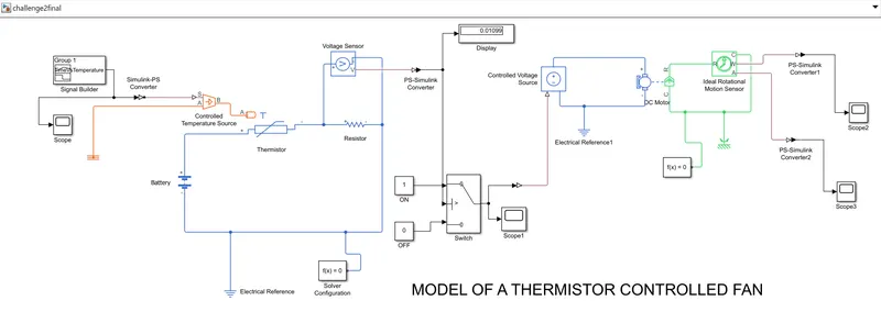
MODEL LINK:
WORKING:
1. INPUT SIGNAL:
The signal builder is used to build the input signal based on the input conditions. Then the signals are converted to physical signals and connected with a controlled temperature source. The output of the signal is visualized using a scope. From the respective FROM block, the signals are retrieved. The controlled temperature signals are passed to the thermistor
2. SWITCH SYSTEM:
The switches conditions are used. The two constant blocks are used to provide the constant values and at port2 the threshold value is assigned at 25 deg o. From the voltage sensor, the threshold value is monitored. From the threshold value if it satisfies the respected time interval(@ 10 - 30 sec) and a 25 deg c the fan is in ON condition otherwise it will be turned OFF.
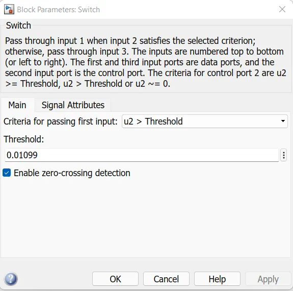
The threshold value is noted from the display of the voltage sensor and the values are assigned as 0.01099. If the threshold value is satisfied the signals then pass through the controlled voltage sources.
3. ELECTRO-MECHANICAL SYSTEM
The conditioned signals are converted and passed through a controlled voltage source.
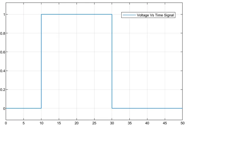
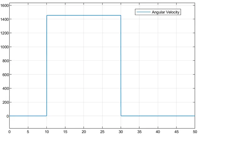
From which the DC motor actuated based on the threshold value (Voltage). Based on the Voltage rise @ 10 sec the fan is in ON condition till 30 sec. Then the fan is in OFF condition. The measured motor speed is noted as 1454rad s.
The result of the input signal, voltage signal, and Angular velocity, angle are portrayed. From it is observed that at 10- 30 seconds the fan is in ON condition in another state that is from 0-10 seconds and 30-50 seconds the fan is in OFF condition.
PLOTS:
1. INPUT SIGNALS BY USING SIGNAL BUILDER:
2. OUTPUT SIGNAL FOR VOLTAGE VS TIME USING SWITCH SYSTEM (FAN ON/OFF):
3. ANGULAR VELOCITY OF FAN
4. ANGULAR DISPLACEMENT OF FAN:
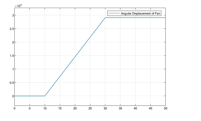
From the above plot it is evident that between the region of 10 - 30 seconds, the plot is linear. Therefore, the fan is ON in these states while from 0 - 10 seconds and 30 -50 seconds the curve is flat which means that the fan is idle and is OFF.
CONCLUSION:
I. We have observed the plunger movement of a doorbell when the switch is closed for 2 seconds and then released.
II. Heater temperature is being sensed by using a thermistor and later we found the threshold value. By using a DC motor configuration we found that the fan is on from 10 to seconds above a temperature range of 25D C.