Week -2
AIM:
To make a Simulink model of doorbell using a solenoid block and observe the physical movement of the plunger.
Given Condition:
Switch is closed for 2 seconds and then released.
Blocks used:
- Pulse Generator
- Switch
- Solenoid
- Ideal translational motion sensor
- Mechanical translational Reference
- Electrical Reference
- Scope
Connection Logic:
- Create a Simulink file and Save it as Doorbell.
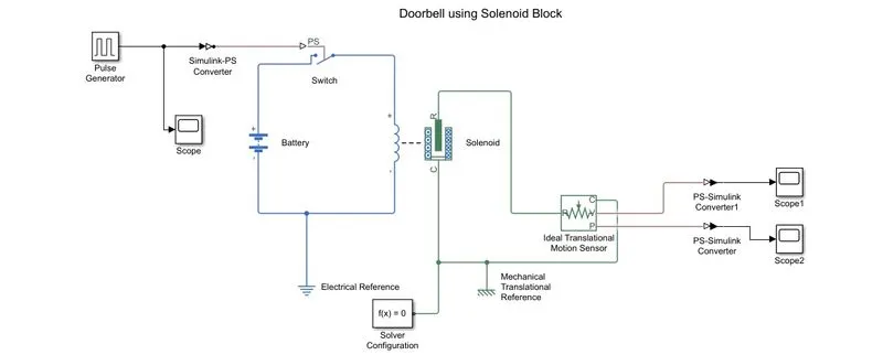
- Insert a Solenoid block and connect it a battery and also add a switch.
- Pulse generator block inserted to achieve the desired condition.
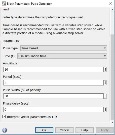
- Condition implemented by giving period as 4 seconds and pulse width as 50% of 4 seconds, i.e, 2 seconds.
- The signal from the pulse generator was converted using a Simulink-PS convertor and is given as the input to the switch.
- First order filtering is done on Simulink-PS converter.
- The voltage of battery connected was made as the same as that of rated voltage of solenoid.
- The position of solenoid plunger is measured using an ideal translational motion sensor connected to circuit.
- Both mechanical and electrical references were connected to respective
- The output from the ideal translational motion sensor is converted using a PS-Simulink convertor and is given to the scope to display the results.
- A scope was also connected to input to visualize its behaviour.
Inputs:
Pulse generator block parameters:
Simulink Block Diagram:
Simulink Model Link:
https://drive.google.com/file/d/1Ui3HkdrrmMTHH0owkr1Tc6P3k5fZ_6nk/view?usp=sharing
Input Scope Plot:
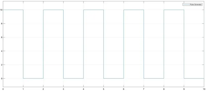
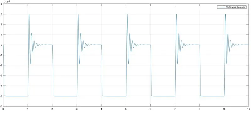
for the simulation time of 10 seconds here we can see that pulse generator is making 5 cycles of 2 seconds.
Output:
Plunger Velocity plot:
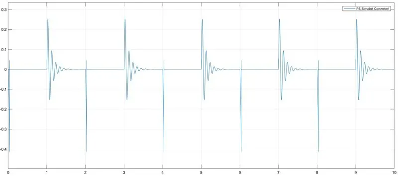
Plunger Position plot:
Observation:
As we can see from the above plot, motion is getting generated for 2 seconds and set idle for 2 seconds, this loop is repeated throughout the simulation time.
AIM 2:
To use Thermistor to sense temperature of a heater and turn on/off the fan in Simulink
Given Condition:
Temperature source - 20°C from 0 to 10 seconds, 27° C from 10 to 30 seconds, 23°C from 30 to 50 seconds.
Fan Conditions – ON if temperature above 25°C , OFF otherwise.
Blocks Used:
- Signal Builder
- Controlled temperature Source
- Thermistor
- Voltage sensor
- Current sensor
- DC voltage source
- Solver Configuration
- Thermal reference
- Electrical reference
- Switch
- Scope
- Display
- Simulink-PS convertor
- PS- Simulink convertor
Theory:
Thermistor is a semiconductor that has a resistance capacity than a inducting material and less than insulating material. Its electrical resistance varies with the change in the temperature or thermally sensitive resistor.
Thermistors have high sensitivity which can be up to 10 percent change per degree Celsius and their typical response time is 0.5 to 5 seconds with an operating range from -50 to 300°C and there are devices with more capacity.
Connection Logic:
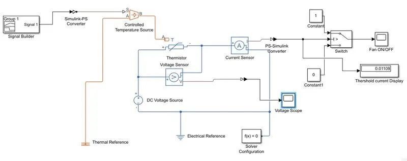
- A thermistor block is represented and connected to DC voltage source respective to there terminals( 12 V to block parameter of DC voltage source).
- A voltage sensor block sensor block connected parallel to thermistor to sense voltage drop and current sensor block in series to sense current drop.
- Thus, we have completed our simple circuit model, but we need some physical quantities to as signal for thermistor to work.
- In this case we need fan to get ON and OFF at different temperatures so to provide temperature we used Controlled Temperature Source Block to send temperature signal.
- To give different temperature to CTS block we need to send temperature signals.
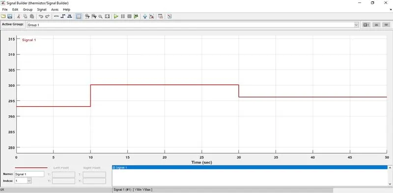
- To send the required type of signal we have to use signal builder block and customise signal accordingly. i.e,
- 293.15K for 0 to 10 seconds
- 300.5 K for 10 to 30 seconds
- 296.15 K for 30 to 50 seconds
( Simulink-PS convertor is added in between CTS and signal builder block with first order filtered input derivatives).
- Now port ‘B’ of CTS block is connected to port ‘A’ of the thermistor block and port ‘A’ of CTS block is connected to thermal reference block
- Also Electrical reference and solver configuration is added to the electrical circuit.
- Now, the output of voltage sensor and current sensor block is connected to scope and run the simulation to see voltage and current drop. (PS-Simulink converter in between them)
- We found that there was no voltage drop and but current drop is there.
- We added the switch to the output of current sensor by giving the threshold we achieved i.e, 0.01109 and connect to scope.
Inputs:
Signal Builder Block:
Simulink Block Model:
Link to the Simulink Model:
https://drive.google.com/file/d/16yxglXyhLC2pgYFwMue-HFZ8gD9SI2x7/view?usp=sharing
Output:
Output plot of switch:
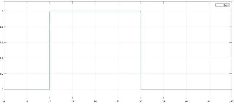
here, we can observe that switch is ON in between 10 to 30 seconds only when the temperature is 300.15 K.
Voltage sensor plot:
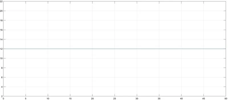
Here, we can see there is no voltage drop through out the simulation.
Conclusion:
We made the simulink model of thermistor controlled fan switch which turns on when the temperature is above 25 deg celcius.