Week -2
Aim
1. Make a Simulink model of Doorbell using solenoid block with the following details:
- Create a situation where the switch is closed for 2 seconds and then released. Observe the physical movement of the plunger.
2. Use a thermistor to sense the temperature of a heater & turn on or turn off the fan as per the below conditions:
-
Temperature source: 20 °C from 0 to 10 seconds, 27 °C from 10 to 30 seconds, 23 °C from 30 to 50 seconds
-
Fan conditions: ON if the temperature above 25 °C, OFF otherwise
Objective - 1
- Make a Simulink model of Doorbell using solenoid block with the following details:
- Create a situation where the switch is closed for 2 seconds and then released. Observe the physical movement of the plunger.
Methodology
Theory
Solenoid
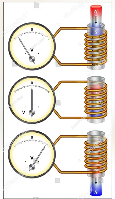
A solenoid is a type of electromagnet that consist of a helical coil of wire of suitable length which is substantially greater than its diameter, and a movable plunger that placed inside the coil. The current passing through the coil generates a controlled magnetic field around the coil. The coil can produce a uniform magnetic field in a volume of space when an electric current is passed through it. This magnetic field make the plunger move in and out of the coil which utilized in doorbell mechanism.
Doorbell Mechanism
The doorbell uses the principle of electromagnetism where the current passing through the coil make the plunger inside coil to act as magnet that attract the iron strip which strike on the bell to produce sound. The arrangements are shown below.
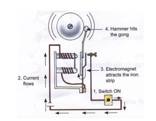
When the switch is on the current flows through the coil and make the plunger to act as magnet and attract the iron strip whose one end is connected to the spring and the other end touches the contact breaker point to complete circuit as shown in the figure. The hammer that hits the bell to produce sound also attached to the iron strip. The electromagnet attract the iron strip and the iron strip moves left and the hammer attached hits the bell and produce sound. During this the movement of strip cut the connection to the contact breaker point and the circuit breaks and the plunger demagnatized and the iron strip back to original position, touch the contact breaker which make the circuit on and above process repeat. This is how it works.
Simulink Blocks Used
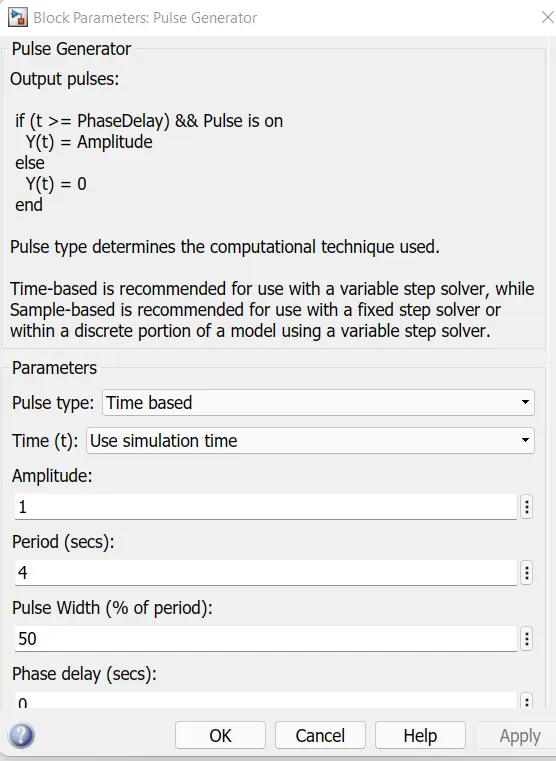
Pulse Generator : It is used to generate square wave pulses to control the switch of the circuit. The switch should be closed for 2 sec and then released so the pulse generator helps to do it. The parameters are provided properly to produce signals.
Goto block : It is like a tag. It sends signals to From block that have the specified tag. We can access the signals using From block.
Simulink-PS Convertor Block : It used to Converts the Simulink input signal to a Physical Signal.
Switch Block : This block is electrical switch that controlled by an external physical input signal. There is threshold value above which the switch gets activated. If the external input signal is greater than threshold value then the switch is closed.
Battery Block : This block represent a battery that provide a constant supply to the solenoid and produce a electromagnet.
Solenoid Block : This block represent a sloenoid which combines the electro-mechanical characteristics of a solenoid. It convert the electrical signals to equivalent mechanical signals.
Mechanical Translational Reference Block : This is the block that represent a mechanical translational reference point, simply saying it acts as a frame or a ground. We can use it to connect mechanical translational ports that are rigidly affixed to the frame (ground).
Electrical reference Block : Block that represent electrical reference point, that is an electrical ground. Electrical conserving ports of all the blocks that are directly connected to ground must be connected to an Electrical Reference block. A model with electrical elements must contain at least one Electrical Reference block.
Solver Configuration Block : It represent a solver configuration that specifies the solver parameters that the model needs before the begining of simulation.
Ideal Translational Motion Sensor block :It represent a motion sensor. This block measures velocity or displacement in a mechanical translational network. The V and P ports represent the physical signal ports which report the velocity and position, respectively, of port R relative to port C. The measured velocity is positive when the velocity at port R is greater than the velocity at port C.
PS-Simulink Converter Block : It Convert the physical signal from motion sensor to simulink output signal.
From Block : It is the block that receive signals from the Goto block with the specified tag.
Scope : This the block used to display signals generated during simulation.
Explanation
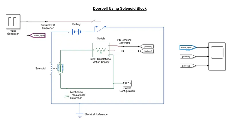
The pulses generated using pulse generator which control the switch given to the switch after converting the simulink input signals to physical signals using Simulink-PS converter. Switch is closed for 2 sec during which the current passes through solenoid and get magnetised. The electromagnet moves the plunger which finaly leads to the striking of bell and production of sound. The motion of plunger is recorded by ideal translational motion sensor. The physical signal output from the sensor converted to similunk signals using PS-Simulink converter. Using scope block the signals generated are displayed.
Simulink Block Diagram
Output
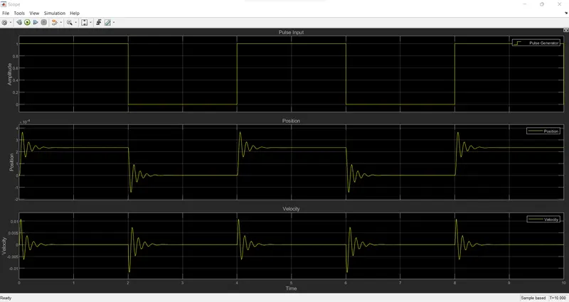
Here the simulation time is 10 seconds and the input pulse signal is provided during each 2 seconds, that is for making the switch remain close for 2 seconds. The display shows the position of the plunger during each magnetization of solenoid, that is passing the electric signals to coil which creat magnetic fields which finaly leads to plunger movement and there by ringing the bell. From the display the motion of plunger is damped one.
Conclusion
- The Simulink model of Doorbell using solenoid block is created and exicuted successfully.
- The motion of plunger is displaied correctly ucing scope.
- Helps to identify the motion of plunger and its characteristics.
Google Drive Link : https://drive.google.com/file/d/1vT5wwP64W_f20drsnljjI4fI1tr77pWH/view?usp=sharing
References
- https://www.mathworks.com/help/releases/R2021b/physmod/sps/ref/solenoid.html
- https://skill-lync.com/knowledgebase/how-to-use-lookup-table-in-simulink
Objective - 2
2. Use a thermistor to sense the temperature of a heater & turn on or turn off the fan as per the below conditions:
-
Temperature source: 20 °C from 0 to 10 seconds, 27 °C from 10 to 30 seconds, 23 °C from 30 to 50 seconds
-
Fan conditions: ON if the temperature above 25 °C, OFF otherwise
Theory
Thermistor
A thermistor is a type of thermal resistor which works on the principle of varying resistance with respect to the temperature. It can be defined as a temperature sensor whose resistance is varies with the temperature. It is a semiconductor made up of oxides of metals such as Nickal, Cobalt, copper etc., that has electrical conductivity in between conductors and insulators. There are 2 types of thermistors, Negative temperature coefficient thermistors (NTC)- Whose resistance value decreases with increase of temperature and Positive temperature coefficient thermistors (PTC)- Whose resistance value increases with increase of temperature. NTC thermistor used in different applications like temparature measurement, temperature control etc. PTC thermistors circuit protection, current limiting resistors etc.
Here we use the thermistor to sense the temperature of the heater and turn on or off the fan. If temperature is above 25 °C fan is on, and OFF otherwise.
Simulink Blocks Used
Signal Builder Block : Used to generate the input signals according to the input signal requirments given. Here the conditions given are :
For INPUT
- 0 to 10 sec : 20 °C (293.15 K)
- 10 to 30 sec : 27 °C (300.15 K)
- 30 to 50 sec : 23 °C (296.15 K)
For OUTPUT
- Fan should be ON if temparature is greater than 25 °C (298.15 K) otherwise OFF
Simulink-PS Convertor Block : It used to Converts the Simulink input signal to a Physical Signal.
Goto block : It is like a tag. It sends signals to From block that have the specified tag. We can access the signals using From block.
Controlled Temperature Source Block : It represent an Ideal energy source that controlled by the physical temeperature signals from Simulink-PS convertor at the S port of the block. It can maintain a controlled temperature difference regardless of the heat flow rate. Input physical signals are given through the S port of the block. output is taken from B port.
Thermistor Block : It represent a NTC thermistor whose resistance value decreases with increase of temperature. 'A' is the thermal port on which the out put from the B port of temperature source is given. The +ve and -ve ports are the electrical conserving ports.
Thermal Reference : Reference point in a thermal network where the temperature is equal to absolute zero.
Battery : It represent a battery that provide a constant supply to the thermistor and act as a part of an electrical circuit which helps in identifying the variations in the electrical resistance of the circuit.
Resistor : It is the block that represent the simple resistor that obey Ohm's law. It provide the resistance to the flow of current which hleps in identifing the variations in the resistance of circuit.
Voltage Sensor Block : It represent a voltage sensor that identify the variations in voltages across the resistor due to the temperature changes and output the equivalent physical signals. It should connected in parallel.
Electrical reference Block : Block that represent electrical reference point, that is an electrical ground. Electrical conserving ports of all the blocks that are directly connected to ground must be connected to an Electrical Reference block. A model with electrical elements must contain at least one Electrical Reference block.
PS-Simulink Converter Block : It Convert the physical signal from voltage sensor to respective simulink output signal.
Switch : It represent a block that passes a certain signals based on satisfying certain preassigned criterions. It has 3 ports, Port-1 is first data input port, Port-2 is Control input port, Port-3 is second data input port. Based on the control input signals in the 2nd port the block determines whether to pass the first input signal or second input signal to the output. If the criteria for passing the first signal which has set in the criteria for passing first input parameter, the block passes the 1st input otherwise passes 2nd input.
Controlled Voltage Source Block : It represent an ideal voltage source that maintain a specified voltage signals at output based on the input signals provided.
DC Motor : This block represents a DC motor model and characterised by the electrical and torque characteristics of a DC motor. It is an electromechanical block that takes an electrical input signal and gives mechanical rotational output.
Ideal Rotational Motion Sensor Block : This act as a motion sensor which senses the output rotational motions of mechanical blocks. It measures the angular velocity and angular displacement. The W-port provide the angular velocity as output signal and A-port provide the angular displacement as output signal.
Solver Configuration Block : It represent a solver configuration that specifies the solver parameters that the model needs before the begining of simulation.
Constant : Provide constant value signals.
From Block : It is the block that receive signals from the Goto block with the specified tag.
Scope : This the block used to display signals generated during simulation.
Explanation
- The input signal is generated using a signal builder by providing the given input conditions. A Goto block provided to display the output signal using scope block.
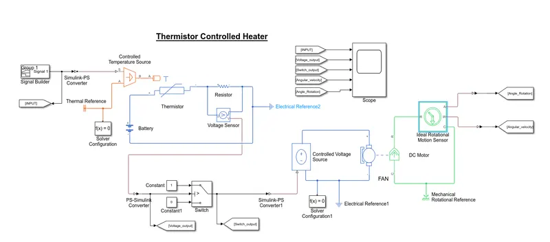
- Converted the signals using simulink-PS convertor and given the physical signal to the S-port of controlled temperature source block which provide temparature signals corresponding to the input physical signals to the A-port of the thermistor block.
- The thermistor +ve port is connected to +ve terminal of battery and -ve terminal of thermistor is connected to the +ve terminal of resistor and the -ve terminal of resistor is connected to the -ve terminal of battery.
- A voltage sensor connected in parallel to the resistor block to detect any changes in the voltages signals in the circuit depending on the temperature changes in the thermistor.
- The signals out from the voltage sensor is a physical signals. It converted to simulink signals using PS-simulink convertor blocks and gives the simulink signals to the Switch block.
- The switch block represent a block that passes a certain signals based on satisfying certain preassigned criterions. It has 3 ports, Port-1 is first data input port, Port-2 is Control input port, Port-3 is second data input port. Based on the control input signals in the 2nd port the block determines whether to pass the first input signal or second input signal to the output. If the criteria for passing the first signal which has set in the criteria for passing first input parameter, the block passes the 1st input otherwise passes 2nd input.
- Here we set in the criteria for passing first input parameter as, if the temperature is greater than 25 °C (298.15 K) it passes the 1st data input signal ( ON signal for switch on the fan) otherwise passes 2nd data sinput signal. For this we have to set a threshold value which is the value of voltage sensor output corresponding to the 25 °C (298.15 K) temperature signal. The voltage sensor output value is 0.011964 V.
- The output from the switch is converted to physical signals using Simulink-PS convertor and the physical signal is given to the controlled voltage source where it produces voltage signals corresponding to the input signals inorder to activate the rotating part (fan).
- Here the DC motor represent the fan which is rotated by the signals from the voltage source according to the given input conditions.
- The motion of the fan is recorded by the ideal roational motion sensor. The W port of sensor give the angular velocity signals of the fan and the A port provides the Angular displacement of the fan which are displayed by using the scope as shown below.
Simulink Block Diagram
Output
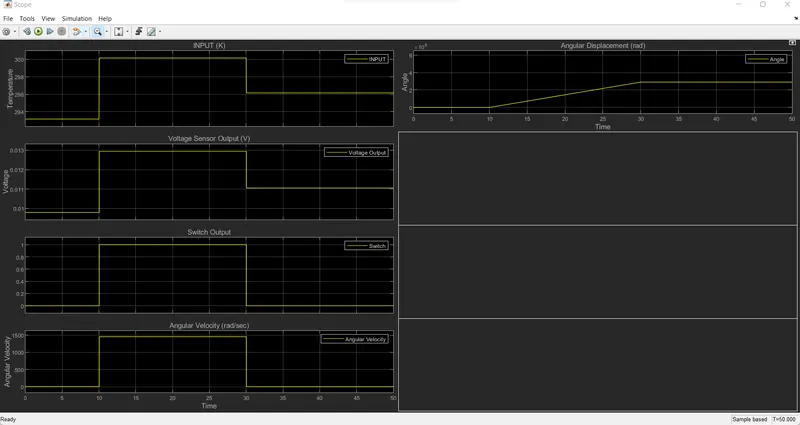
- From analysing the plot we can find that the switch output is zero during the time 0 to 10 sec and 30 to 50 sec. This is because of the input condition provided to the switch. Here we set the threshold value of switch as 0.011964 V ( Voltage sensor output corresponding to the 25 °C (298.15 K)) above which the 1st data input signal (Constat value of amplitude 1 unit) is passed which represent the ON position of FAN. Otherwise it pass 0 as output which indicate OFF position of FAN.
- During 0 to 10 sec the temperature is 20 °C (293.15 K) and 30 to 50 sec temperature value is 23 °C (296.15 K) which are below the threshold limits 25 °C (298.15 K) which results in OFF position of FAN. It is clear from the plot also the angular velocity is zero during these period.
- And from the angular displacement graph there is no increse in angular displacement during these periods.
Conclusion
- The objective to form a simulink model of thermistor controlled heater that sense the temperature of the heater & turn on or turn off the fan as per the given input conditions exicuted successfully.
- Working and behaviour of various simulink block understand verywell.
- Finout the threshold value of switch block and using this able to ON and OFF the Fan.
Reference
- https://skill-lync.com/knowledgebase/thermistor-challenge
- https://skill-lync.com/knowledgebase/why-is-filtering-required-and-how-to-solve-the-error-related-to-that
- https://www.electrical4u.com/thermistor/
Google drive link