Week -2
AIM: To create a simulation for a door bell and thermistor cotrolled fan.
OBJECTIVES:
- Make a simulation model of a doorbell using a solenoid and observe the movement of the plunger when the switched is closed for 2 secs and then realesed.
- Use thermister to sense the tempreture of a heater and turn off fan as per below conditions.
- Tempreture source: 20'C from 0 to 10 seconds, 27'C from 10 to 30 seconds,23'C from 30 to 50 seconds.
- Fan conditions:ON if the tempreture above 25'C,OFF otherwise.
TASK 1:
Model diagram:
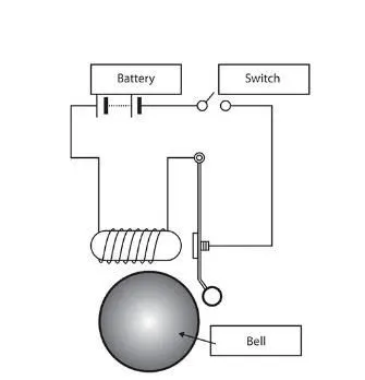
- The following is the siplified diagram of door-bell.
Simulink Block Diagram :
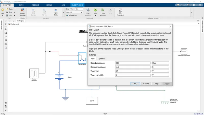
- The following is required simulink block diagram of the door bell.Each element is explained in detail in the following steps.
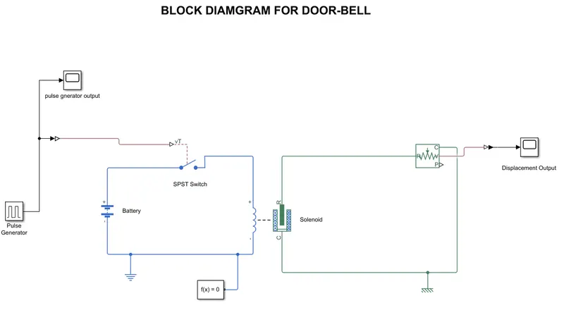
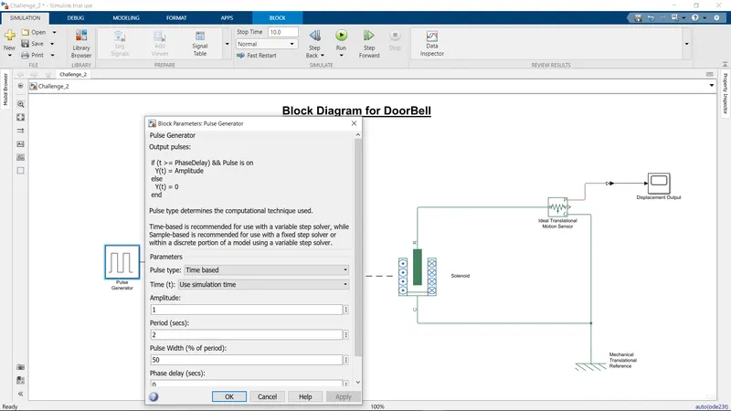
- A pulse generator is used to achieve the automatic switching machanism for the SPST switch ,where its closing ON for 2 seconds and released.We can see the graph from the scope linked to pulse generator.
- The SPST switch has threshold of 0.5 and it is linked to the battery and the electic part of the solenoid. In order to make the switch close,the external control signal (vT) generated by the pulse generator should be greater than the threshold of the switch.
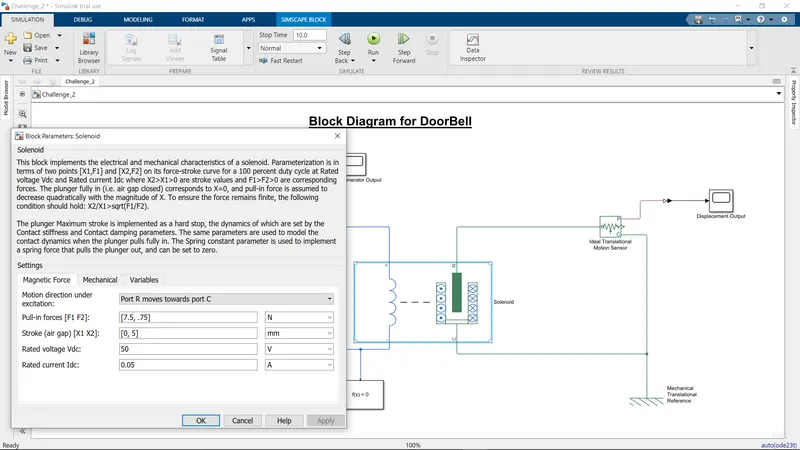
- A Solenoid is device comprised of coil of wire, the housing and a moveable plunger(armature).When aan eletric current is introduced, a magnetic field forms around the coil which draws the plunger in.THe moments of the plunger can be seen graphically from a scope linked to an IDEAL TRANSLATIONAL MOTION SENSOR.
OUTPUT:
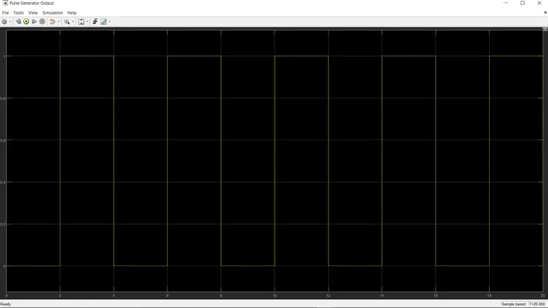
- The following is the output plot of the pulse generator. We can observer that ,the signal is turned on orr every 2 sec.Alternatively ,it's in OFF mode for 2 sec .Thus,we achieved the required input.
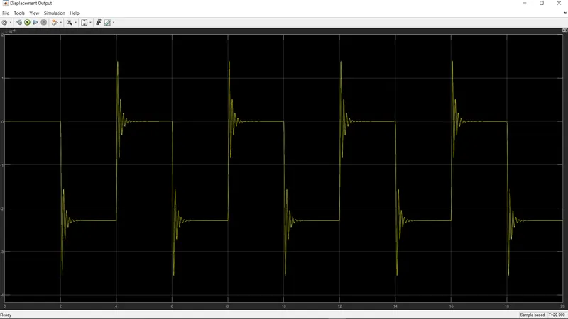
- The following is the output plot for the displacement of the plunger of the solenoid. The ripples at beginning and ending of pulse signals are due to the eletical interface.Thus,movements of plunger are been observed.
TASK 2 :
Simlimulink block diagram:
The followingis the required simuulink block diagram fir turnung ON or OFF the fan,where a thermister is used to sense the tempreture of heat source inturn triggering to trun ON or OFF the fan.The details of elements in the simulink model are explained in the further steps.
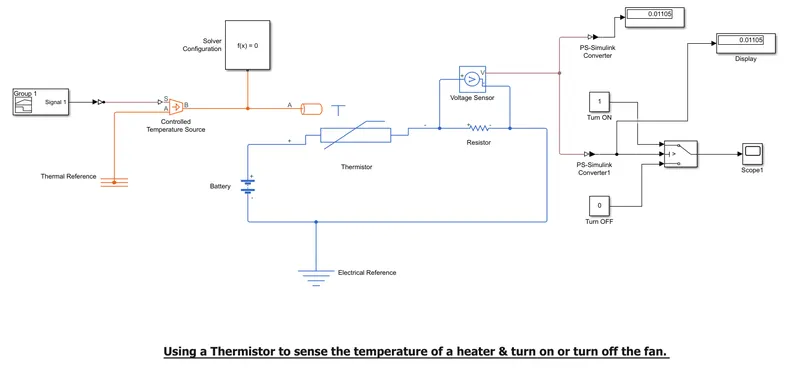
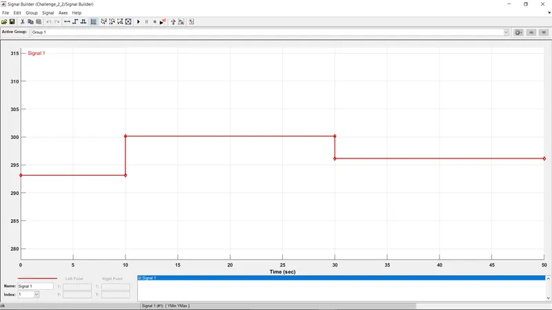
- THE SIGNAL BUILDER PLOT where our required tempreture points are achieved.The tempreture source are set to the followingconidtions:
- For time set ' 0 to 10 ' seconds:the tempreture range is '293.15k'
- For time set '10 to 30' seconds: the tempreture range is '300.15k'
- For time set '30 to 50' seconds:the tempreture range is '296.15k'
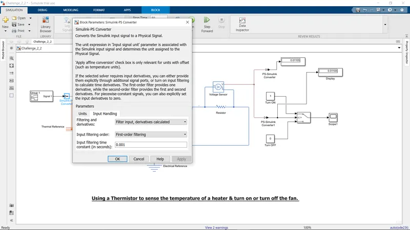
- The SIMULINK-PS converter converts the simulink signals to a physical signal.As signal builder is a complete block unlike a constant block,we're required to let more derivatives to be activated.For this, the filtering and derivativeties parameters of SImulink-ps block is set to 'Filter input,derivatives caculated'option.Otherwise,there will be an error in the output.
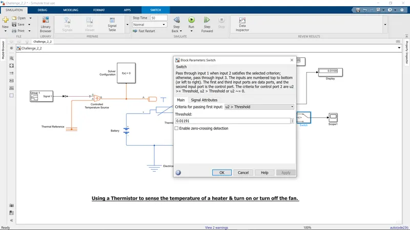
- After trials and errors the trashhold switch required to achieve the expexted output is been noted as '0.01191'.'1'represents ON and '0' represents OFF.
OUTPUT:
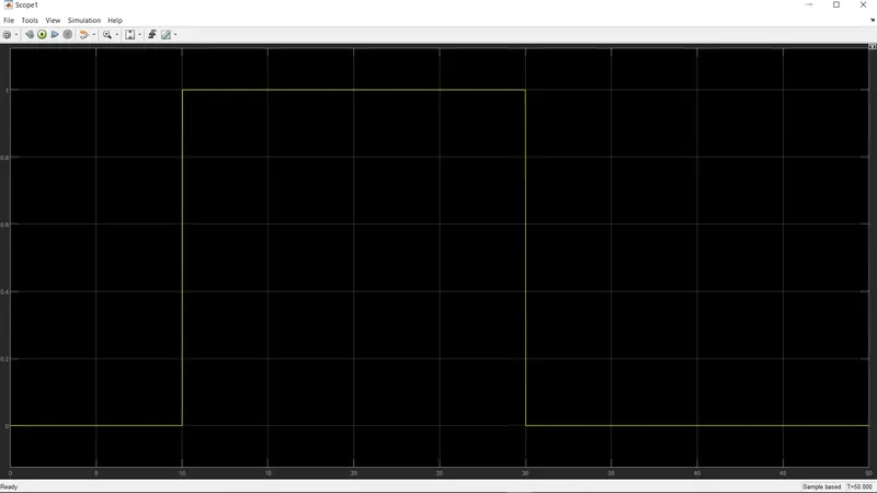
- The following output is the simulink model.We can observe that,the signal rreaches the TRUN ON mode from the time range 10 to 30. This output is similer to the input given in the Signal builder.Thus,our simulation is correct and required output is achieved.