Week -2
a) Door bell Simulink model:
Objectives:
- To create the simulink model to simulate the working of a doorbell.
- To observe the physical movement of plunger based on the input provided.
Condition:
Switch is closed for two seconds.
Model:
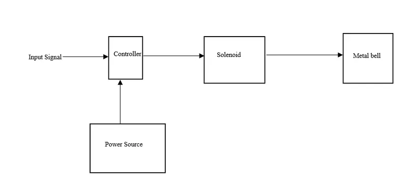
Above figure shows the model based description of door bell which contains four major parts which are power source , controller , solenoid and metal bell. Power source can be taken as a simple dc source battery, which provides the power to energized the solenoid. When solenoid is energized, it pushes the plunger towards the metal bell, due to the strike of plunger on metal bell, a sound is produce. A controller is used to control the process of energizing for solenoid. In above door bell problem, a switch is used as a controller. Based on the input signal provided by the user , Switch closes or open the circuit. When Circuit is open, sound is not produce while in close condition sound is produced. For above mentioned problem , switch is close for 2 seconds.
Simulink Model:
Block Used:
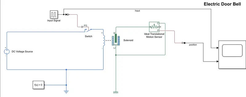
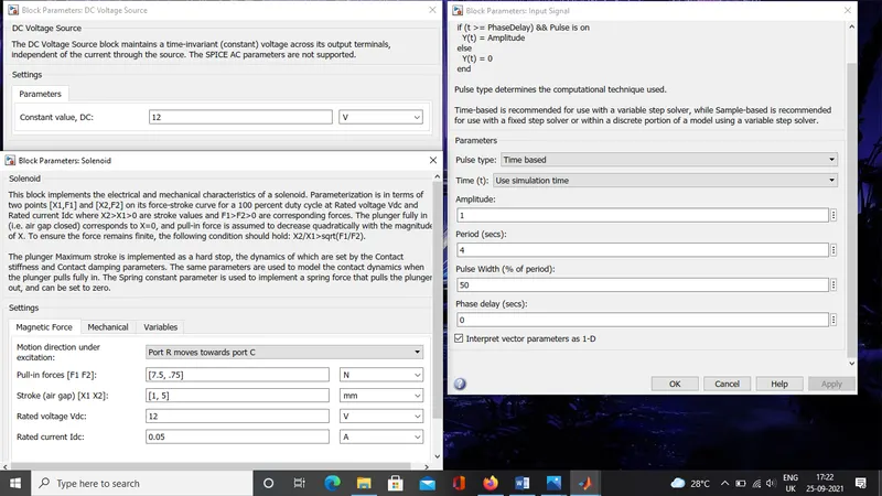
Pulse Generator: This block is used to create the signal as per condition. In this case, a signal for time period of 4 seconds is generated, for 2 second the signal have the amplitude of 1 while for next 2 second signal will have amplitude of 0. Amplitude of 1 represents as on position while 0 represents off position.
Switch: A switch is used as a controller. When signal amplitude is 1 it closes the circuit and for 0 it opens the circuit.
DC Voltage Source: 12 V constant dc voltage source is used in order to energize the solenoid.
Solenoid: As per the mechanism of solenoid, when it is energized it pushes the plunger inside of it the metal bell and sound is produce. Solenoid rates voltage is taken as 12V and air gap of 5 mm is considered.
Ideal translational motion sensor: It is used to observe the position of the plunger.
Reference: Electrical reference and mechanical translational motion referenece is used.
Converter: Two converter are used for above simulink model. one is physical signal to simulink (to converts the signal from simscape model to simulink signal) and next is simulink to ps (To convert signal from simulink to simscape signal).
Scope: To visualize the output of simulation.
Input:
Output:
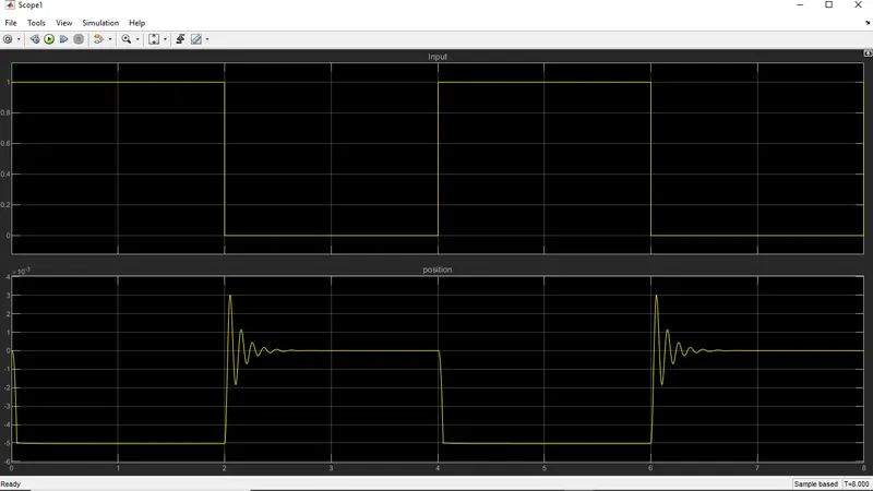
At input plot we can observe that , for first two second input signal has the amplitude of 1 which corresponds the on signal and next 2 seconds the amplitude value is 0 which corresponds the off signal. When on signal is provides we can observe that the plunger position is around 5mm and after this off signal is provided. When time is around 2-3 second, we can observe the position of plunger is flucatating, this is due to the lower damping coefficient. After some flucatation plunger comes to rest. Similar observation is seen for rest of the time period.
b) Automatic Fan:
Objective:
To create a simulink model for automatic fan which works as per the below mentioned conditions.
Conditions:
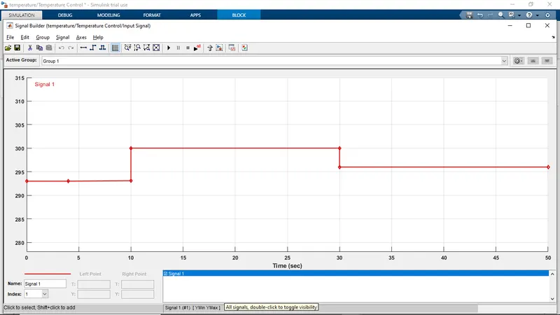
- Input signal should be provided in a such a way that for first 10 seconds , temperature should be 20 degree celcius, for next 20 seconds it should be 27 degree celcius and for last 20 second the temperature should be 23 degree celcius.
- Fan should only be operate when temperature is above 25 degree celcius.
Model:
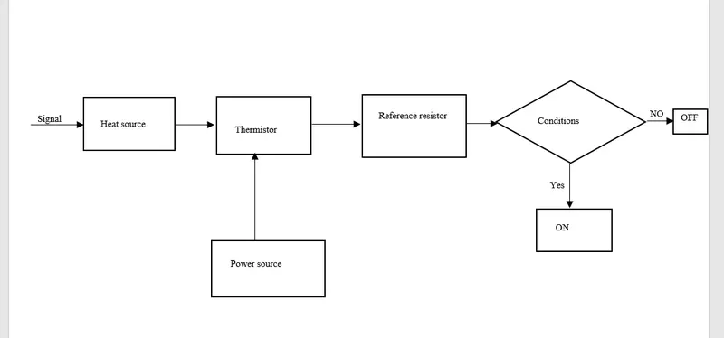
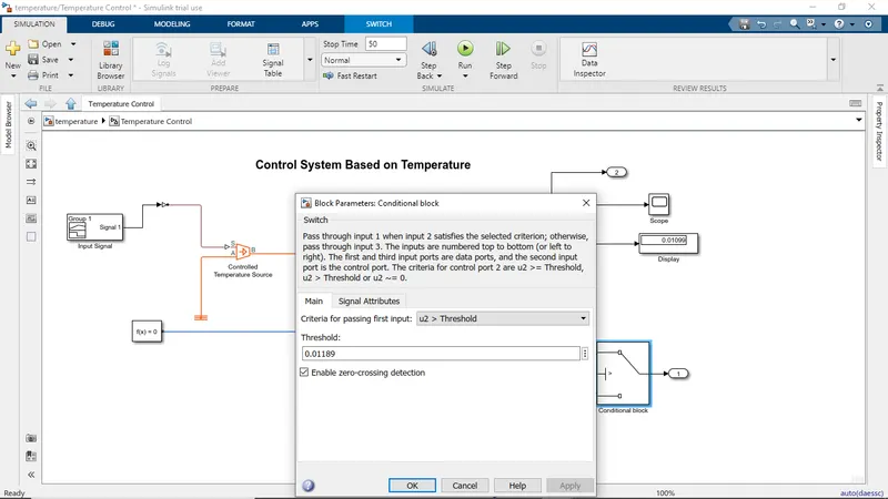
Based on the input signal the temperature from the heat source changes. Thermistor is a device whose resistance changes with change in the temperature. In our case we are using PTC i.e. it resistance increase with increase in temperature. A refereenc resistor is used where we are measuring the voltage across the it. For differenet temperature the voltage across the reference resistor is different. A power source i.e a battery is connected to thermosister. Based on the voltage measure across the reference resistor, an simple dc motor is driven which is connected to the fan. So, when the temperature is more than 25 degree celcius , than the motor is turned on.
Simulink Model:
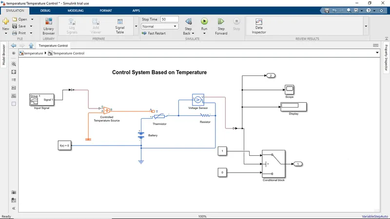
Simulink model for control system based on temperature.
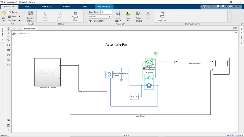
simulink model which is control by the above control system.
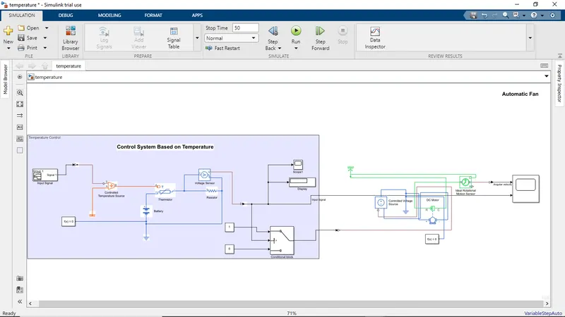
Whole simulink model.
Block used:
Signal builder: This block is used to provide the signal as per the above mentioned conditions.
Controlled Temperature Source: This block acts as a source and provides the temperature output as per the input signal given to it.
Thermistor: With the change in the temperature output signal, resistance of the thermistor is changed.
Resistor: A reference resistor is used in order to measure the voltage across the circuit, when the temperature is changed.
Voltage Sensor: Voltage sensor is used to measure the voltage.
Battery: It provide power to the thermistor.
Switch: It acts as a conditional/ control system for the fan/motor. If the measure voltage is more than the thresold value than only it will provide signal for motor/fan to rotate else it wonot rotate.
DC Motor: It acts like a motor connected to the fan and when motor rotate fan also rotate as fan propeller is connected to the shaft of the motor.
Constant DC Source: To provide power to the motor.
Ideal rotational motion sensor: It is used to know, whether the motor is running or not by measuring its angular velocity.
References: Thermal ,electrical, and mechanical rotational reference are used.
Scope: Used to visulize the output.
Constant block
PS to simulink converter
Simulink to PS converter
Solver configuration
Input:
Signal from signal buider:
Output:
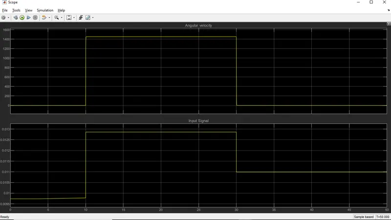
It is observed that , with change in the temperature , voltage across the reference resistor is changing. The maximum voltage was seen was seen for the temperature of 27 degree celcius. From the angular velocity plot it was clear that the motor/fan was rotate for 10-30seconds as we can observe the angular velocity for this time period. In this time period the temperature of the system was more than 25 degree celcius.
Conclusion:
Simulink model for door bell and automatic fan was made as per the conditions and simulated.