Simulation of Otto Cycle
Project: Codes to solve otto cycle
Objectives:
- To obtain pressure and volume for different process and plotting them to obtain PV diagram for cycle.
- To determine thermal efficiency by considering the compression ratio for modern petrol engine vehicle
Theory:
Otto cycle which is also called as constant volume cycle, is the fundamental for working of petrol engine. Working of petrol engine completes in 4 stroke , first intake, followed by compression stroke, than power stroke and at last exhaust stroke. This four stroke of engine is completed by two thermodynamic process i.e. constant volume process and adiabatic process.
In Intake stroke, charge is sucked inside the combustion chamber as piston moves from TDC to BDC.
In compression stroke, Piston starts to moves form BDC to TDC position as a result , pressure and temperature of charge inside the combustion chamber increases.
In power stroke: Charge is ignited, as pressure and temperature inside the chamber increases which pushes the piston from TDC to BDC.
In exhaust stroke , by product of combustion process is pushed out from the combustion chamber to begins the next stroke.
In terms of thermodynamic process
When the charge is sucked inside the combustion chamber, charge is compressed adiabatically. Then heat is added in constant volume , which increases the pressure and temperature inside the combustion chamber.This process is followed by adiabatic expansion process , where pressure and temperature inside the chamber decreases.At last constant volume heat rejection process takes place.Figure shows the PV diagram for otto cycle.
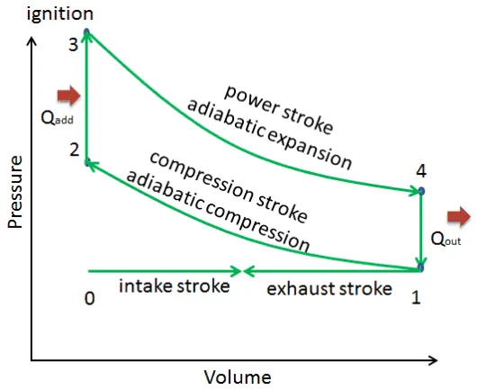
Figure 1: PV diagram for otto cycle by showimg all the processes[1]
Code Logic:
First , calculate pressure and volume at the end of every stage by using the governing equation. When all the point are determine, study how the volume and pressure changes with respect to crank angle. On basis of obtain pressure and volume plot the PV diagram. In order to determine the thermal efficiency, governing equation has to be solved.
Governing equation;
For Adiabatic Process:
`PV^gamma=Constant`
For Constant Volume process
`P prop constant * T`
To find swept volume and clearance volume
vs=(pi/4)*bore^2*stroke;
where vs = swept volume
vc=vs/(rc-1)
where, vc = clearance volume , rc= compression ratio
To find the engine kinematic/study volume and pressure change with respect to crank angle
`v=(1+1/2(rc-1)[R+1-costheta-sqrt(R^2-sin^2theta)])*vc`
where, `theta`=crank angle , R=connecting rod length/a, a=stroke/2
To find thermal efficiency of cycle
`eta=1-1/r_c^(gamma-1)`
Steps:
1: Input all the require parameters like bore, stroke, compression ratio , connecting rod length etc.
2: Find the value for pressure and volume at every stage like v1, p1, p2 , p3 etc
3: In order to find volume change with respect to crank angle,create a different function for example engine. And from the function take an output of volume change.
4: Based on the pressure and volume at different state, plot the PV diagram with respect to volume change for different crank angle.
5: Create an array to store the value for different compression ratio from 1 to 15.
6: Use the formula and calculate thermal efficiency for different compression ratio.
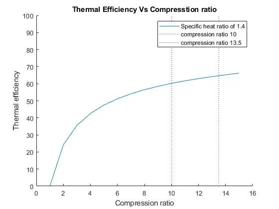
7: As for modern petrol engine, compression ratio lies from 10 to 13.5 , plot a line to distinguish the theortical thermal efficiency of modern petrol engine.
Codes:
%otto cycle PV diagram
close all
clear all
clc

%Parameters Input

p1=10^5;
t1=533;       % Temperature at the end of suction stroke
gamma=1.4;    % as medium is air
t3=2500;

%Engine parameters
bore=0.2;
stroke=0.15;
con_rod= 0.25;
rc=10;

%Volume calculation
vs=(pi/4)*bore^2*stroke;
vc=vs/(rc-1); %clearance vol. can be taken starting of suction stroke


%Different value of pressure and volume at different stage

% At end of suction stroke

v1=vc+vs; %Total volume

%At the end of adiabatic compression
v2=vc;  %volume at the end of compression stroke

p2=p1*rc^gamma; % Pressure at the end of compression stroke

t2=p2*v2*t1/(p1*v1); % Temperature at the end of compression stroke
constant=p1*v1^gamma;
vcom=engine(bore,stroke,con_rod,180,360); %calling the fucntion (angle is 180 -360 degree)
p_com=constant./vcom.^gamma;

%Constant volume heat addition process

v3=v2;

p3=p2*t3/t2;

%At the end of adiabatic expansion
v4=v1;
p4=p3*(v3/v4)^gamma;
constant=p3*v3^gamma;
v_exp=engine(bore,stroke,con_rod,0,180); %calling a function
p_exp=constant./v_exp.^gamma;


%Plotting Different pressure and volume points for different stage
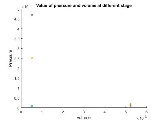
figure(1)
hold on
title('Value of pressure and volume at different stage')
plot(vc,p1,'*') %starting of intake stroke
plot(v1,p1,'*') %At the end of intake stroke
plot(v2,p2,'*') %At the end of adiabatic compression
plot(v3,p3,'*') %At the end of constant volume heat addition
plot(v4,p4,'*') % At the end of adiabatic expansion
axis([0 6*10^-3 0 5*10^6])
xlabel('volume')
ylabel('Pressure')
hold off


%connection of those point by considering volume and pressure change with
%respect to crank angle

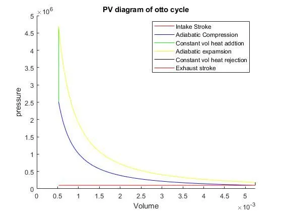
figure(2)
hold on
axis([0 v1 0 5*10^6])
xlabel('Volume')
ylabel('pressure')
plot([vc,v1],[p1,p1],'Displayname','Intake Stroke','color','r')  %For Intake stroke
plot(vcom,p_com,'Displayname','Adiabatic Compression','color','b') % For adiabatic Compression
plot([v2,v3],[p2,p3],'Displayname','Constant vol heat addtion','color','g') %For Constant Volume heat addition
plot(v_exp,p_exp,'Displayname','Adiabatic expamsion','color','y') %For adiabatic expansion
plot([v4,v1],[p4,p1],'Displayname','Constant vol heat rejection','color','k') % For Constant volume heat rejection
plot([v1,vc],[p1,p1],'Displayname','Exhaust stroke','color','r')
title('PV diagram of otto cycle')
legend
hold off


%To calculate thermal efficiency for variable compression rate


cr=[1:15];
k1=(cr.^0.4);
eff1=(1-k1.^-1)*100;


figure(3)
hold on
title('Thermal Efficiency Vs Compresstion ratio')
plot(cr,eff1,'displayname','Specific heat ratio of 1.4')
plot([10,10],[0,100],':','color','k','displayname','compression ratio 10')
plot([13.5,13.5],[0,100],':','color','k','displayname','compression ratio 13.5')
axis([0 16 0 100]);
xlabel('Compression ratio')
ylabel('Thermal efficiency')
legend
Function Codes
%Defining a function to compute volume change with respect to crank angle

function [v]=engine(bore,stroke,con_rod,start_crank,end_crank)


rc=10;
a=stroke/2;
R=con_rod/a;
theta=[start_crank:end_crank]; %value for crank angle
vs=(pi/4)*bore^2*stroke;
vc=vs/(rc-1);


trm1=0.5*(rc-1);
trm2=R+1-cosd(theta);
trm3=(R^2-sind(theta).^2).^0.5;

v=(1+trm1*(trm2-trm3)).*vc; %formula to find volume for different crank angle
end
Result:
Different point for otto cycle
PV diagram of otto cycle
Thermal efficiency vs compression ratio
Conclusion
- Value for different points has been determined and plotted in a PV diagram.
- Thermal efficiency vs compression ratio has been plotted and theoritical thermal efficiency for modern automobile petrol engine was in range og 60-65%.
References:
1.https://www.nuclear-power.com/nuclear-engineering/thermodynamics/thermodynamic-cycles/otto-cycle-otto-engine/?pdf=17545