Week -2
OBJECTIVE
- To Make a Simulink model of Doorbell using solenoid block where the switch is closed for 2 seconds and then released.
- To Use a thermistor to sense the temperature of a heater & turn on or turn off the fan .
1.DOORBELL
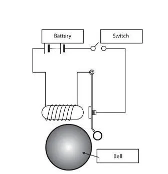
In the above arrangement, when the switch is closed the electromagnet receives electrical power from the battery and pulls
the metal arm to hit the bell producing sound.
A solenoid is a device comprised of a coil of wire, the housing and a moveable plunger (armature). When an electrical current
is introduced, a magnetic field forms around the coil which draws the plunger in. More simply, a solenoid converts electrical
energy into mechanical work.
MODEL:
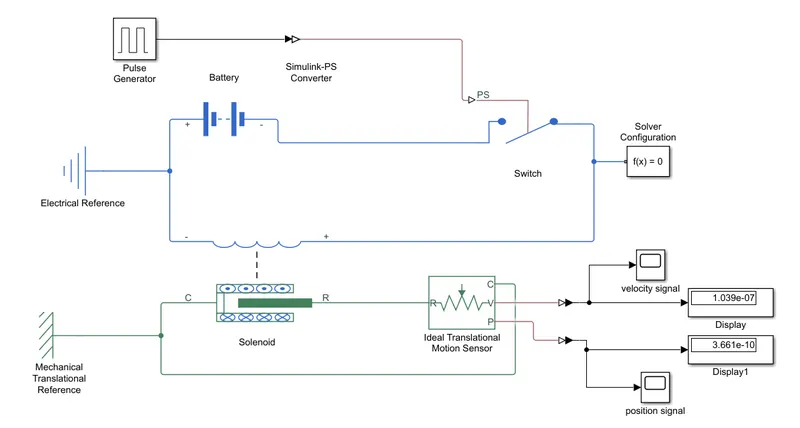
First of all a pulse generation is created and input has been given.
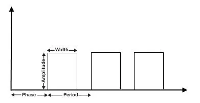
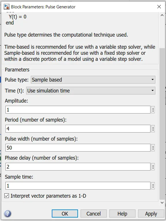
Amplitude is set as 4. Pluse width is given as 50%. Phase delay is given as 2 seconds.
The pulse generated is converted into physical signal using simulink-PS converter.
It is further connected to the switch.a battery is connected to the switch and both of them are connected to the solinoid.
The r port of the solinoid is further connected to the r port of the ideal translational motion sensor, which sences the signal coming from solinoid.
The ideal translational motion sensor is having 3 output port ,c port is connected to the c port of the solinoid.the other two ports ie, velocity and position ports are connected to two displays and are scoped respectively.
Electrical reference is given to the electrical circuit and mechanical translational reference is given to the mechanical part.
Solver configuration is connected.
RESULT
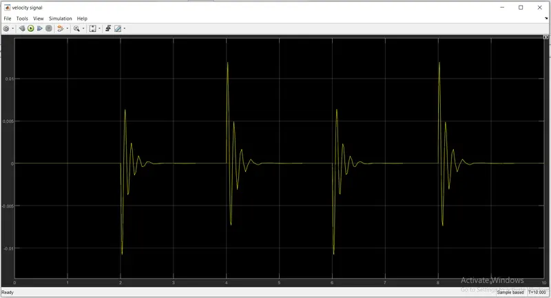
OUTPUT OF VELOCITY:
OUTPUT OF POSITION:
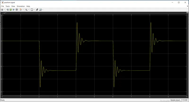
The amplitude showsn at the bottom shows the bell is ringing at an interval of 2 seconds with the phase delay of 2 seconds.
2.Use a thermistor to sense the temperature of a heater & turn on or turn off the fan as per below conditions:
Temperature source: 20 °C from 0 to 10 seconds, 27 °C from 10 to 30 seconds, 23 °C from 30 to 50 seconds
Fan conditions: ON if the temperature above 25 °C, OFF otherwise
A thermistor is a resistance thermometer, or a resistor whose resistance is dependent on temperature. The term is a
combination of “thermal” and “resistor”. ... When temperature increases, the resistance increases, and when temperature
decreases, resistance decreases.
MODEL:
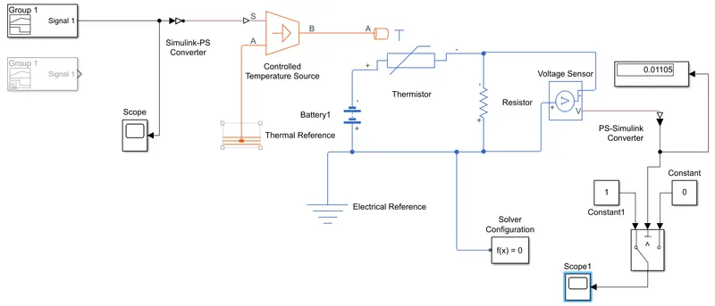
The pulse generator is created in such a way that its 20 degrees from 0 to 10 sec , 27 degrees from 10 to 30 sec , 23 degrees from 30 to 50 sec.
The fan is functioned in such a way that it the temperature comes aboove 25 degree , the fan is onn otherwise it is off.
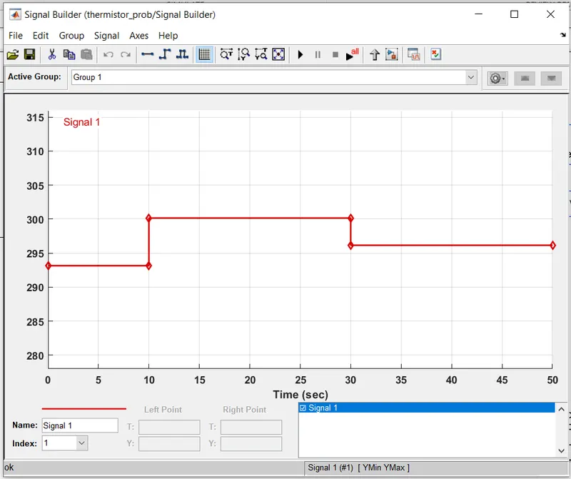
A signal builder is created in such a way that ,20 degrees from 0 to 10 sec , 27 degrees from 10 to 30 sec , 23 degrees from 30 to 50 sec.
The display limits of t is set as 50 sec and and y is set as 300.
The degree values are converted into kelvin unit.
Another signal builder is created with 298.15k(25 degree celsius) and simulation is run.the thershold at 15 degree celsius is found and is displayed .
The second signal buider is disconnected and commented out. The first signal builder is connected to the simulink ps signal converter.
The signal from the builder is the converted into physical signal using simulink ps converter.
Further connected to the controlled temperature source.it maintain a controlled temperature difference regardless of the heat flow rate.
It is futher connected to thermistor using portb to a of the thermistor.
The thermistor is connected to battery from the +ve side . The negative end is connected parallely to resisitor and voltage sensor.
A thermal reference is connected to the a port of temperature controlled source.
A electric reference is connected to the electric circuit.
The physical signal from the voltage sensor is coverted into simulink signal using PS- simulink converter.
It is further connected to a three way switch.The threshold is set as 0.01196 (found using 2nd signal builder).
One portof the switch is connected to constand 0 and the other is connected to constand 1.
If the coming signal satisfy the condition ,the signal is passed throught the output of the switch and it is scoped.
solver configuration is connected.
SIGNAL BUILDER 1:
SIGNAL BUILDER 2:
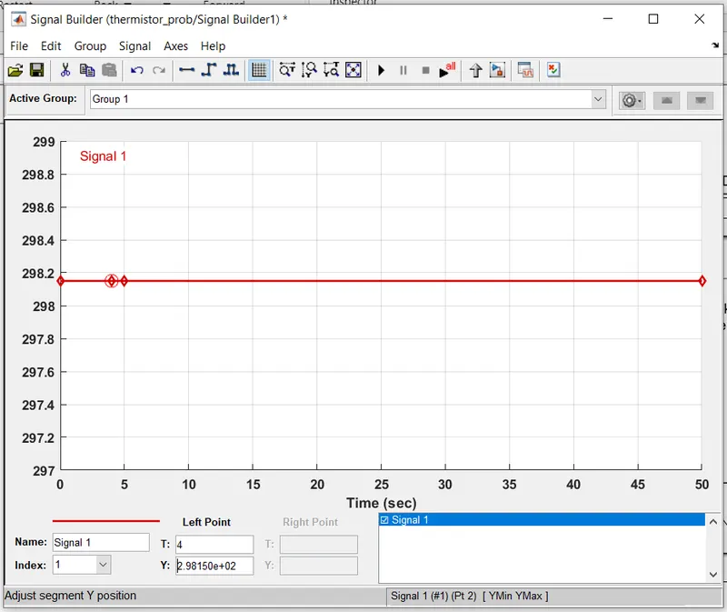
This is found out to find the threshold at 25 degree celsius.
RESULT:
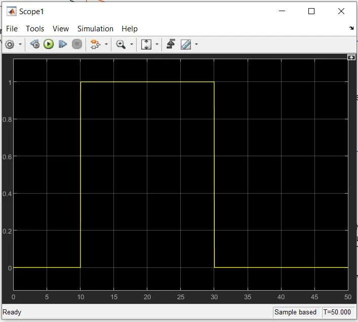
So based on the given contion the fan should only work in the timeperiod of 10 to 30 seconds which is exactly shown in the graph.