Project
AIM:
To carry out a system-level simulation of an all-terrain vehicle using simulink.
ALL TERRAIN VEHICLE:
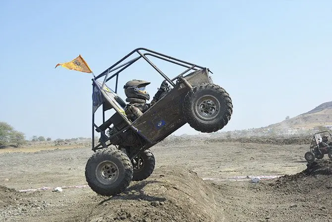
An all-terrain vehicle (ATV), also known as a light utility vehicle (LUV), a quad bike, or simply a quad, is a vehicle that travels on low-pressure tires, with a seat that is straddled by the operator, along with handlebars for steering control. As the name implies, it is designed to handle a wider variety of terrain than most other vehicles.
CONTINOUSLY VARIABLE TRANSMISSION (CVT)
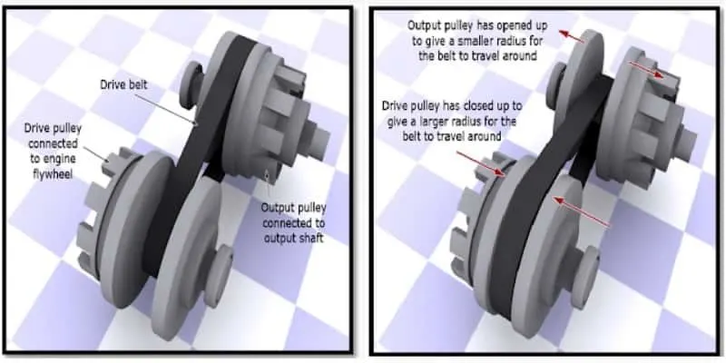
A continuously variable transmission (CVT) is an automatic transmission that can change seamlessly through a continuous range of gear ratios. This contrasts with other transmissions that provide a limited number of gear ratios in fixed steps. The flexibility of a CVT with suitable control may allow the engine to operate at a constant RPM while the vehicle moves at varying speeds.
COMPONENTS USED:
GENERIC ENGINE BLOCK:
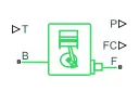
The Generic Engine block represents a general internal combustion engine. This block is a suitable generic engine for spark-ignition and diesel. Speed-power and speed-torque parameterizations are provided. A throttle physical signal input specifies the normalized engine torque. Optional dynamic parameters include crankshaft inertia and response time lag. A physical signal port outputs the engine fuel consumption rate based on the fuel consumption model that you choose. Optional speed and redline controllers prevent engine stall and enable cruise control.
The T is the throttle input signal.
F is the mechanical rotational conservation port associated to the engine crankshaft.
B is the mechanical rotational conservation port associated to the engine block.
P is the physical signal output port which engine power is reported.
FC is the physical signal output port which fuel consumption rate is reported.
VARIABLE RATIO TRANSMISSION BLOCK:

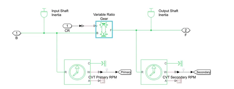
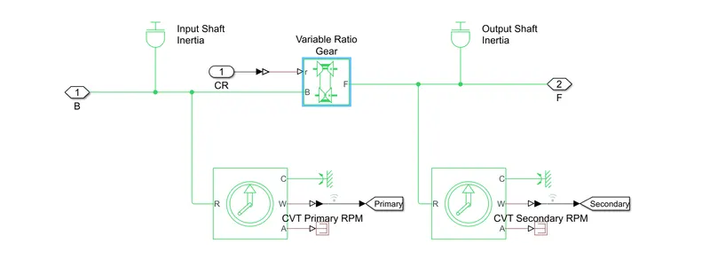
Represents a variable ratio gearbox such as implemented by mechanical belt CVT, electric, or hydraulic transmissions. The physical signal input r defines the ratio of input to output angular shaft velocities.
Connections B (base) and F (follower) are mechanical rotational conserving ports. Specify the relation between base and follower rotation directions with the Output shaft rotates parameter.
SIMPLE GEAR:

The Simple Gear block represents a gearbox that constrains the connected driveline axes of the base gear, B, and the follower gear, F, to corotate with a fixed ratio that you specify. You choose whether the follower axis rotates in the same or opposite direction as the base axis. If they rotate in the same direction, the angular velocity of the follower, ωF, and the angular velocity of the base, ωB, have the same sign. If they rotate in opposite directions, ωF and ωB have opposite signs. You can easily add and remove backlash, faults, and thermal effects.
VEHICLE BODY:
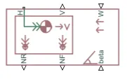
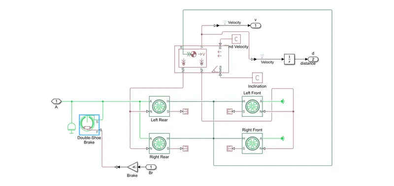
The Vehicle Body block represents a two-axle vehicle body in longitudinal motion. The vehicle can have the same or a different number of wheels on each axle. For example, two wheels on the front axle and one wheel on the rear axle. The vehicle wheels are assumed identical in size. The vehicle can also have a center of gravity (CG) that is at or below the plane of travel.
H is the mechanical translational conserving port associated with the horizontal motion of the vehicle body.
V, NF, and NR are physical signal output ports for vehicle velocity and front and rear normal wheel forces, respectively
W and beta are physical signal input ports corresponding to headwind speed and road inclination angle, respectively.
TIRE(MAGIC FORMULA:

The Tire (Magic Formula) block models a tire with longitudinal behavior given by the Magic Formula [1], an empirical equation based on four fitting coefficients. The block can model tire dynamics under constant or variable pavement conditions.
N is the normal force.
M is the magic formula coefficient.
S, output port is the tire slip.
A is the axle.
H is the hub.
DOUBLE BRAKE SHOE:

Represents a brake arranged as two pivoted rigid shoes symmetrically installed inside or outside a drum and operated by one actuator. The actuator force causes the shoes to exert a friction torque on a shaft connected to the drum.
S is a conserving rotational terminal associated with the drum shaft.
F is a physical signal port representing the force input to the actuator.
Optionally includes thermal effects and expose thermal conserving port H by setting Thermal port to Model.
STUDY 1) CTV MODEL
MODEL:
SUB SYSTEMS:
ENGINE SENSOR:
CONTINOUSLY VARIABLE TRANSMISSION (CVT)
VEHICLE BODY:
BRAKE AND THROTTLE INPUT:
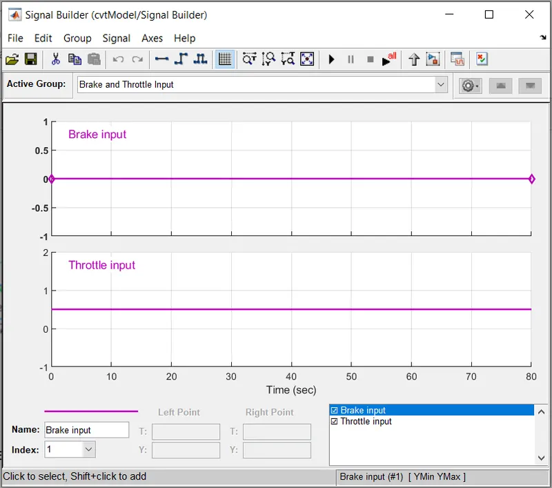
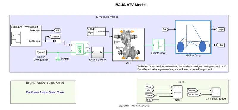
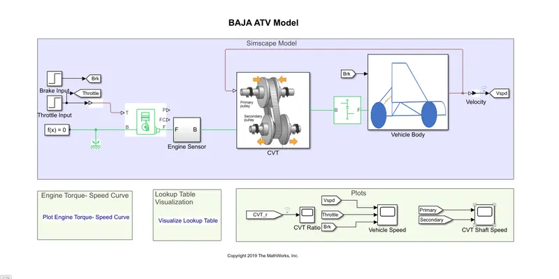
Throttle is given to the generic engine block.
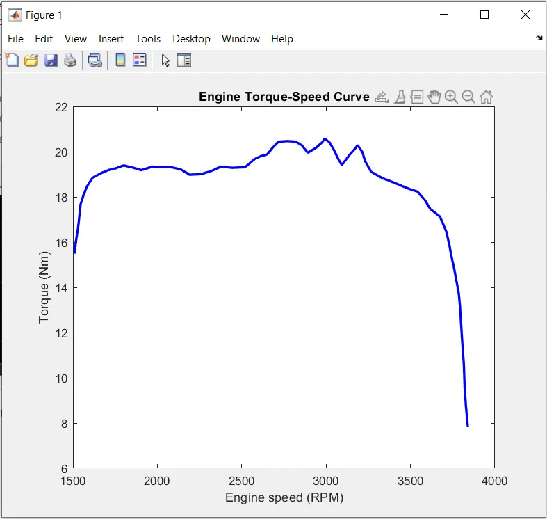
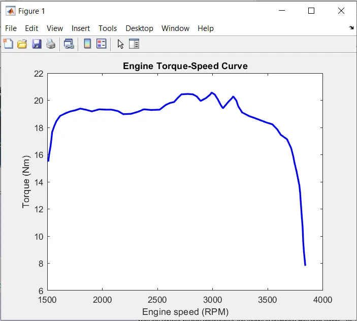
For the generic engine block ,speed vector and torque vector are given as the inputs in matlab workspace.\
The output from the engine block is connected to engine sensor.
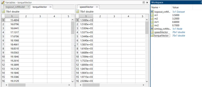
CVT RATIO:
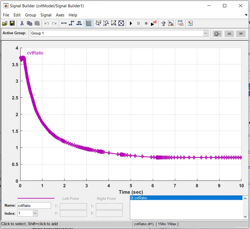
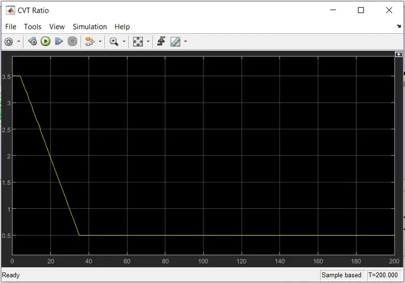
The cvt ratio varies according to time.
The output from the ctv ratio block is connected to the CVT block.
From the Cvt bock it is further connected to simple gear and from there to the vehicle body.
OUPUTS:
ENGINE RPM:
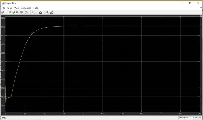
ENGINE RPM VS SPEED CURVE:
VELOCITY,DISTANCE,THROTTLE,BREAK GRAPH:
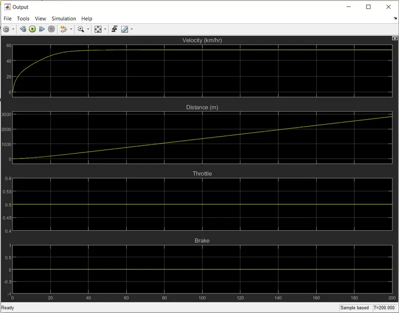
Straight line indicates gear ratio is constant.
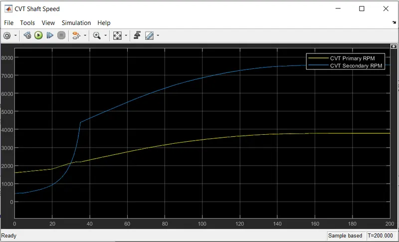
CTV SHAFT SPEED:
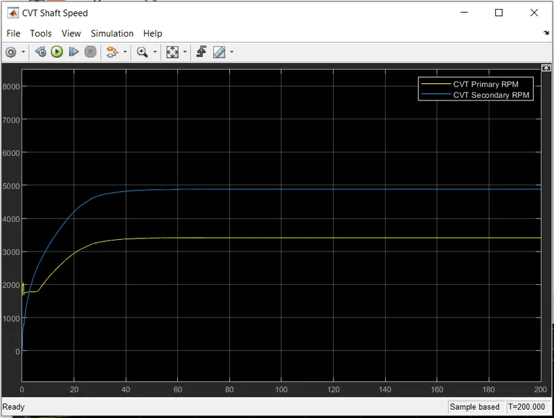
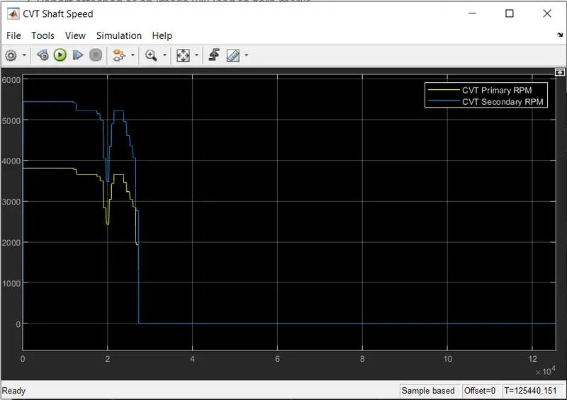
From the intial point RPM of secondary is less than primary,while the simulation continues RPM of secondary becomes more than the primary.
STUDY 2) CTV MODEL DASHBOARD:
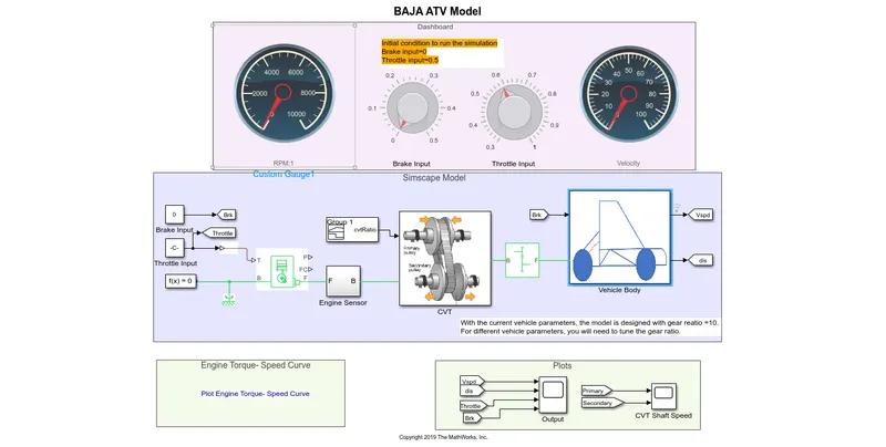
Throttle input and brake input are controlled by knobs.
OUTPUT:
ENGINE TORQUE VS SPEEDCURVE:
VELOCITY,DISTANCE,THROTTLE,BRAKE:
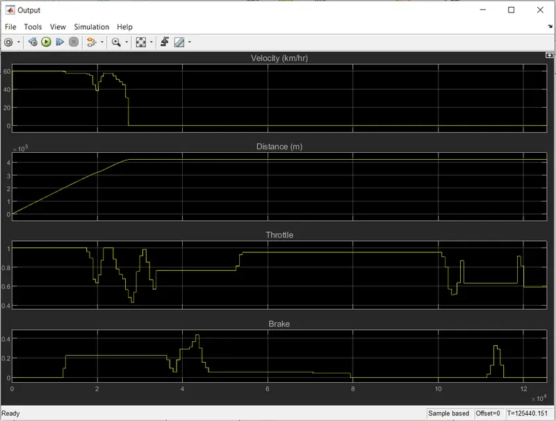
steps are formed as throttle and brake is knob assigned by user.
CVT SHAFT SPEED GRAPH:
STUDY 3) CVT MODEL MAPPED:
MODEL:
FLOW PROCESS:
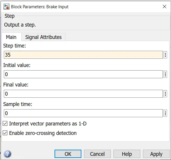
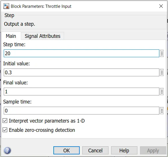
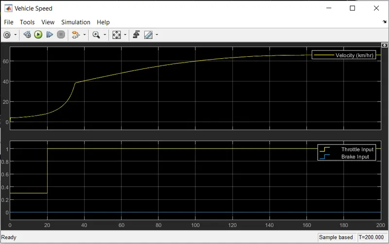
Instead of signal builder , here we are using step block.
The throttle initial is kept as 0.3 and final as 1.
time is set as 20 sec.
BRAKE INPUT:
THROTTLE INPUT:
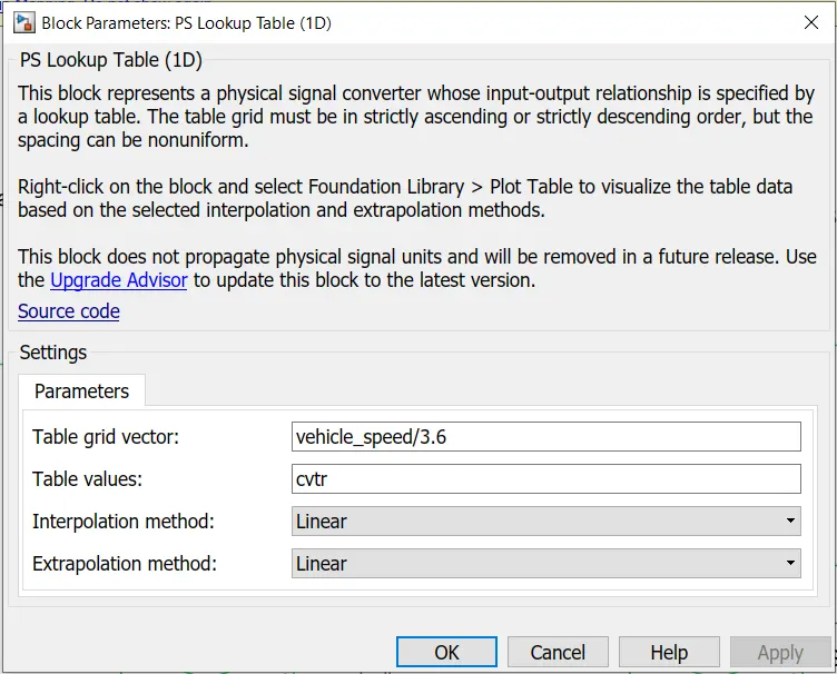
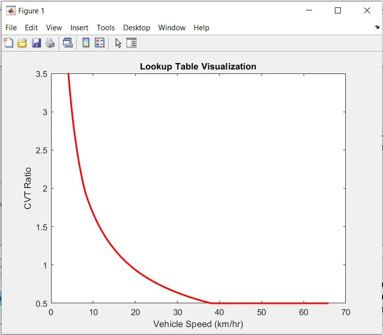
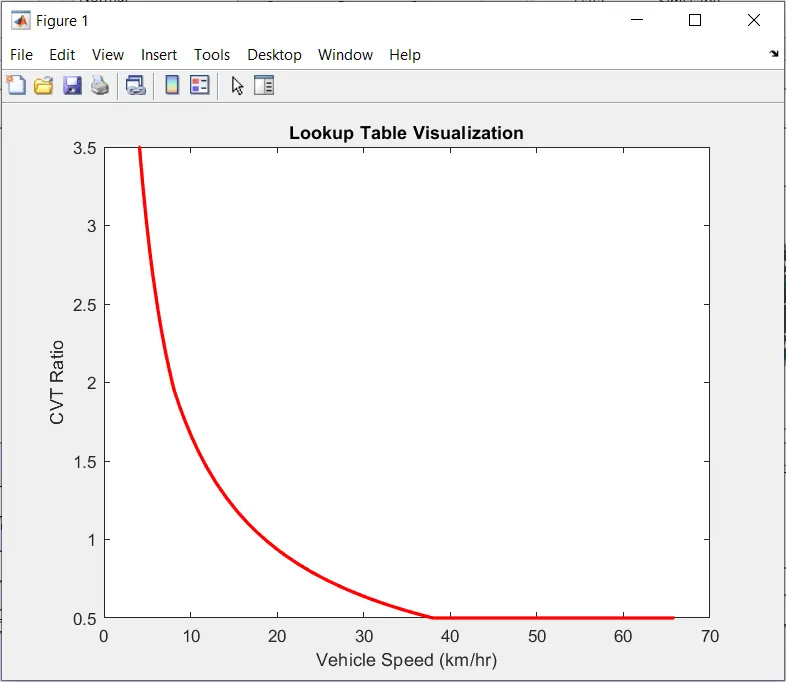
A lookup table is used instead of signal builder,which uses the vehicle speed ,which is used as feedback signal for lookup table.
LOOKUP TABLE:
OUTPUT:
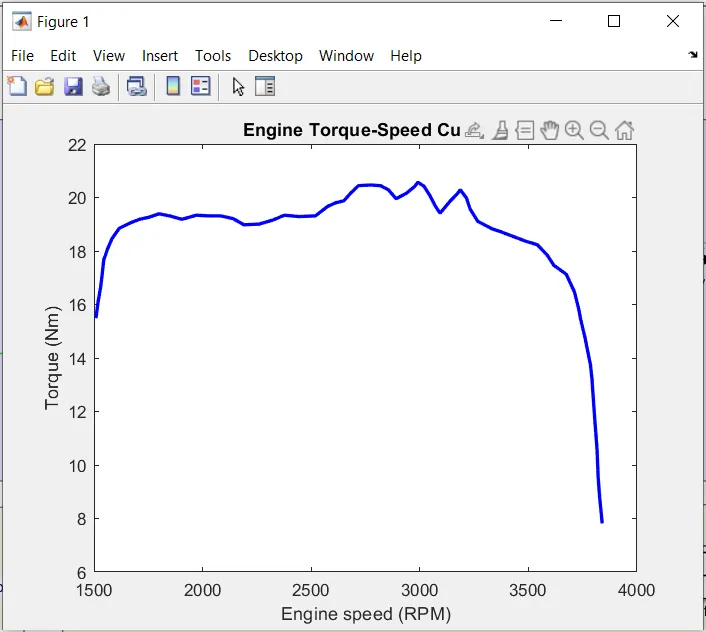
ENGINE TORQUE VS SPEED CURVE:
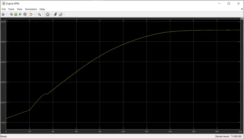
ENGINE RPM VS SPEED GRAPH:
LOOKUP TABLE:
CVT RATIO:
VELOCITY,THROTTLE,BREAK INPUT:
CVT GEAR RATIO:
STUDY 4) CVT MODEL DASHBOARD MAPPED
MODEL:
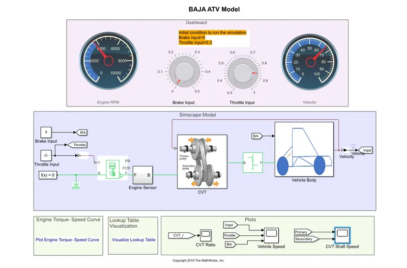
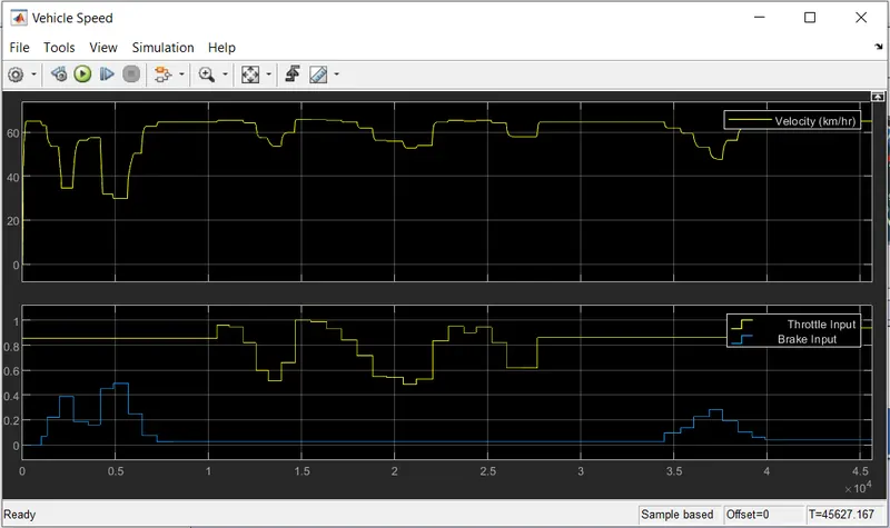
The fow process is same as study 3 but both the throttle input and brake input are given by the user.
OUTPUTS:
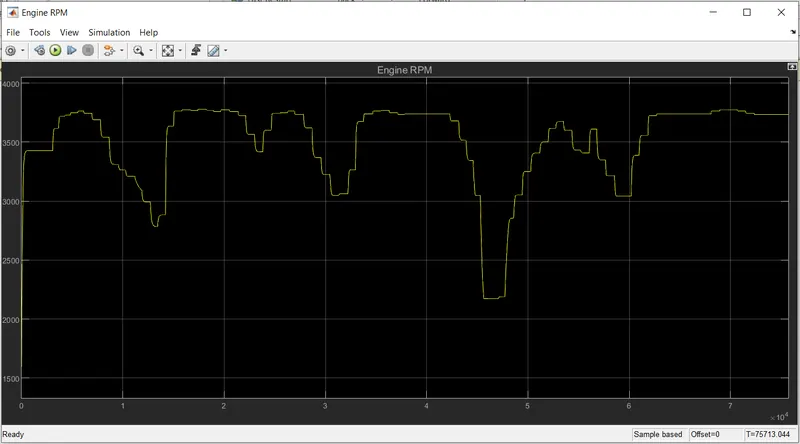
ENGINE RPM:
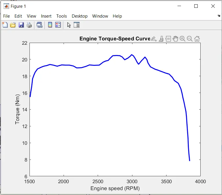
ENGINE TORQUE VS SPEED CURVE :
LOOKUP TABLE:
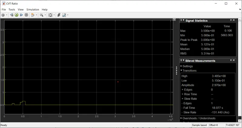
CVT RATIO:
VELOCITY,THROTTLE,BRAKE:
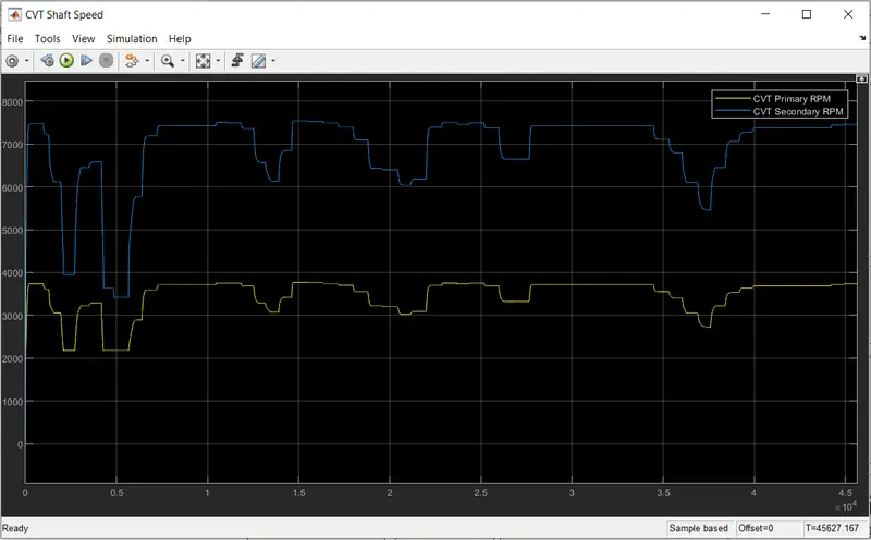
CVT SHAFT SPEED:
Thus we have succesfully 4 different models of BAJA ATV with CVT and recorded the outputs with respect to variation in input throttle and brake.