Simulink model of a Solenoid Doorbell and a Thermistor Temperature sensor to turn ON/OFF a fan.
Aim:
- To make a Simulink model of a doorbell using solenoid.
- To use a thermistor to sense the temperature of a heater and turn ON/OFF a fan.
Simulink model of a Doorbell:
Objective:
- To make an electric doorbell using solenoid.
- To create a situation where the doorbell is closed for 2 seconds and then released for next 2 seconds.
- To observe the physical movement of the plunger of the electromagnet/solenoid.
Simulink model of an electric doorbell:
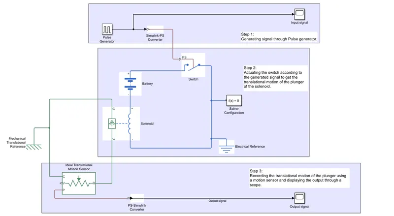
Results:
- Input signal by the pulse generator.
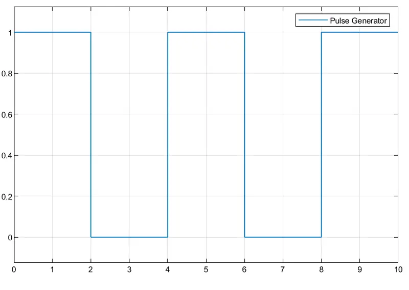
When the signal value is ‘1’ the switch is ‘ON’ and when the signal value is ‘0’ the signal is ‘OFF’. From the graph, we can see that the switch is ‘ON’ for 2 seconds and ‘OFF’ for next 2 seconds.
- Output signal from motion sensor.
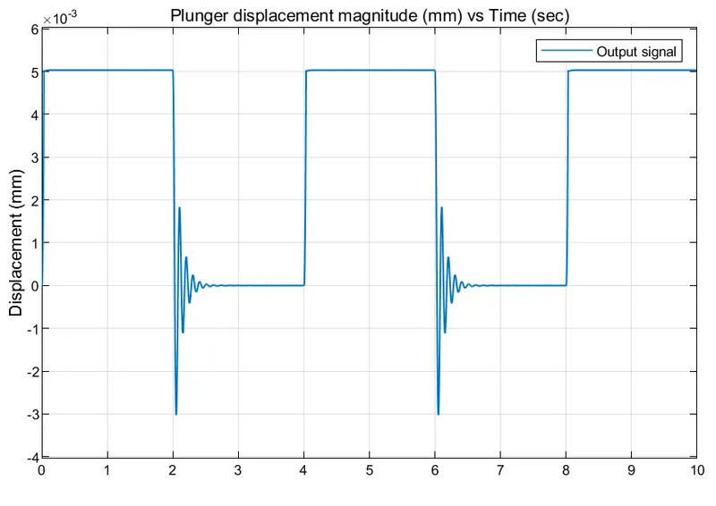
Plunger attain its maximum displacement of ‘5mm’ when the switch is ‘ON’. When the plunger is pulled to its full length due to electromagnetic force of the solenoid, it hits the metal bell cover, generating a ringing sound. At ‘0mm’ the switch is ‘OFF’. We can also see the oscillation of the plunger (2-3 sec & 6-7 sec) due to spring when the switch is turned off. The oscillation damps out quickly within 1 second.
Thermistor Temperature Sensor:
Objective:
- To use a Thermistor to sense temperature of a heater and turn ON/OFF a fan.
- Input Temperature signal, 20 deg C from 0 to 10 seconds, 27 deg C from 10 to 30 seconds and 23 deg C from 30 to 50 seconds.
- Fan is ON if the Temperature is above 25 deg C, otherwise OFF.
Simulink model of a Thermistor Temperature Sensor:
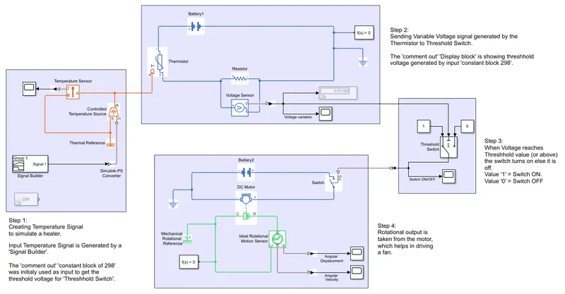
A thermistor is a cyramic or polymer material with 2 wires connected to it. Thermistor is a type transducer which changes its resistance with change in temperature.
With some thermistors, resistance increases with temperature incease, those are called Posetive temperature coefficient (PTC) thermistors. With other thermistors, the resistance decreases with increase in temperatre those are called negative temperature coefficient (NTC) thermistors.
For this model we are using NTC thermistor.
Results:
- Input Temperature (in kelvin) to the Thermistor.
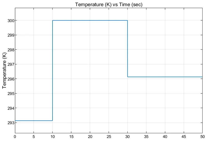
The plot shows temperature signal generated by the signal builder. This temperature signal is the input to the thermistor.
- Voltage Variation by the Thermistor with respect to the input temperature.
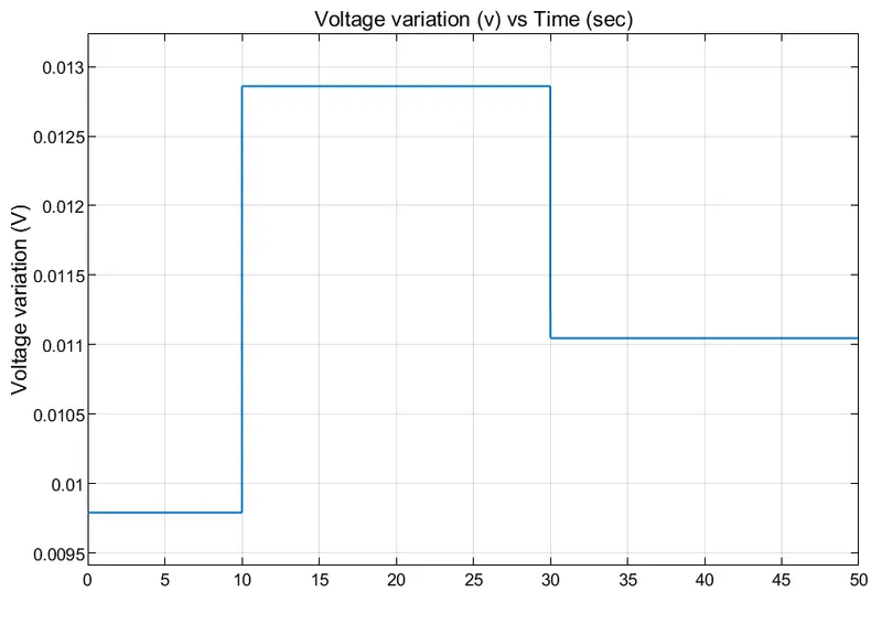
The plot shows, variation in voltage with time. This variation in voltage is generated by the thermistor with change in temperature.
- Output by the Threshold switch.
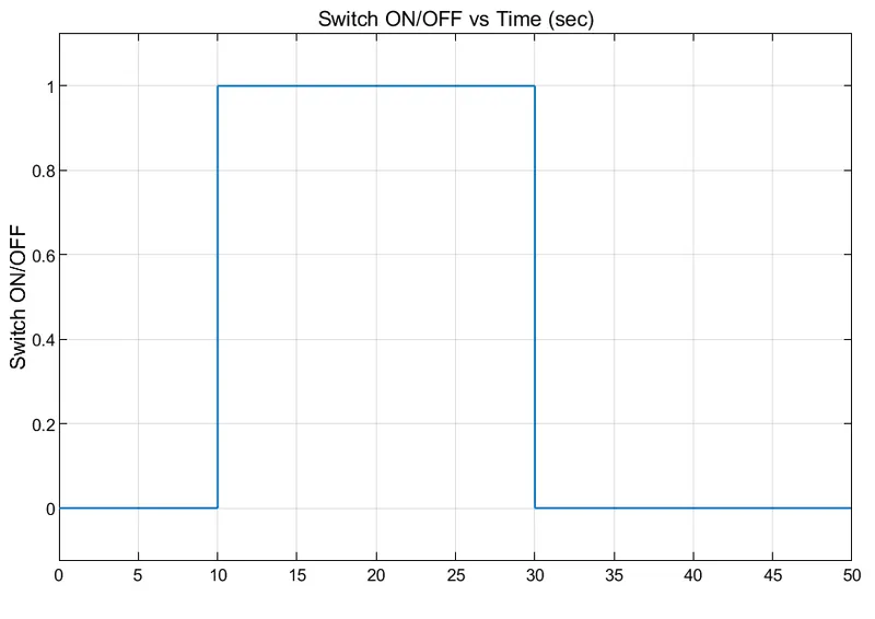
Switch is OFF from 0-10 seconds and 30-50 seconds. Switch is ON for 10-30 seconds when the threshhold voltage is reached.
- Output from ‘Rotational motion sensor’.
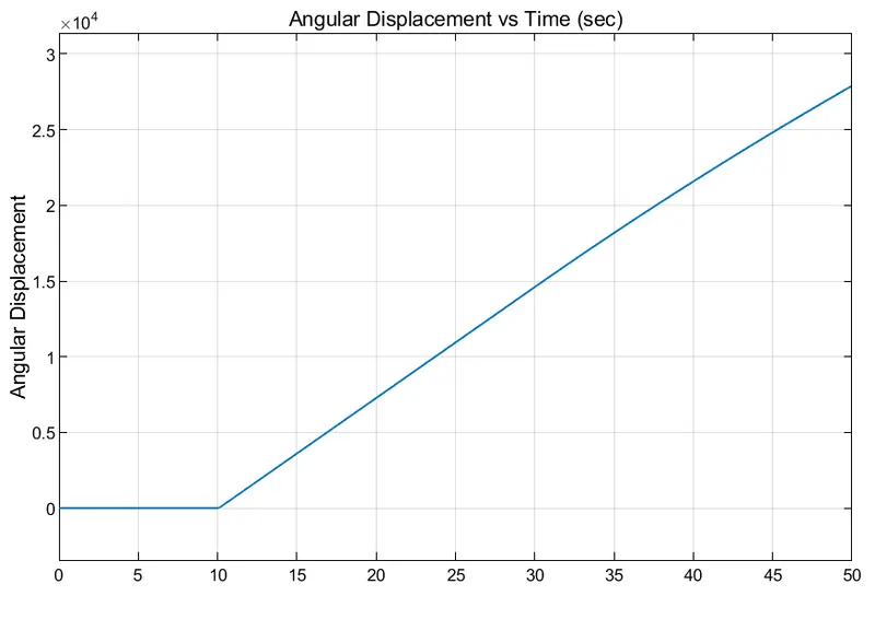
The plot shows, Angular displacement is zero when motor is OFF for 0-10 seconds. The Angular Displacement increases as the motor starts running after 10 seconds.
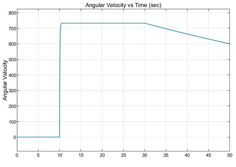
For 0-10 seconds motor is OFF. For 10-30 seconds constant angular velocity is maintained as the voltage crosses threshold voltage due to increase in temperature beyond 25 deg C. For 30-50 seconds, as the temperature starts to decrese, the voltage started decreasing, resulting in lower angular velocity of the motor.