Week -2
MODEL-1
AIM:
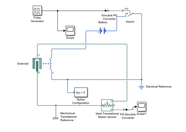
To Make a Simulink model of Doorbell using solenoid block.
OBSERVATION:
- Pulse generator - The Pulse Generator block generates square wave pulses at regular intervals. The block waveform parameters, Amplitude, Pulse Width, Period, and Phase delay, determine the shape of the output waveform. The following diagram shows how each parameter affects the waveform.
- Simulink-PS Converter - The block converts the input Simulink signal into a physical signal. Use this block to connect Simulink sources or other Simulink blocks to the inputs of a Physical Network diagram.
- PS-Simulink Converter - The block converts a physical signal into a Simulink output signal. Use this block to connect outputs of a Physical Network diagram to Simulink scopes or other Simulink blocks.
- PS Switch - The block compares the value of the physical signal presented at the second (middle) input port to the threshold value: If the control input value is greater than or equal to the threshold, the output is connected to the first input.
- Battery - The block implements a generic dynamic model that represents most popular types of rechargeable batteries.
- Scope - The block display time domain signals.
- Solenoid - The block is connected with switch and battery and we will get a complete electrical circuit.
- Solver Configuration - The block specifies the solver parameters that your model needs before you can begin simulation.
- Mechanical Translational Reference - The block represents a reference point, or frame, for all mechanical translational ports.
- Electrical Reference - The block represents an electrical ground.
- Ideal Translational Motion Sensor - The block represents a device that converts an across variable measured between two mechanical translational nodes into a control signal proportional to velocity or position.
PROCEDURE:
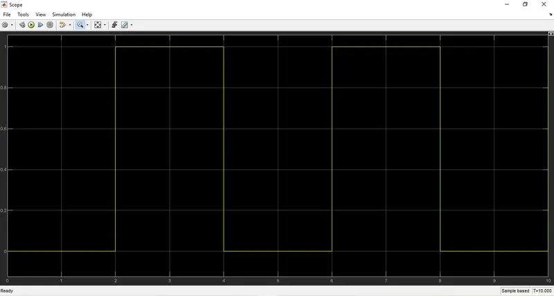
- A pulse generator is given as input with following conditions that the bell is engaged for 2 seconds and released. And amplitude of 1 for the pulse width of 50% for4 secs, phase delay of 2 secs.
- The signal from the generator can be converted by the simulink-PS converter and is given as the input to the PS switch.
- The PS switch is connected to the solenoid and battery where the voltage of battery is rated same as solenoid.
- The position of Solenoid plunger is measured using as ideal translational motion sensor connected across the circuit.
- The circuit also connected across mechanical and electrical references.
- The output of motion sensor is converted using PS-sinulink converter and is given to the scope to display the results.
- The behaviour of plunger is visualized in scope block.
SIMULNK BLOCK DIAGRAM:
PLOT:
INPUT SIGNAL
RESULT:
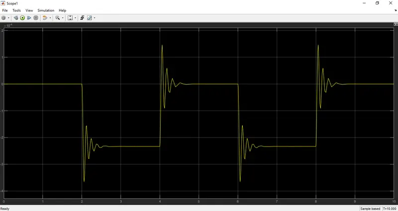
The simulation was ran for 10 seconds and the resultare obtained as shown in above graph. Thus the obseravtion is made at each 2 seconds interval the bell is ringing.
MODEL-2
AIM:
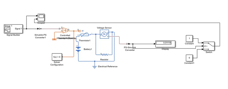
To Make a thermistor to sense the temperature of a heater & turn on or turn off the fan.
OBSERVATION:
- Signal generator - The block can produce one of four different waveforms. A negative Amplitude parameter value causes a 180-degree phase shift.
- Simulink-PS Converter - The block converts the input Simulink signal into a physical signal. Use this block to connect Simulink sources or other Simulink blocks to the inputs of a Physical Network diagram.
- PS-Simulink Converter - The block converts a physical signal into a Simulink output signal. Use this block to connect outputs of a Physical Network diagram to Simulink scopes or other Simulink blocks.
- Switch - The block passes through the first input or the third input signal based on the value of the second input. The first and third inputs are data input. The second input is a control input. Specify the condition under which the block passes the first input by using the Criteria for passing first input and Threshold parameters.
- Battery - The block implements a generic dynamic model that represents most popular types of rechargeable batteries.
- Scope - The block display time domain signals.
- Display - The block shows the value of the input data. We can specify the frequency of the display.
- Solver Configuration - The block specifies the solver parameters that your model needs before you can begin simulation.
- Constant - The block generates a real or complex constant value signal.
- Thermal Reference - The block represents a reference point, or frame, for all thermal translational ports.
- Electrical Reference - The block represents an electrical ground.
- Voltage Sensor - The block represents an ideal voltage sensor, that is, a device that converts voltage measured between two points of an electrical circuit into a physical signal proportional to the voltage.
- Controlled Temperature Source - The block represents an ideal source of thermal energy that is powerful enough to maintain specified temperature difference across the source regardless of the heat flow consumed by the system.
- Thermistor - The block represents an NTC thermistor using the B-parameter equation. The resistance at temperature 'T' is
R=R0eB(1/T−1/T0).
- Resistor - The block models a linear resistor, described with the following equation:
V=I*R.
PROCEDURE:
- A signal generator is given as input with following conditions that the temperature for 0-10 secs is 293 K, 10-30 is 300 K and 30-50 secs is 296 K.
- The signal from the generator can be converted by the simulink-PS converter and is given as the input to the thermistor by using controlled temperature source.
- The thermistor is connected to a linear resistor and the the voltage across the resistor is receiced by a voltage sensor for measuring the value.
- Then calculate the voltage across the circuit using display block and aslo the output can be converted by using PS- simulink converter.
- For the fan to operate it above 25 °C, use the switch block to develop a condition using constant blocks.
- Switch block has thershold value same as shown in display block.
- If the temperature across circuit reaches above 25 °C, the voltage across the circuit is greater than or equal to the display block value. And the fan is set to ON.
- If the temperature across circuit reaches below 25 °C, the voltage across the circuit is less than or equal to the display block value. And the fan is set to OFF.
SIMULNK BLOCK DIAGRAM:
PLOT:
INPUT SIGNAL AND OUTPUT SIGNAL
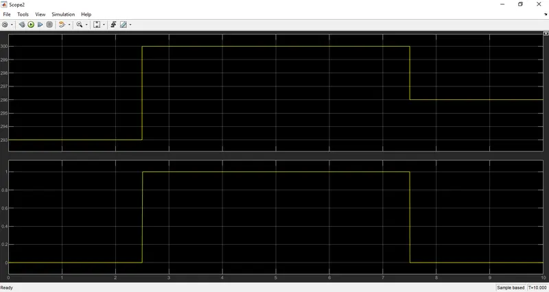
- For time 0-10 secs fan is OFF because the temperature is 20 °C (293 K) which is below the thershold 25 °C (298 K).
- After 10 secs temperature reaches 27 °C (300 K), then the switch will be in ON condition as the temperature exceeds the thershold value 25 °C (298 K).
- After 30 secs the fan will turn OFF as the temperature comes down to 23 °C (296 K) which is below the thershold value 25 °C (298 K).