Simulink model for Doorbell and NTC Thermistor for heater sensing.
Aim:
To make a Simulink model for Doorbell and NTC Thermistor for heater sensing.
Objective:
1. Make a Simulink model of Doorbell using a solenoid block with the following details:
In the above arrangement, when the switch is closed the electromagnet receives electrical power from the battery and pulls the metal arm to hit the bell producing sound.
Create a situation where the switch is closed for 2 seconds and then released. Observe the physical movement of the plunger.
Assume remaining parameters.
2. Use a thermistor to sense the temperature of a heater & turn on or turn off the fan as per the below conditions:
Temperature source: 20 °C from 0 to 10 seconds, 27 °C from 10 to 30 seconds, 23 °C from 30 to 50 seconds
Fan conditions: ON if the temperature above 25 °C, OFF otherwise
Theory:
Doorbell:
- A Doorbell is a signaling device typically placed near a door to a building's entrance. When a visitor presses a button the bell rings inside the building, alerting the occupant to the presence of the visitor.
- Although the first doorbells were mechanical, activated by pulling a cord connected to a bell, modern doorbells are electric, operated by a pushbutton switch. Modern doorbells often incorporate intercoms and miniature video cameras to increase security.
Solenoid:
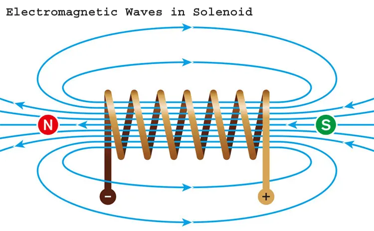
A solenoid is a type of electromagnet, the purpose of which is to generate a controlled magnetic field through a coil wound into a tightly packed helix. The coil can be arranged to produce a uniform magnetic field in a volume of space when an electric current is passed through it. The term solenoid was coined in 1823 by André-Marie Ampère to designate a helical coil.
- The coil is made of many turns of tightly wound copper wire. When an electrical current flows through this wire, a strong magnetic field/flux is created.
- The housing, usually made of iron or steel, surrounds the coil concentrating the magnetic field generated by the coil.
- The plunger is attracted to the stop through the concentration of the magnetic field providing the mechanical force to do work.
Components used in the circuit :
- Solenoid
- Switches
- Electrical power supply (DC)
- A bell with pivoted lever
- Some motion sensors for solenoid
Thermistor:
A thermistor is a type of resistor whose resistance is strongly dependent on temperature, more so than in standard resistors.
There are mainly two types of thermistors, namely the Negative Temperature Coefficient (NTC) and the Positive Temperature Coefficient (PTC).
Thermistor’s relation with temperature also depends on the material in which it is made.
A negative temperature coefficient (NTC) thermistor will decrease its resistance value when temperature increases
A positive temperature coefficient (PTC) will increase its resistance when temperature increases.
Procedure:
1. Doorbell model:
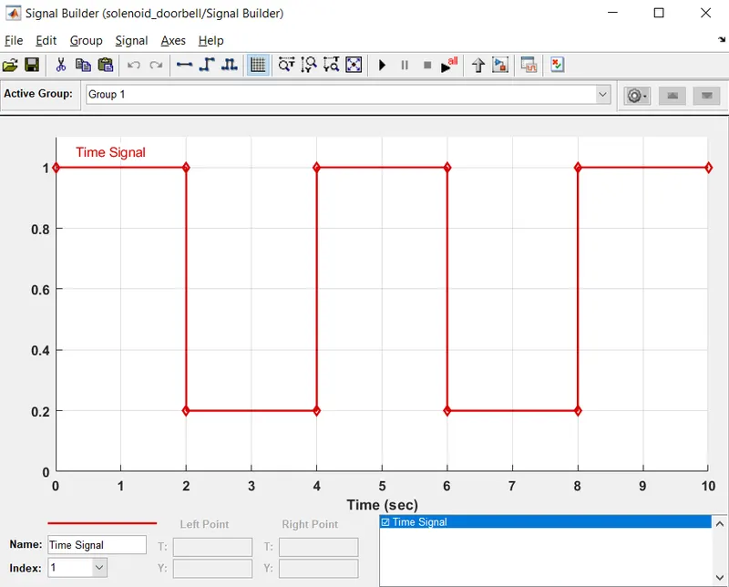
The Doorbell signal needs to be in a way that it should ring for 2 secs and then it stopped.
A signal builder is used to create a graph for a 2-sec rise and then a 2-second drop.
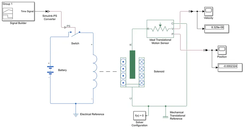
- We need to attach the signal builder to Simulink to the PS converter because the source is a Simulink input and so the switch is physical and then to a switch that is attached to a battery.
- The battery is used to have an electrical reference that works as earthing.
- The output of the switch is connected to the solenoid and the other end of the solenoid is connected to the battery creating a proper input electrical circuit.
- The solenoid has a coil and a rod and the rod is displaced to change current to the coil.
- The R and C on the solenoid block represent the plunger and the reference point respectively.
- To measure the displacement for the solenoid plunger, an ideal translational motion sensor is connected to the solenoid (R to R and C to C ports of the sensors) and V will be our velocity output.
- Now, attach the circuit with Mechanical Translational Reference as a reference point for the movement of the plunger and measure the actual displacement.
- The solver configuration block is attached to the circuit to provide the guide to the ode solver to solve the circuit.
- Run the code and click on the scope attached to check the graphs.
2. Thermistor model:
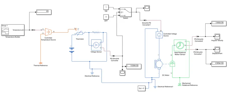
- The circuits for the NTC thermistor require a heating source, a thermistor, a signal builder, a resistor, a DC motor, and some switches and voltage regulators.
- The Circuit starts with a signal builder in which a signal is created with the temperatures as given above ( 0 to 10 secs – 20 °C, 10 to 30 secs - 27 °C, 30 to 50 secs - 23 °C)
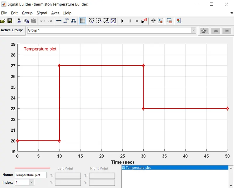
So the fan will turn on and turn off with the above conditions only when the temperature rises above 25 Degrees Celsius.
- The circuit starts with a Controlled Temperature Sensor (CTS) which requires a heater input source and it is provided through a signal builder block with certain temperature values at a certain time (secs).
- The signal builder input is connected to the Simulink-PS converter to change the form of input and then it goes to port S of the Controlled Temperature Sensor and another port A is connected to the Thermal reference block.
- Thermistor block contains Negative, Positive, and T port where the T port is connected with the B port of CTS. Resistor and Battery are connected to the thermistor block Negative (-) to Negative(-) and Positive (+) to Positive (+) terminals.
- The Voltage sensor is placed between the resistors (Make sure that it is parallel to the resistor).
- A solver configuration block and Electrical Reference are used to solve the ODE equations and to give earthing respectively.
- The physical port V from the Voltage sensor is connected to a PS to Simulink Converter which is connected to a Switch.
- The Switch is connected to constants 1 and 0 which represent the ON and OFF of a switch, threshold value is given in the switch block is 5.515e-22.
- The output of the switch is connected to the Controlled Voltage Source negative end.
- The Positive end of the Controlled Voltage Source is connected to a DC source and negative to a negative.
Results:
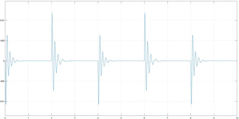
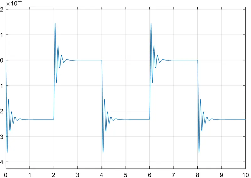
The Doorbell is created in the condition where it will ring just for 2 secs, then it will stop and repeat it.
Velocity vs Time plot:
Displacement vs Time plot:
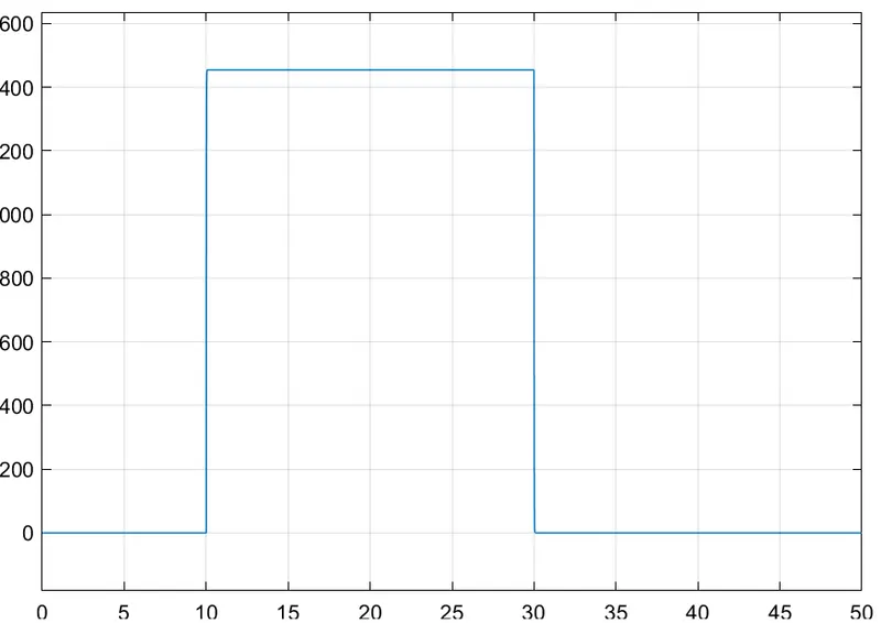
Thermistor circuit shows that its given conditions,
Angular velocity graph for fan with respect to time:
Angular displacement graph for fan with respect to time:
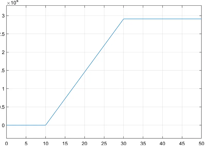
Conclusion :
The Simulink model for the doorbell and thermistor was created successfully.